HAL Id: cea-02509146
https://hal-cea.archives-ouvertes.fr/cea-02509146
Submitted on 16 Mar 2020
HAL is a multi-disciplinary open access
archive for the deposit and dissemination of
sci-entific research documents, whether they are
pub-lished or not. The documents may come from
teaching and research institutions in France or
L’archive ouverte pluridisciplinaire HAL, est
destinée au dépôt et à la diffusion de documents
scientifiques de niveau recherche, publiés ou non,
émanant des établissements d’enseignement et de
recherche français ou étrangers, des laboratoires
F. Baqué, F. Jadot, R. Marlier, J.-F. Saillant, V. Delalande
To cite this version:
F. Baqué, F. Jadot, R. Marlier, J.-F. Saillant, V. Delalande. In service inspection and repair of the
sodium cooled ASTRID reactor prototype. ICAPP 2015 - International Congress on Advances in
Nuclear Power Plants, May 2011, Nice, France. �cea-02509146�
IN SERVICE INSPECTION AND REPAIR OF THE SODIUM COOLED ASTRID
REACTOR PROTOTYPE
F. Baqué1, F. Jadot2, R. Marlier3, J.Fr. Saillant4, V. Delalande5
1CEA Cadarache, DEN/DTN/STCP/LIET, Bât. 202, 13108 St Paul lez Durance CEDEX, France Tel. 33 4 42 25 38 30 francois.baque@cea.fr
2
CEA Cadarache, DEN/DER/CPA, Bât. 155, 13108 St Paul lez Durance CEDEX, France Tel. 33 4 42 25 75 71 francoise.jadot@cea.fr
3AREVA NP, 10 rue Juliette Récamier 69456 Lyon CEDEX 06, France Tel. 33 4 72 74 81 07 regis.marlier@areva.com
4AREVA NDE SOLUTIONS, 4 rue Thomas Dumorey71100 Chalon-sur-Saône, France Tel. 33 1 34 96 20 35 jean-francois.saillant@areva.com
5EDF R&D, 6, quai Watier, 78401 Chatou, France Tel. 33 1 30 87 75 39vincent.delalande@edf.fr
Abstract – Within the framework of large R&D studies performed for the future sodium-cooled
reactor prototype called ASTRID, in-service inspection and repair (ISI&R) has been identified as a major issue to be taken into account in order to improve the reactor’s safety, to consolidate its availability and to protect its related investment.
Following on from the pre-conceptual design phase (2008-2012), the conceptual phase (2013-2015) is now focusing on improving the ISI&R tool for structures immersed in sodium at about 200°C in the ASTRID reactor. This work is based on a set of consolidated specifications and a qualification process involving increasingly more realistic experiments and simulations performed with the CIVA code.
ISI&R items are being developed and qualified as part of a multi-year program which mainly deals with the reactor block structures, the primary components and circuit, and the power conversion system (PCS).
This program is ensuring the strong ties needed between the reactor designers and inspection specialists since the aim is to optimize inspectability and repairability. This has already induced specific rules for design in order to shorten and facilitate ISI&R operations. These new rules have been merged into the RCC-MRx rules.
Current R&D deals with the following ISI&R items:
• Under-sodium non-destructive examination (NDE) of welded joints on the ASTRID supporting core structure (so called strongback): sodium testing and simulation are being performed
• NDE of welded joints on the ASTRID strongback supporting skirt, from outside the primary sodium (through the main vessel wall): water testing and simulation are being performed
• Under-sodium NDE of welded joints on the ASTRID above-core structure: water testing and simulation are being performed
• Under-sodium telemetry and vision of immersed structures and components forming the ASTRID primary vessel: improved techniques of scanning are being studied
• Primary circuit cover-gas telemetry of structures and components forming the ASTRID primary vessel
• Methods for in-situ repair: a laser technique has been selected
• Associated in-sodium robotics: a sodium-proof material and technology is being developed and tested
This paper provides the main testing and simulation results for telemetry, vision and NDE applications.
R&D for inspection and repair of SFRs faces challenging requirements and is progressing towards available technological solutions, associated with demonstrated performance levels: the basic inspection techniques are expected to reach level 6 of ‘technological readiness’ by the end of conceptual phase.
The ‘integrated readiness level’ is also discussed in this paper with respect to access within the reactor block, fluids, positioning and maintenance aspects.
I. INTRODUCTION
Within the framework of the future sodium-cooled fast reactor prototype called ASTRID, France has launched a large R&D program1 on in-service inspection and repair (ISI&R) which has been identified as a difficult task to perform2 (as sodium coolant is opaque, hot and highly chemically reactive) on the basis of experience feedback (French Phenix and Superphenix SFRs, as well as also foreign power plants). ISI&R is thus considered to be a major issue to be taken into account in order to improve the reactor’s safety (as inspection gives information on the actual reactor structure health), to consolidate its availability and to protect its associated investment.
Since 2009, R&D studies for ISI&R are parted into four levels. These levels are related to the specific rules for design applicable to SFRs3 (Fig. 1.).
A number of general options were chosen at the end of the ASTRID pre-conceptual design phase (2011-2012). The conceptual phase (2013-2015) is now focusing on improving the ISI&R tool4 for the ASTRID reactor block structures immersed in sodium at about 200°C. This is being done on the basis of consolidated specifications and a pre-qualification process involving increasingly more realistic experiments using acoustic techniques5 and simulations performed with the patented CIVA code.
ISI&R items (inspection: ultrasonic sensors, telemetry, vision and volumetric control, repair, associated robotics) are being developed and qualified within the scope of a multi-year program6 which mainly deals with the reactor block systems, structures and components, and the power conversion system. One has to note that repair aspect is considered to be less important than inspection one.
This program is ensuring the strong ties needed between the reactor designers and inspection specialists since the aim is to optimize inspectability (and repairability): this has already induced specific rules for design in order to shorten and facilitate the ISI&R operations, these new rules have been merged into the RCC-MRx rules (2012 edition).
Thus, ISI&R will participate to ASTRID prototype safety, as it will be able to face the standards associated to high level requirements for nuclear plants.
In the present conceptual design phase (2013-2015), R&D activities deal with general ISI&R objectives (for example: being able to perform NDE under sodium) which will be declined for each case during basic design phase, depending on what will be exactly required.
II. R&D FOR ISI&R OF ASTRID
The design of the ASTRID reactor prototype aims at minimizing the inspection needs (e.g. the fewer welding joints, the better) and to facilitate access to areas which should be inspected due to their safety function. The in-service inspection of systems, structures and components will depend on their contribution to the reactor’s defense and mitigation lines.
The inspection graduation applied to each system, structure and component is based on a set of parameters, among which are mainly the consequences of the structure failure on the reactor safety and/or defense and mitigation lines ; but also the structure service and hypothetical loading (design margins), its functions (containment, mechanical support…), its exploitation feedback…
The following sections deal with R&D on the improvement and qualification of inspection techniques: this is based on simulation and testing, first through feasibility assessments and then on the basis of increasingly more realistic tests for technological bricks and systems, i.e. the ‘technological readiness level’ and ‘integrated readiness level’ methodology.
R&D on repair focuses on a single laser technique for all applications while robotics is studied through architecture concepts, robot design, technological bricks and under-sodium leaktightness.
II.A. Under sodium ultrasonic sensors for telemetry and NDE
Development of in sodium ultrasonic sensors forms the basis of most of inspection techniques. It is why both piezoelectric (TUSHT from CEA and TUCSS from AREVA NDE SOLUTIONS) and electromagnetic acoustic (EMAT from CEA) technologies are being investigated to provide solutions that are adapted to the ASTRID inspection needs7.
Experimental tests performed in liquid sodium have already demonstrated the good performance of custom mono-element EMAT probes8. Telemetry measurements were also performed with good accuracy. The integrity of the immersed probes was assessed after testing and cleaning. It has thus been possible to validate the design of the probe casing based on a stainless steel container.
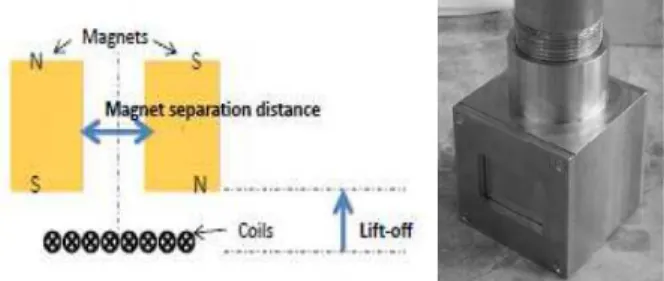
Developments have been continued to increase the performance and the capacity of the probe: an 8-elements EMAT probe has been designed and developed by Innerspec Technologies in accordance with the CEA specifications for under-sodium imaging (Fig. 2).
Fig. 2. Principle and photo of in sodium 8-phased array EMAT probe.
As can be seen on Fig. 3, under-sodium tests have shown the good performance of the probe for telemetry measurements with normal incidence. Deflection tests proved to be difficult due to the size of the focal spot compared with that of the targets. New developments are ongoing at the CEA to enhance the performance of this EMAT probe.
Fig. 3. A-SCAN of the EMAT echoes (in sodium at 110°C and 180°C).
The high-temperature ultrasonic transducer (TUSHT) developed by the CEA is a lithium-niobate-based probe: LiNbO3 piezoelectric crystal, enriched with 7LiNbO3 for
severe neutron irradiation conditions. The casing is made of AISI 304L stainless steel as shown on Fig. 3. and an efficient acoustic bonding between the casing and the crystal is provided via a hard-soldering technique. This provides stable high-frequency transmission (up to 5 MHz at least) in the temperature range applicable during both inspection (reactor shutdown state) and continuous surveillance and monitoring (reactor full power state) of SFRs.
Fig. 4. Photo of the TUSHT (4540 standard model).
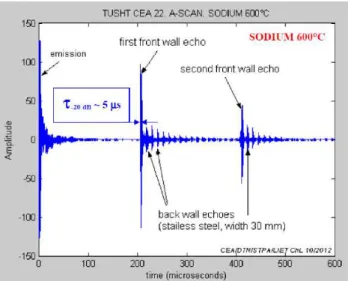
Fig. 5 shows the arrangement of the six TUSHT samples which were tested in sodium in a pulse-echo mode,
shooting on a target located at 230 mm. The target was a stainless steel plate with a thickness of 30 mm.
Fig. 5. TUSHT and target setting for sodium test.
As illustrated in the Fig. 6, ringing echoes are visible, in particular those resulting from internal reflections inside the target. The front-wall and back-wall echoes of the target are detectable, with the echo duration being 5 microseconds (width at -20dB).
Fig. 6. TUSHT acoustic signal during sodium test at 600°C.
The adaptation of the TUSHT technology can also be considered to develop array transducers. The next in-sodium experiments will consist in testing focused transducers (with a curved front face) to verify that they can achieve the expected standard focusing features (as they do in water conditions). The acoustic wetting of transducers machined with mirror-like polished front faces will also be tested.
AREVA is also developing transducers for specific applications regarding volumetric NDE under liquid sodium at 200°C. The objective of the development is to show that it is possible to detect a flaw inside a stainless steel structure immersed under liquid sodium9.
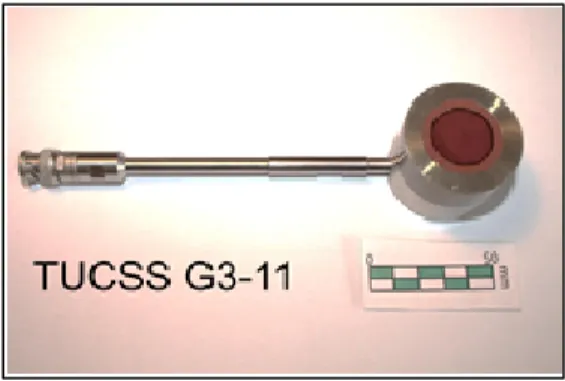
The developed transducers are based on piezoelectric crystal technology. A picture of a TUCSS transducer is shown on Figure 7. Its resonant frequency is 2 MHz and the emissive surface is a Ø20 mm diameter disc. Acoustic transmission can be obtained by using either a polished metallic front face or a polymer front face.
Fig 7. Photograph of a TUCSS transducer.
This transducer was immersed in a pot containing liquid sodium at 180°C facing a 316L stainless steel target, which included a 20 x 10 mm notch on its back side (see Figure 8-a). Multiple acquisitions were made as the transducer was immersed deeper and deeper in the sodium pot. The aggregation of these acquisitions allowed to produce the B-Scan showed in Figure 8-b. The large red zone on the left indicates the echo from the target’s front face and the light blue areas represent the echoes from the backwall (echo distance = 30mm) and from the notch (echo distance = 20mm) between the altitudes -10 mm and -25 mm.
This experiment shows that a change in shape at the rear side of a metallic structure immersed in sodium can be detected. This change in shape could for instance be a flaw.
Fig 8. B-scan of the interior a 30mm thick stainless steel target comprising a 20x10mm notch on its backside – a) sketch of the
experiment – b) B-scan
More complex testing devices are being designed in order to qualify such TUCSS transducers (see Figure 9). This device will allow to produce longitudinal waves and shear waves at a certain angle in a 316L block so that the capabilities of TUCSS transducers can be evaluated for performing different basic NDT inspections steps (L0°, L60°, T45° …).
B-Scan at 180°C a) b) TUCSS Ø20mm Stainless steel target S c a n 10 30 50 20
Fig 9. CAD representation of TUCSS testing device (DEFO)
Thus, this large work leads to efficient acoustic transducer availability which will participate to the priority inspection of ASTRID in sodium structures and components.
II.B. Under sodium NDE of welded joints within the ASTRID Supporting Core Structure (so called strongback)
Much is being done to improve and to propose the most suitable ISI&R strategy for the main ASTRID structures and equipment. The ISI&R strategy consists in proposing the appropriate mix of continuous monitoring, periodic examinations and extra access/ repair abilities for each given structure. Various aspects have to be studied and taken into account to reach this objective.
These aspects are: i) design of the equipment, ii) associated damage modes, iii) behavior of the equipment when damaged, iv) probability of failures, v) capabilities of the surveillance/examination devices (existing or to be developed) and, vi) economic criteria (cost of the devices, impact on the plant’s availability).
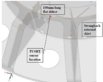
First of all, the supporting core structure (see Fig.10) is undergoing considerable analysis, as it is considered very important: a number of hypothetical inspection cases are being considered and simulated with the patented CIVA code which has been upgraded to meet SFR needs10.
As an example of CIVA simulation capacities compared with ASTRID extended accessibility issues, Fig. 10 shows
the hypothetical inspection of the welded joint between outlet skirt and upper plate. The arrow indicates the positions where the ultrasonic TUSHT sensor could be (assuming a simple rigid pole through the existing specific ISI&R access in the roof slab of the main vessel) and of an example targeted welded area where an hypothetical 100mm-long flat defect is located.
Fig. 10. CIVA code simulation of strongback inspection: example of NDE conditions.
The effect of the relative position (internal/ external) and depth (5/ 10/ 20 mm) of such a defect is studied. Fig. 11 shows the simulated echo amplitude calculated by the CIVA code: detecting such defects should be possible since the signal-to-noise ratio is high enough.
Fig. 11. CIVA code simulation of strongback inspection: example of NDE results.
In the frame of NDE studies, this demonstrates CIVA abilities to be a useful tool for extended accessibility verifications in ASTRID configurations.
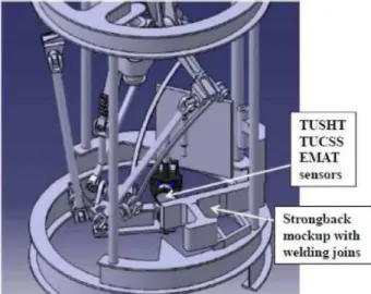
In 2015, sodium testing will be performed on a specific device where ultrasonic transducers (EMAT, TUSHT and TUCSS) will operate at 200°C in static sodium (see Fig. 12). Different types of strongback welded joints will be reproduced and their close-range inspection tested.
Fig. 12. Specific positioning device for US sensors, and strongback mockup for 2015 sodium close-range NDE tests.
II.C. NDE of welded joints within the ASTRID strongback support skirt, from outside primary sodium
(through main vessel wall)
Another important structure to be controlled is the strongback support skirt (see Fig. 16 where “inspection branch” corresponds to it). Three techniques based on inspection from outside the primary sodium are being investigated: i) Lamb waves which could propagate in sodium from one structure to another, ii) guides waves within structures welded to the main vessel, and iii) conventional volumetric waves.
Lamb wave propagation in multilayers can be considered as they can propagate with low attenuation. A simplified mockup of typical SFR vessels and shells has been manufactured with parallel steel plates immersed in water (20 and 30 mm thick).
Austenitic stainless steel plates are immersed in water and separated by 150 mm of water: Lamb waves are produced as a function of the frequency and the angle of incidence of the pressure waves produced by sensors in water.
Fig. 13. Modulus of the transmission coefficients through a set of two plates, along frequency and incidence.
The re-emission of such waves, from one plate to another, has been demonstrated. The behavior of waves can be predicted using the transfer matrix method together with the general equations for the dispersion curves, the normal displacements and the tangential displacements in the plate: acoustic modes can be determined as shown on Fig. 13.
Fig. 14. Experimental setup (left: 3D, right: 2D top view).
The acoustic emitter E was tilted to generate the expected Lamb mode in the first plate, while the receiver R (needle hydrophone) was positioned close to the edge of the plate. Thanks to its Y displacement, the emitted pressure waves could be recorded along the edge of both plates (see Fig. 14).
As shown on Fig. 15, A0 and S0 modes were observed in the first plate and identified by the measurements of celerity and displacements at the interface with water. The angles of radiated pressure waves were measured to ensure that the incident waves on the second plate could generate Lamb waves. Then the propagating modes were also observed and identified in the ‘hidden’ plate.
Fig. 15. Pressure amplitudes measured along the edge of the second plate. Left: antisymmetric mode. Right: symmetric mode.
Experimental validations show good agreement with theory and highlight Lamb wave propagation in the hidden plate. The A0 mode could be used for the non-destructive testing of the hidden plate.
Guided waves can also be used, as the strongback support skirt is welded to the main vessel: this configuration implies a continuous stainless steel guide, from outside the main vessel up to the strongback11.
Guided wave modeling has been developed with a hybrid finite-element modal method for arbitrary waveguides. The method couples high-order finite elements that allow the interaction of guided waves with arbitrary defects with a modal expansion that permits semi-analytical propagation along waveguide principal axes. Between the different modal decompositions, scattering matrix formalism is applied to easily chain complex geometries to each other with emission and scattering phenomena.
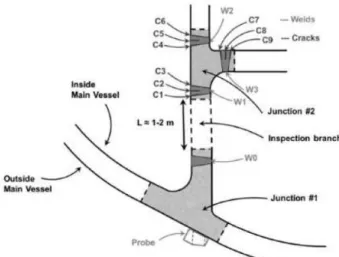
A case study featuring a branched steel structure representative of strongback supporting skirt welded on the main vessel was simulated to determine the effect of cracks on the pulse-echo inspected region. This is shown in Fig. 16.
Fig. 16. Case study for guided wave inspection (top) and inspection configurations used (bottom).
A parametric study was conducted for each emission configuration to determine the optimal location of the probe, its size and frequency of operation, depending on the modes generated in the control branch. After choosing the optimal set-up, pulse-echo ultrasonic guided wave simulation was carried out with cracks C1 to C9 present one at a time. These studies revealed the fact that modal contributions are strongly dependent on the emission configuration used. In the case of cracks C7, C8 and C9, which are located in a geometrically inaccessible region, a variation of 6 dB between the best and the worst inspection configuration can be observed.
Further work on this topic will include experimental validation of the simulation results relating to this type of complex branch-like structural inspection
Volumetric waves seem less likely to be successful, as the distance to the reactor vessel and the amplitude decrease in successive echoes from a surface perpendicular to the incident ray direction limits the detectability of internals.
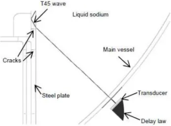
Nevertheless, simulation was performed to check the efficiency of different sensors for the upper part of the strongback supporting skirt inspection configuration: a non-destructive examination of two cracks inside the skirt was simulated, as illustrated on Fig. 17.
Fig. 17. Configuration of T45 inspection of strongback supporting skirt with two cracks, from behind the main vessel.
A 45° shear wave inspection (T45) was simulated with CIVA code, assuming a phased array probe positioned outside of the main vessel. The resulting B-scan has been projected onto the geometry of the reactor in Fig. 18.
Fig. 18. NDE simulation of T45 inspection of strongback supporting skirt with two cracks, from behind the main vessel.
In the case of this inspection, the crack echoes show not only the specular corner reflection of the T45 beam, but also the tip diffraction echoes that make it possible to size the cracks. A validation case with steel plate mockup immersed in water will be set up to estimate whether this inspection technique is also adapted in practice.
Another configuration is being studied for the inspection of vertical welded joins of the core supporting
skirt: using out-of-sodium sensors, ultrasonic volumetric waves are likely to cross the main vessel wall and then propagate across the skirt where they have to cross a horizontal welded join.
Fig. 19. Core supporting skirt mock ‘up, during water tests.
A first mock-up was designed and manufactured (see Fig. 19) to check the detection of artificial cracks in its 40mm-deep welded joins, with the mock-up immersed in water as shown on Fig. 20 (representing the surrounding sodium of the current ASTRID conditions) and using a single 128 phased-array 5 MHz sensor.
Fig. 20. Under water test configuration for vertical welded joint inspection with one 128 element sensor (plane wave case).
The NDE measurements corresponded to the time-of-flight diffraction (TOFD) on artificial slit edges: 64 elements of the phased-array sensor emitted plane waves or focused waves, thanks to the former CIVA code calculation of the corresponding time delay laws. The other 64 elements acted as receivers (see Fig. 20).
Fig. 21. NDE of core supporting skirt mockup (water test results at room temperature).
The NDE of this mock-up was performed first without and then with some artificial slits which were inserted in the welded joints or in their heat-affected zone (see Fig. 21).
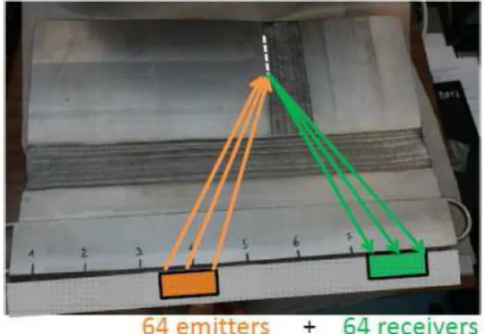
The echoes of the slits to be detected could not be found: there was no specific response associated with the slits. This is why these tests will be repeated with not one but two 64 element transducers, with each transducer being able to move along the length of the mock-up, so that incidence of acoustic beam on the slit to be detected will be larger (see Fig. 22).
Fig. 22. Under water test configuration for vertical welded joint inspection with two 64 element sensors (focused wave case).
Of course, CIVA code simulation will also be used to predict the echoes from the slit edges in order to use the best configurations for NDE.
II.D. Under sodium telemetry and vision of immersed structures and components within the ASTRID primary
vessel
Complementary acoustic techniques such as in sodium imaging are also considered, even if they are less important than NDE ones (see above). As sodium is opaque,
visualizing components and structures immersed in sodium could provide interesting information for some applications: accurate local vision for structure surface metrology, global vision of the primary circuit, detection of opened cracks, location and identification of loose parts, robotic navigation positioning, and identification of coding systems for fuel sub-assemblies.
The study has been divided into several parts:
o Acoustic behavior of such systems, using the CIVA code simulation
o Development of associated transducers (phased-array systems)
o Signal treatment for 2D and 3D image reconstruction (advanced signal processing techniques)
o Qualification by in-water and then in-sodium tests using dedicated targets for each application. This study is being carried out with the help of French and international partners.
In a preliminary phase, telemetry tests were performed in 2010 on a mock-up called MULTIREFLECTEUR in order to study ultrasonic diffractions and reflections in liquid sodium. It included a rotating TUSHT, a fixed target, rotating targets and thermocouples (see Fig. 23). In order to reach the metrological objective, all the components were initially calibrated in air at room temperature, which resulted in a global uncertainty of ± 0.02 mm (20µm) for their location and ± 0.02° for their angular position.
Fig. 23. MULTIREFLECTEUR mockup for telemetry sodium tests.
After under-water commissioning tests, the mock-up was dried and used in a 1m-diameter pot in isothermal 200°C static sodium conditions: the test parameters were the TUSHT frequency and 6 target positions. The global uncertainty on the ultrasonic distance measurement was checked and proved to be better than 100 µm. The test results helped qualify the CIVA code.
In late 2013, PhD work was launched at the CEA to find the best techniques for visualizing opened cracks and for optimizing the related acoustic systems, based on numerical simulation and combined with experimental qualification.
Surface-breaking cracks and deep cracks were sought in the weld area as welds are more subject to defect initiation.
Traditional methods enabled us to detect emerging cracks of sub-millimeter size with the sodium-compatible high-temperature transducer (water tests). The current PhD work relies on making use of prior knowledge of the environment by implementing differential imaging and time-reversal techniques. This approach makes it possible to detect change by comparison with a reference measurement and by focusing back to any change in the environment. It provides a means of analysis and understanding of the physical phenomena, thus making it possible to design more effective inspection strategies. The differences in the measured signals revealed that the acoustic field was scattered by a perturbation (a crack for instance), which may have occurred between periodical measurements.
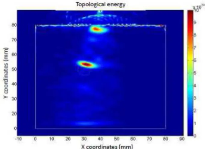
The imaging method relies on the adequate combination of two computed ultrasonic fields, one forward and one adjoint. The adjoint field, which carries the information about the defects, is analogous to a time-reversal operation. One of the advantages of this method is that the time-reversal operation is not done experimentally but numerically. Numerical simulations have been carried out to validate the practical relevance of this approach as shown on Fig. 24. The preliminary numerical results show good agreement between the predicted and the actual positions of the defect.
Fig. 24. Calculated topological energy for the case of a stainless steel block with an air cavity (adjoint field method).
The water tests were performed in much simplified conditions, with conventional sensors which were accurately moved with 5D systems12 (see Fig. 25).
Fig. 25. VISIO water facility (2 m long, 1 m large, 1 m heigh) devoted to ultrasonic visualization study.
With these test conditions, it was possible to detect artificial slits (simulating opened cracks) whose width is only 800 µm (ASME specification for visual inspection) and letters whose size is more than 6 mm as shown on Fig. 26).
Fig. 26. Acoustic imaging of a plate with slits. Left: time of flight. Right: amplitude (under water test at room temperature).
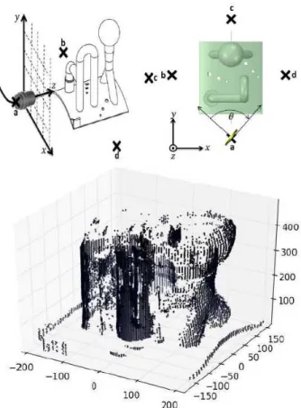
The main components of a 3D mock-up – a specially designed specimen that simulates various structure shapes found inside the ASTRID reactor block (pipe, elbow, reducer, plate and sphere) – have been identified through US scanning, but all its details are not always visible. For example, when the immersed objet is not flat, only the specular echoes are useful for imaging. Thus, it became apparent how important it was to choose the right strategy for sensor positioning and displacement along the targets to be imaged.
In addition to water testing, CIVA simulation was also carried out to obtain 3D images of the simulated specimen that were generated by XY raster and Z-theta approaches as shown on Fig. 27.
Fig. 27. XY raster and Z-theta approaches for CIVA code calculation of 3D mockup. Z-theta CIVA results.
The simulation studies indicate that both XY raster (illustrated on Fig. 28) and Z-theta scan can be used for deciphering the shapes.
Fig. 28. In water 3D mockup ultrasonic imaging with sensor displacement in a vertical plan (echoes amplitude).
After the water-tests, in sodium-tests must be performed to validate the water/sodium transposition. For this purpose, the same 3D scanning system which will be
used for strongback NDE sodium testing (see Fig. 12 above) will be used for future under-sodium imaging of objects in a CEA test vessel (in 2015). It can move some transducers (TUSHT, TUCSS and EMAT types) with four degrees of freedom in a 1.5 m3 sodium vessel.
In the meantime, the first raw imaging of 200°C sodium-immersed objects (bolt, hammer and pliers) was performed in 2013, as shown on Fig. 29.
Fig. 29. In sodium acoustic imaging at 200°C: first plier raw reconstruction. Left: time of flight. Right: amplitude.
II.E Methods for in-situ Repair
In the frame of ASTRID project, R&D effort for repair was lower than for inspection and mainly done during pre-conceptual and pre-conceptual design phases.
The laser process was assessed as a possible repair tool13 because it has the advantage of being suitable for the steps to be performed (1. removal of sodium traces, 2. machining or gouging, and 3. welding of the stainless steel structural material), without generating any stress on the tool. Conventional tools (brush or gas blower for sodium removal, milling machine for machining, and TIG for welding) are only considered as back-up solutions.
The laser technology covers a wide range of applications: heat treatment (in solid phase), welding (in liquid phase), cutting, engraving, machining, drilling, laser shock peening (LSP) and cold work without contact (with vapor phase). Three main parameters define the field of application for the laser beam: wave length (which determines the depth of photon penetration), power density (which controls the surface temperature) and the interaction time (which determines the power: from several kilowatts for continuous waves up to several megawatts for a ‘nanosecond’ pulse).
Three types of requirements have been identified for applications using lasers to perform repairs:
o Stripping requirements: This involves removing the layer of sodium before an inspection or welding operation (particularly necessary for TIG welding due to the interaction of sodium vapors with the direct current plasma and ignition difficulties).
o Machining requirements: This usually involves gouging around a crack.
o Fusion welding requirements, with or without filler metal, fusion for the relief of internal stresses, closure of cracks, and refilling gouges or welding patches, etc.
For the removal of sodium traces (before other repair steps), a preliminary design phase assessed the capacity to evaporate the sodium deposited on stainless steel structures by heating, using the laser. However, for practical purposes, sodium was replaced with zinc since its evaporation temperature at 907°C is similar to that of sodium at 883°C. The BALTHAZAR test facility was designed for this reason: it is equipped with two induction heating systems as shown on Fig. 30. The first was used to generate a molten pool of zinc in a refractory crucible. The second was used to control the temperature of the test sample.
Fig. 30. BALTHAZAR laser test facility.
The crucible and the test sample were housed in a vessel which ensures inert argon gas atmosphere of the surrounding environment. The thickness of the zinc deposition was around 100µm, as demonstrated by the metallographic cross-section in Fig. 31.
Fig. 31. Metallographic cross-section – zinc deposition on 316L steel.
Fig. 32 shows the macrographic cross-sections corresponding to three tests performed with a laser head translation rate of 3 mm/s, in order to remove zinc traces.
Fig. 32. Metallographic cross-sections - zinc evaporation.
Test A carried out at a power of 1000 W made it possible to strip the zinc, without forming a molten area of 316L. With the same parameters, however, test B led to a different result as stripping was only partial. This difference is attributed to a difference in the initial thickness of the zinc deposition. For test C carried out at a higher power (1500 W), the removal of the zinc was combined with the formation of a molten area of 316 L steel. It is therefore possible to evaporate the zinc deposition before melting the 316L steel and thus create a melt run without filler metal on a stripped surface. The same should apply with filler metal: this will be demonstrated later.
Where prior visual examination of the steel surface under the deposition is necessary, controlling the energy source so the right amount is applied to evaporate the zinc deposition without melting its substrate proves to be a difficult operation. This would require the use of an adapted servo-system.
For the machining or gouging of damaged material, the evaporation of 316 L steel can be performed using a laser beam with sufficient power density. A test campaign of isolated laser shots – with the pulses repeated in a line and then with 2D scanning – made it possible to determine the
impact of different process parameters in order to conduct the first excavation run: impact diameter, power, pulse duration, cycle time, overlap factor and type of surrounding gas. The displacement of a focused beam over a diameter of about 0.5 mm with a peak power of 4 kW made it possible to excavate out the first cavity with a depth of 2 mm at a rate of some cm3/hour.
The research must be continued in order to increase the excavation depth by means of successive runs. The metallurgical quality of the final results must also be checked to see whether it is possible to fill this cavity with a new supply of material.
The optical aspects must also be better controlled in terms of protection against the pollution generated by the process (high production of vapors and metal particles against the laser head window).
For the welding of damaged zones, it is considered that the laser process is now available through many industrial applications (technological materials: laser heads, optical fibers, simulation). The welding parameters will have to be optimized with respect to the related performance levels assessed before being qualified for realistic ASTRID structural repair conditions (geometry, material, position, etc.). Two scenarios are envisaged: welding of a local plug (on plate with a hole) or sleeve (in leaking tube), and welding after gouging. Re-qualification after repair will also have to be considered.
These repair techniques are not applicable in a bulk sodium medium. This is why, except for the removable components, they will be performed in a gas environment: either in the upper dry zones of the reactor cover-gas plenum, or in a gas-tight volume, if the faulty zone is located under the sodium free level: such sodium-immersed bells will be positioned on the structure in order to perform local repairs. This system will have to contain the inspection and repair tools and protect them from the surrounding liquid sodium.
The design and water qualification of such a gas-tight system14 (using seals) was performed: a rigid bell, in contact with the structure to be repaired and having a seal formed by two flexible lips (see Fig. 33), was investigated.
Fig. 33. Profile of silicone sealing join.
A first prototype bell is now being tested in a water tank which will be used for the later qualification of the entire repair kinematics (repair tools in the bell, sealing of the
bell, associated fluids): its shutter kinematics is illustrated on Fig. 34.
Fig. 34 Kinematic of the bell shutter: [A] Shutter closed, tight thanks to pressurized membrane [B] Depressurization of membrane and opening of the shutter [C] Removal of the shutter [D] Shutter completely removed.
A silicone material (C85MTHT/60) was chosen for the seals after some test campaigns which were conducted to characterize this type of material. In terms of leaktightness, the tests showed that the irradiation campaigns had little influence on the performance of seals in the field in question (irradiation ageing with a cobalt γ source: 1.17 - 1.33MeV, inducing 600 - 6000 Gy cumulated dose). As far as ageing in sodium is concerned, the results are more controversial. In fact, the surface of aged samples was damaged by the sodium: cracks seriously affected the degree of leaktightness. Although improvement by a factor of 10 can be observed with grade C85MTHT/60, the degree of leaktightness is still lower by a factor of 100 compared with the leaktight performance for the non-aged material.
R&D effort for repair techniques is now lower during conceptual design phase.
II.F in-sodium robotics
As mentioned before for repair activity, R&D effort for robotics is also lower than for inspection during pre-conceptual and pre-conceptual design phases.
One of the ASTRID project goals is to demonstrate the feasibility of under sodium robotic inspection and repair. Indeed, under sodium operations would be preferred to sodium draining operation when possible (considering the potential caustic corrosion risk).
Running R&D is now focused on dedicated actions for specific applications within ASTRID reactor (see hereafter); the most important technical aspects to be resolved (in sodium tightness, irradiation and thermal effects…) were studied during pre-conceptual phase. Associated R&D effort for robotics is also lower during conceptual design phase.
Several work topics have been identified and distributed between the CEA, EDF and AREVA teams:
o Generic studies on robotics for ASTRID (in sodium or not);
o Associated means for testing;
o Application 1: robotics within the gap between main and safety vessels (out of sodium);
o Application 2: NDE sensor for steam generator tubes;
o Application 3: pushed chain type robot; o Application 4: pole and cable type robot;
o Application 5: on-wheels robot for large in-gaz equipments;
o Application 6: robot for repair tools; o Repair techniques.
At a preliminary phase, three main configurations have been considered, depending on the adopted solution for robot component seclusion15:
o Leaktight surrounding shell cooled by an argon gas flow: the constraints are irradiation and 70°C temperature,
o Leaktight surrounding shell (not cooled) where the constraints are irradiation and 180°C-200°C temperature,
o No leaktight surrounding shell with the following higher constraints: irradiation and 180°C-200°C temperature and immersion within liquid sodium. It appears that some technical solutions do exist for future in-sodium carriers, using available trade components, but not for all required materials. This is why development and qualification will be needed to confirm some specific components (such as polymers, greases, sensors, reducers, motors, bearings).
As an example, for electrical motor dedicated to 200°C operation, R&D work is leading to a first prototype with already available components, as shown on Fig. 35.
Fig. 35. Prototypic brushless motor working at 200°C.
Validation tests on simplified geometries (see Fig. 36), as well as on realistic robot articulations, are currently being conducted to confirm the feasibility of using factory-produced or custom-made robots, insulated and cooled at 200°C, for repairing ASTRID.
Fig. 36. Specific tight robot mockup with 2 degrees of freedom.
Taking advantage of generic and technological studies for ASTRID robotics, specific ISI&R tool carriers are considered during conceptual and basic design phases. Development and qualification still remain for reaching demonstration level.
As said before, ASTRID project team decided to do less R&D effort for robotics (and repair) than for inspection tool.
III. CONCLUSION
On the basis of available feedback and the high level safety requirements of nuclear plants, the ISI&R for SFRs has been identified as a major task: indeed, it gives actual information of structure plant health, in accordance with design rules.
The French R&D program for ISI&R improvement is developed along several aspects (with different R&D priorities): i) ensuring close collaboration between the reactor designers and inspection specialists (high priority), ii) developing inspection tools and techniques applicable in a sodium environment: US transducers, NDE, telemetry and imaging techniques (high priority), iii) developing repair laser tools applicable in a sodium environment (low priority), iiii) developing robotic robots: generic studies for associated materials and specific applications for ASTRID (medium priority).
The key milestones of this ambitious R&D program are:
o Validation of US transducers for under sodium conditions,
o Development and qualification of US inspection techniques (NDE, telemetry, and imaging) under sodium conditions,
o Definition of key components of the robotic equipment for operation in sodium,
o Preliminary validation of repair processes and techniques (cleaning, machining and welding), o Development of specific repair and robotic solutions
ACKNOWLEDGMENTS
The authors would like to thank the following colleagues who provided information or checked certain sections of this paper: C. Lhuillier, G. Gobillot, K. Paumel, M. Cavaro, L. Brissonneau, F. le Bourdais, B. Marchand, F. Rey, T. Jouan de Kervénoaël, C. Chagnot and K. Vulliez from CEA, and S. Mensah, G. Corneloup, M-A. Ploix and J-F. Chaix from Aix-Marseille University.
NOMENCLATURE
EMAT: Electro Magnetic Acoustic Transducer ISI&R: In Service Inspection and Repair NDE: Non Destructive Examination R&D: Research and Development SFR: Sodium Fast Reactor
TUCSS: Ultrasonic Transducer for under sodium NDE TUSHT: High Temperature Ultrasonic Transducer US: Ultrasonic, UltraSound
REFERENCES
1. J. SIBILO, E. BREUIL, F. BAQUE and, J. M. AUGEM, Generation IV Nuclear Reactors: Strategy and challenges of R&D Program for improving Inspection and Repair of Sodium Cooled Systems, Paper 10066, ICAPP 2010 Conf., San Diego, CA, USA (June 13-17, 2010)
2. F. JADOT, F. BAQUE, J. Ph. JEANNOT, J. M. AUGEM and J. SIBILO, ASTRID Sodium cooled Prototype : program for improving In Service Inspection and Repair, Paper 3-37, ANIMMA 2011 Conf., Ghent, Belgium (June 6-9, 2011)
3. F. JADOT, F. BAQUE, J. SIBILO, J. M. AUGEM, V. DELALANDE and J. L. ARLAUD, In-Service Inspection and Repair for the ASTRID Project: Main Stakes and Feasible Solutions, Paper T1-CN-199/165, FR’13 Conf., Paris, France (March 4-7, 2013)
4. F. BAQUE, F. JADOT, F. LE BOURDAIS, J. SIBILO, J. M. AUGEM and O. GASTALDI, ASTRID In Service Inspection and Repair: review of R&D program and associated results, Paper 337, FR’13 Conf., Paris, France (March 4-7, 2013)
5. G. GOBILLOT, F. BAQUE, C. LHUILLIER, P. H. BRAU, M. A. PLOIX, J. M. AUGEM and J. Fr. SAILLANT, Ultrasonic Techniques for Improving Inspection of Sodium-cooled Systems, Paper 80, ANIMMA Conf., Marseille, France (7-10 June, 2009)
6. F. BAQUE, F. REVERDY, J. M. AUGEM and J. SIBILO, Development of Tools, Instrumentation and Codes for Improving Periodic Examination and Repair of SFRs, Hindawi Publishing Corporation, Science and Technology of Nuclear Installations, Volume 2012, Research Article ID 718034, 19 pages (2012)
7. C. LHUILLIER, B. MARCHAND, J. M. AUGEM, J. SIBILO and J. F. SAILLANT, Generation IV Nuclear Reactors: Under Sodium Ultrasonic Transducers for Inspection and Surveillance, Paper 1037, ANIMMA 2013 Conf., Marseille, France (June 22-27, 2013) 8. F. LE BOURDAIS and B. MARCHAND,
Development of Electromagnetic Acoustic Transducer (EMAT) Phased Arrays for SFR Inspection, Quantitative Nondestructive Evaluation Conf., Baltimore, Maryland, USA (July 21-26, 2013)
9. J. F. SAILLANT, O. MARTIN, S. CHARRIER, F. BAQUE and J. SIBILO, Ultrasonic transducers for Sodium cooled reactors, 10th International Conference on NDE in Relation to Structural Integrity for Nuclear and Pressurized Components, Cannes, France (October 2013)
10. F. LE BOURDAIS, F. BAQUE, V. BARONIAN and F. REVERDY, Design of ultrasonic inspection methods for sodium cooled reactors by CIVA simulation, Paper 1137, ANIMMA 2013 Conf., Marseille, France (June 22-27, 2013)
11. F. LE BOURDAIS, B. MARCHAND and V. BARONIAN, Development and application of modeling tools for sodium fast reactor inspection, Quantitative Nondestructive Evaluation Conf., Baltimore, Maryland, USA (July 21-26, 2013)
12. A. KUMAR, G. K. SHARMA, C. BABU RAO, B. PURNACHANDRA RAO, T. JAYAKUMAR, G. GOBILLOT and F. LE BOURDAIS, Under Sodium Imaging of SFR Internals – Simulation Studies in Water, Best Poster Paper Award, ANIMMA 2013 Conf., Marseille, France (June 22-27, 2013)
13. F. BAQUE, C. CHAGNOT, L. BRUGUIERE, J. M. AUGEM, V. DELALANDE, L. GUENAD and J. SIBILO, Generation IV Nuclear Reactors : Under Sodium Repair for SFRs, Paper 1256, ANIMMA 2013 Conf., Marseille, France (June 22-27, 2013)
14. K. VULLIEZ, L. BRUGUIERE, L. MIRABEL, A. BEZIAT, F. BAQUE, M. BERGER, B. DESCHAMPS,
J. F. JULIAA, F. LEDRAPPIER, G. RODRIGUEZ and B. ROUCHOUZE, R&D Program on sealing issues for in-service inspection and repair tools on ASTRID sodium prototype, Paper 199/125, FR’13 Conf., Paris, France (March 4-7, 2013)
15. T. JOUAN, F. REY and F. BAQUE, Generation IV Nuclear Reactors : Under Sodium Robotics for SFRs, Paper 1198, ANIMMA 2013 Conf., Marseille, France (June 22-27, 2013)