HAL Id: in2p3-00397621
http://hal.in2p3.fr/in2p3-00397621
Submitted on 22 Jun 2009
HAL is a multi-disciplinary open access
archive for the deposit and dissemination of
sci-entific research documents, whether they are
pub-lished or not. The documents may come from
teaching and research institutions in France or
abroad, or from public or private research centers.
L’archive ouverte pluridisciplinaire HAL, est
destinée au dépôt et à la diffusion de documents
scientifiques de niveau recherche, publiés ou non,
émanant des établissements d’enseignement et de
recherche français ou étrangers, des laboratoires
publics ou privés.
SPIRAL 2 injector diagnostics
P. Ausset, T. André, C. Doutressoulles, B. Ducoudret, C. Jamet, W. Le Coz,
F. Lepoittevin, E. Swartvagher, J.L. Vignet, C. Maazouzi, et al.
To cite this version:
P. Ausset, T. André, C. Doutressoulles, B. Ducoudret, C. Jamet, et al.. SPIRAL 2 injector diagnostics.
9th European Workshop on Beam Diagnostics and Instrumentation for Particle Accelerators (DIPAC
2009), May 2009, Basel, Switzerland. pp.1-3, 2009. �in2p3-00397621�
SPIRAL 2 INJECTOR DIAGNOSTICS
P. Ausset, IPN, Orsay, France
T.A. Andre, C. Doutressoulles, B. Ducoudret, C. Jamet, W. Le Coz, F. Lepoittevin, E. Swartvagher,
J.L. Vignet, GANIL, Caen, France
C. Maazouzi, C. Olivetto, C. Ruescas, IPHC, Strasbourg, France
Abstract
The future SPIRAL2 facility will be composed of a multi-beam driver accelerator (5 mA/40 MeV deuterons, 5 mA /14.5 MeV/u heavy ions) and a dedicated building for the production of radioactive ion beams (RIBs). RIBs will be accelerated by the existing cyclotron CIME for the post acceleration and sent to GANIL’s experimental areas. The injector constituted by an ion source a deuteron/proton source a L.E.B.T. and a M.E.B.T. lines and a room temperature R.F.Q. will produces, transports and accelerates beams up to an energy of 0.75 MeV/u. An Intermediate Test Bench (B.T.I.) is being built to commission the SPIRAL2 injector through the first buncher of the M.E.B.T. line in a first step and the last re-buncher in a second step. The B.T.I. is designed to perform a wide variety of measurements and functions and to go more deeply in the understanding of the behaviour of diagnostics under high average intensity beam operations. A superconducting LINAC equipped with two types of cavity will allow reaching 20 MeV/u for deuterons beam. This paper describes injector diagnostic developments and gives information about the current status.
INTRODUCTION AND GENERAL
DESCRIPTION OF THE FACILITY
The SPIRAL2 project aims at producing Radioactive Ion Beam (R.I.B.) by ISOL as well as low-energy in-flight methods. A collaboration of several French laboratories is now constructing the SPIRAL2 facility [1] composed of an injector including two E.C.R. sources, a R.F.Q. operating at 88.05 MHz, a LINAC based on 88.05 MHz superconducting independently phase quarter wave superconducting cavities able to accelerate high intensity (5 mA) deuteron beam up to 20 MeV/u and light heavy ion (Q/A= 1/3) beam (1 mA) up to 14.5 MeV. Finally the H.E.B.T. lines will distribute those beams to a beam dump or to the experimental stable ion beam experimental areas or transported to the 200 kW target ion source system.
The expected rate of fission is 1014/s
THE SPIRAL2 INJECTOR DIAGNOSTICS
The general layout of the L.EBTs and M.E.B.T. is shown in Fig. 2. The first E.C.R. source produces 20 keV/u light heavy ions (Q/A/=1/3). The second E.C.R. source produces deuterons beam (40 keV) and now according to a new experiment needs proton beam (20 keV) with characteristics very similar to those of the deuteron beam. The two lines merge in the shared L.E.B.T. which goal is to correctly match the beam to the entrance of the R.F.Q. [2].
Figure 1: General layout of the SPIRAL2 injector.
Beam Characteristics
The maximum power of the beam under the nominal C.W. mode operation reaches 7.5 kW at the exit of the M.E.B.T. In order to lower the beam average power, Low Duty Factor Pulsed mode operation is also planned for commissioning periods. For this purpose, the operation of the source may be pulsed. A slow chopper located in the shared LEBT may pulse the beam in order to obtain duty cycle as low as 0.1 %. This mode of operation allows also the interceptive diagnostics to withstand the beam during the tuning of the injector. At last, a fast chopper located in the MEBT line removes selected bunches from the beam according to special experiment needs.
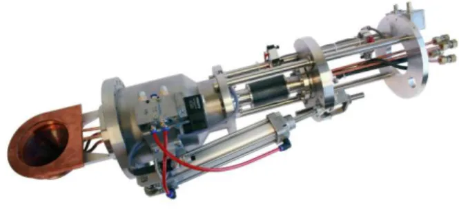
Destructive Beam Intensity Measurements
They are carried out by copper made water cooled Faraday Cup in the L.E.B.T and in the M.E.B.T. (end of the line). The first one following the E.C.R. ion source is specially devoted to the tuning of the source. The Faraday cups are designed for a 100 mm aperture in the LEBT and 60 mm in the M.E.B.T. The maximum beam power
Figure 2: Photograph of the Faraday Cup of the L.E.B.T.
Proceedings of DIPAC09, Basel, Switzerland MOPD27
01 Overview and Commissioning
0,00E+00 1,00E+02 2,00E+02 3,00E+02 4,00E+02 5,00E+02 6,00E+02 7,00E+02 8,00E+02 9,00E+02 1,00E+03
0,00E+00 5,00E+00 1,00E+01 1,50E+01 2,00E+01 2,50E+01 3,00E+01 3,50E+01
temps (s) tem p er atu re (K ) wire : Tungsten intensity: 5 mA Energy :1.5 MeV wire diameter :150 μm cycle : 0.5 ms/s beam diameter: 2 cm
sustained by the Faraday Cup is then 1.2 kW ( LEBT) and 1.5 kW (MEBT) corresponding to a maximum temperature of 350° K (MEBT). The design has been optimized by thermal simulation under ANSYS software.
Non Destructive Beam Intensity Measurement
A D.C.C.T. (New P.C.T. from Bergoz Company) is located just at the entrance of the R.F.Q. in the L.E.B.T. A home made three layers shielding (Armco, mu metal and copper) protects the sensor from the external leakage magnetic field solenoid.
Extensive tests have been carried at Ganil to check the sensitivity of the D.C.C.T. in the vicinity (7 cm) of the leakage field of a solenoid. It has been measured that the shielding lowers the offset drift from 1 µ A/Gauss down to 0.1 µA/Gauss. Results concerning the other main parameters such as bandwidth, drifts with temperature, linearity are in good agreement with the nominal manufacturer specifications.
An A.C.C.T. will be coupled with a D.C.C.T in the M.E.B.T. line in order to fulfil all the foreseen mode of operation of the accelerators. An identical couple of transformers will be installed at the exit of the LINAC to
measure as accurately as possible (≤ 1%) the LINAC
efficiency transmission. These measurements are required for safety reasons during the daily operation.
Transverse Beam Profiles Measurements
Even during low duty Factor pulse beam operation, SPIRAL2 beams deposit a large amount of energy in any
sensor and may reach several hundred W/cm2 in the
LEBT. The evolution of the temperature has been estimated by a crude resolution of the heat equation. An example is given in Fig. 3 in the case of a 150 µ m diameter tungsten wire impinged by a 2 cm diameter, 5 mA, 1.5 MeV proton beam, pulse duration: 500 µs, repetition rate: 1 s. The average temperature reaches nearly 900° K after 1 s.
Figure 3: Evolution of the temperature of a 150 µm diameter tungsten wire (see text).
The grid of the sensors is divided in to two categories according to the beam size to be measured: 47 wires of 150 µm diameter tungsten with a spacing of 1 mm for the
Figure 4: View of the secondary emission beam profiler. first one and 47 same diameter tungsten wires (spacing is variable from 1 mm up to 3 mm) for the second category [2]. These wires are welded on an alumina board to obtain
a maximum out-gassing rate of 1.10-8 Pa.m3.s-1.
The complete tuning of the beam transport in the L.E.B.T. needs 16 secondary emission beam profiler (variable spacing) and 4 (spacing 1mm) for the M.E.B.T.
Transverse Beam Emittance Measurements
The full transverse characterisation of the beam needs to measure the transverse beam emittance. Water cooled scanner emittancemer also named Allison Scanner has been selected. It is schematically depicted in this Fig. 5.
Figure 5: Schematic of the Alison emittancemeter of the L.E.B.T. and M.E.B.T.
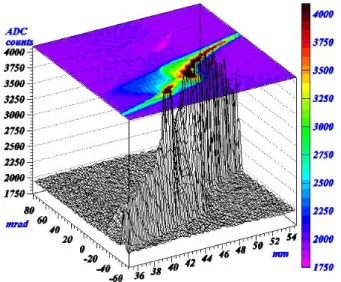
Figure 6: Ion beam emittance measured at the exit of the SPIRAL2 Phoenix source. Beam: Ar 4+, 60 KeV, 15 µA.
MOPD27 Proceedings of DIPAC09, Basel, Switzerland
01 Overview and Commissioning
The beam current impinges on the narrow slit (width: 0. 2 mm) of the scanner pod. The emerging beamlet passes between a pair of electric deflection plates driven by a linear ramp generator: ± 1.4 kV max (LBET) and ± 4 kV max (M.E.B.T.). For ions passing through the rear slit there is a simple relationship between the initial angle and the instantaneous ramp voltage. The maximum measurable angles are ±100 mrad (L.E.B.T.) and ± 30 mrad (M.E.B.T.). The scanner pod is stepped across the beam to complete the measurement as a function of x and x’ (full stroke: 120 mm in the L.E.B.T.). The intensity of the beamlet is measured at each step of the pod.
The prototype of the emittance-scanner has been already tested on the ion source to be installed on SPIRAL2. The result is shown on Fig. 6 in the case of Ar 4+ beam.
Longitudinal Measurements
A fast coaxial Faraday cup, previously used on the Intermediate Test Bench (B.T.I.) will be installed in the M.E.B.T. following the commissioning to measure the bunch lengths. A Fast Faraday cup is under design in collaboration with a manufacturer. This new design may allow the Faraday Cup to withstand a 400 W beam power and the bandwidth is expected to reach 2 GHz in order to measure accurately the bunch length (rise time < 200 ps). This Fast Faraday Cup will be tested at Ganil during the last quarter of this year.
A Fast Current Transformer (upper cut-off frequency: 1.6 GHz) will be installed in the M.E.B.T. upstream of the Linac for beam phase measurements.
COMMISSIONNING OF THE SPIRAL2
INJECTOR
The first step of the commissioning of the SPIRAL2 injector consists to install in the French C.N.R.S. laboratory “L.P.S.C.” located at Grenoble, the E.C.R. ion
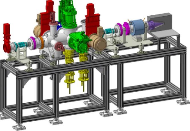
Figure 7: 3D view of the Intermediate Tests Bench (B.T.I.).
source followed by the first part of the ion L.E.B.T. in order to check the operation of the source at the nominal
beam power and to test the behaviour of the diagnostics: Faraday cup, beam profiler, emittancemeter.
In a second step, following the installation of the injector at GANIL, an “Intermediate Tests Bench” named B.T.I. will be assembled as part of the injector commissioning plan. The B.T.I. will be positioned directly after the first re-buncher of the M.E.B.T in order to fully characterize the following beam properties:
• Beam current: D.C.C.T. and A.C.C.T.
• Beam transverse profiles: Secondary emission
monitor and residual ionization gas monitor in order to compare the obtained profiles.
• Transverse emittance.
• Longitudinal emittance: Measurement of the bunch
length variation with a fast Faraday cup against the variation of the voltage of the re-buncher.
• Phase and energy: A classical arrangement of three
P.U. electrodes determines the number of bunches and the energy by time of flight.
• Beam Position: Two Beam Position Monitors will be
a copy of the Linac P.U. (length: 39 mm, inner diameter: 48 mm, subtented lobe angle: 60°). Their primary function is to steer the beam to the beam stop. The latter will be used to measure the phase and the beam energy using the time of flight method (cross-check with the previous measurement). All the diagnostics used on the B.T.I. will be identical to the accelerator ones. The non-intercepting measurements can be made at nearly full duty factor as the beam stop is planned to withstand the beam full power of the M.E.B.T. A second set of measurements with the B.T.I. positioned just downstream of the third re-buncher of the M.E.B.T. is planned.
CONTROL SYSTEM OF THE INJECTOR
EPICS has been selected for the SPIRAL2 control system and therefore for the SPIRAL2 injector. Consequently the architecture is based on industrial adapted solutions VME cards to control the different devices. The EPICS drivers have already been written.
REFERENCES
[1] T. Junquera & al, the high intensity superconducting Linac for the SPIRAL2 project at Ganil, Proceedings of LINAC06, Knoxville, Tennessee USA
[2] P. Bertrand, JL Biarrotte and D. Uriot, Beam dynamics studies for the Spiral2 project, Proceedings of EPAC06, Edinburgh (UK) 2006.
[3] W. Le Coz & al, phase and amplitude measurement for the spiral2 accelerator, this workshop DIPAC 2009, Basel, Switzerland
[4] J.L. Vignet & al, the beam profile monitors for Spiral2 accelerator, this workshop DIPAC 2009, Basel, Switzerland
Proceedings of DIPAC09, Basel, Switzerland MOPD27
01 Overview and Commissioning