HAL Id: hal-01738114
https://hal-ifp.archives-ouvertes.fr/hal-01738114
Submitted on 20 Mar 2018HAL is a multi-disciplinary open access
archive for the deposit and dissemination of sci-entific research documents, whether they are pub-lished or not. The documents may come from teaching and research institutions in France or abroad, or from public or private research centers.
L’archive ouverte pluridisciplinaire HAL, est destinée au dépôt et à la diffusion de documents scientifiques de niveau recherche, publiés ou non, émanant des établissements d’enseignement et de recherche français ou étrangers, des laboratoires publics ou privés.
Assessment of Retention Processes for Transport in a
fractured system at Äspö (Sweden) Granitic Site: from
Short-Time Experiments to Long-Time Predictive
Models
Christophe Grenier, Andre Fourno, Emmanuel Mouche, Hakim
Benabderrahmane
To cite this version:
Christophe Grenier, Andre Fourno, Emmanuel Mouche, Hakim Benabderrahmane. Assessment of Retention Processes for Transport in a fractured system at Äspö (Sweden) Granitic Site: from Short-Time Experiments to Long-Short-Time Predictive Models. Dynamics of Fluids and Transport in Fractured Rock, Geophysical Monograph Series, 2005. �hal-01738114�
Assessment of Retention Processes for Transport in
a fractured system at Äspö (Sweden) Granitic Site: from Short-Time
Experiments to Long-Time Predictive Models.
Christophe Grenier, André Fourno, Emmanuel Mouche
Commissariat à l'Energie Atomique. Centre d'Etudes de Saclay. Gif sur Yvette. France
Frédérick Delay
Université de Poitiers. Laboratoire Hydrasa. UMR 6532 du CNRS. Poitiers. France
Hakim Benabderrahmane
Agence Nationale pour la Gestion des Déchets Radioactifs. Châtenay-Malabry. France We present results obtained within Task 6 modelling project hosted by SKB (Swedish Nuclear Fuel and Waste Management Company) Task Force on Numerical Modelling of Flow and Solute Transport in fractured granitic rock. Modelling the transport of the radionuclide in natural fractured media aims at characterizing and assessing the performance of a potential deep geologic repository. Task 6 modelling exercise objective is to provide a bridge between models based on detailed site investigation data and calibrated against tracer experiments (month scale) and models corresponding to a hypothetical repository post-closure time scale (hundred thousands of years). Latter models capture the most significant features and processes and allow for a sensitivity analysis of uncertain parameters. Two features involved in tracer experiments (TRUE-1 and True Block Scale-TBS) were studied. The first is a 10 m single fracture while the second is a 200 m semi synthetic fractured block. The study focused on matrix zone heterogeneity, their influence on the retention processes and their level of identification from tracer tests. Results show that tracer tests poorly constrain the systems. A model suited for Performance Assessment was built for the single fracture geometry. A smeared fracture approach to model transfers in a fractured block is presented. The approach is qualified and validated on synthetic test cases and applied to Task 6 fractured block. Results show that it is appropriate for Performance Assessment time scale purposes. Nevertheless, the approach would require further developments to be applied to systems incorporating lower scale heterogeneities under experimental conditions.
1 INTRODUCTION
Within the framework of nuclear spent fuel storage, special concern is put on experimentation and modelling work to improve the modelling capabilities for the transfers of radionuclides within natural fractured media (refer to [GEOTRAP, 2002; Chapman and McCombie, 2003]). The transit time for different tracers into the host geological medium indeed qualifies the efficiency of the storage. Several aspects make this modelling work a challenging task, among which are the geometrical variability of the system, the scarcity of available data, the strong contrasts in the parameter values between mobile and immobile zones (see e.g. [Bear et al., 1993]). An additional difficulty is related to the fact that the experimental programs necessarily provide a view into the
system for transfers over short distances and time scales, although for Performance Assessment, predictions are required over much longer distances and time scales (typically kilometric and 100.000 years).
In granitic media the flow mainly occurs along fractures due to the low conductivity of the matrix blocks. Thus, the fractures appear as the main transfer paths for radionuclides towards the
geosphere. Transfer in those more or less complex conductive units is advective and dispersive. Nevertheless, interactions with the rock matrix and/or stagnant zones limit the velocity or
importance of these transfers. One of the key retention processes to be considered for transfer into low permeability formations is diffusion into immobile zones: fractions of the plume are temporally retained from the main flow paths by diffusion into rock blocks (porous portions of the rock with negligible flow, fracture infilling materials, depositions onto fracture walls, dead end pores …). This process is classically referred to as matrix diffusion effect [Neretnieks 1980; GEOTRAP, 2002]. The importance of this phenomenon increases as the diffusion coefficient values increase but as well with the contact time with the plume. For a post closure situation (natural flow and repository installed within low conductivity zones) the velocity of the water is very slow. As a consequence, matrix diffusion should be important. One may refer to our previous contributions [Grenier et al., 1998; Grenier et al., 1999].
We provide below results obtained within the SKB Task Force focusing on different issues associated with the Äspö site (Sweden) and using the associated database. This site is one of the best characterized and documented areas providing unique opportunities for realistic modelling exercises. Several international exercises were organised over the last decade within the Task Force to assess the different issues associated with nuclear waste storage. They took advantage of the rich Äspö granitic database and addressed issues related to flow and transport modelling at local or regional scales. One may refer to ASPO-TF for more details and [Grenier and Benet, 2002;
Grenier et al., 1999] for some of our previous work. The current research and development
program of SKB provides as well a background to the task (see [SKB, 2004]). The main objective of present task is to build a bridge between Site Characterization (SC) models and Performance Assessment (PA) models. The first type of models are complex, incorporating detailed physical and geochemical properties and calibrated on or constrained by short term and small scale in situ
experiments. Performance assessment models can be simpler, restrained to the main physical features, generally used to address uncertainties by simulating a range of possible configurations and parameter values. They apply to long time ranges as well as larger spatial scales.
Two modelling scales are considered: a single fracture case ((Feature A, part of TRUE-1, Tracer Understanding Experiment, extension roughly 10 m) and a semi synthetic 200 meter block consisting of different levels of fracturation, from larger scale deterministic features (100m) to roughly 5600 smaller scale synthetic features (meter scale). The larger scale features were actually measured from the block and referred to as deterministic features below (TRUE Block Scale project), the lower scale features were simulated according to the statistics of the fracturation obtained from measurements at the site. Tracer tests were conducted within the block at Äspö in fully saturated flow conditions. Tracers range from non sorbing to moderately sorbing.
Breakthrough curves show restitution for a monthly time scale. For the block scale model,
deterministic features (in situ observations) explain the behaviour of the tracer well enough. These tracer tests are initially considered as a common basis for the modelling. Predictions are then proposed for post closure conditions (thousands of years, PA time scale). Single fracture study was considered as a first step prior to fractured block scale, a more pertinent system to actually address the practical issue of storage in granitic media.
We present here results we obtained within this task. We first sum up the main results from the single fracture study. Then we present a novel type of smeared fracture approach for transfers in a fractured block and the calibration results based on the tracer tests data.
Tracer tests and modelling strategy
Tracer tests are conducted under radial (pumping) conditions providing maximal recovery. Tracers range from non sorbing to intermediate sorbing. Predictions involve similar radial flow for 1000 times lower flow rates as well as natural uniform flow (gradient by 0.1%).
Several modelling approaches were conducted by the different teams participating in the SKB Task Force with methods ranging from discrete to continuous ones. We limit here the presentation to our own results and conclusions. We focused our study on the issue of retention processes resulting from the presence of heterogeneous matrix zones along the flow path. We considered several potential representations of the heterogeneity of the system ranging from simple deterministic homogenous matrix models to complex stochastic heterogeneity. Detailed measurements available at Äspö indeed provide a refined representation of these zones (see Fig. 1, Tab. 1 and below). One can also refer to [Grenier, 2004] for more details.
Matrix zones Extent (cm) Porosity (%) Diffusion coefficient (10-10 m2/s) Fault gouge 0.5 20 5. Fracture coating 0.05 5 2. Mylonite 2. 1 1. Altered Diorite 20. 0.6 0.8 Non altered Diorite - 0.3 0.5 Table 1: Parameters associated with the different matrix zones (Depth of the zone, porosity and pore diffusion coefficient).
Figure 1: Conceptual model of the fractured zone (after Dershowitz et
al. 2003).
We briefly specify that our continuum modelling approach is implemented within the Cast3m code, developed at CEA (Commissariat à l’Energie Atomique), based on a mixed and hybrid finite element scheme for flow and transport equations (see [Dabbene, 1998; CAST3M; Mosé et al., 1994]). This discretization scheme ensures mass conservation for each element of the mesh. It is particularly interesting in applications considering heterogeneous media as contemplated here. The radial or uniform structure of the flow is incorporated. The different units and subunits of the system are explicitly meshed or modelled with a smeared fracture approach presented below. For sake of illustration, we show explicitly here the transport equations for a single fracture and homogeneous matrix. The equation governing flow in the fracture is Darcy law. Matrix zones have much lower permeability and are considered here as no flow zones. These include as well fracture gouge or infilling materials treated as no flow zones only accessed by diffusion. The eulerian transport equation is expressed below for 1D transport in the fracture (x direction) as well as 1D orthogonal (y direction) matrix diffusion (see [Maloszewski and Zuber, 1985; Bear et al., 1993):
0 2 2 = ∂ ∂ − ∂ ∂ − ∂ ∂ + ∂ ∂ =b y m m m f f f f y C b D n x C D x C v t C R (1) 0 2 2 = ∂ ∂ − ∂ ∂ y C D t C R m m m m (2)
The first equation considers advective transport for concentration in the fracture (Cf) considering
that the fracture is fully open with unit porosity, with v for Darcy velocity, D for
dispersion/diffusion coefficient. The loss of mass towards the matrix is proportional to the gradient of the concentration in the matrix at the fracture wall (distance b along axis y corresponds to half fracture aperture, nm is matrix porosity, Dm is matrix pore diffusion coefficient). Linear sorption
effects onto the fracture walls are accounted for by the retardation term Rf. Transport in the matrix,
second equation, corresponds to a purely diffusive term (Dm) and linear bulk sorption accounted for
by the retardation term Rm. The boundary condition is imposed fracture concentration. Matrix
diffusion acts as a sink/source term in Eq. 1 slowing down progression of mass in the fracture.
2 MAIN RESULTS FROM SINGLE FRACTURE CASE
We focused our study on the following issues: (i) role played by the different matrix zones for different flow regimes (Site Characterization and Performance Assessment time scales), (ii) level of information provided by tracer tests, (iii) building of a simplified model for PA time scale, (iv) analysis of the information contained in tracer test breakthrough curves for PA time scale purposes, (v) identification of main measurement required for this prediction regime.
Matrix diffusion as a retention process is largely described in the literature. [Carrera et al., 1998] sum up the major properties of the system based on breakthrough curves: for low matrix diffusion, peak arrival time is weakly delayed, peak level slightly decreases and a long tail appears. For large matrix diffusion effects, the breakthrough curve is strongly delayed. An important remark is that for such a regime, the shape of the curve is closer to symmetrical. The system is then indeed equivalent to a simple advection dispersion system involving a retardation coefficient. The velocity of the plume is controlled by the total porosity (incorporating the matrix zone volumes) as discussed by [Neretnieks, 1980] or [Ostensen, 1998].
We studied transport regimes associated to the different matrix zones measured from Feature A (single fracture) and extended the former results by [Ostensen, 1998] to heterogeneous matrix systems (similar to Fig. 1 configuration).
For the first transport regime (SC conditions or low matrix diffusion) and the simple single matrix zone geometry (see equations (1) and (2)), a [square root of time] parameter controlling matrix diffusion is provided by [Maloszewski and Zuber, 1985]:
f m m m bR D R n a 2 1= − . (3)
a-2 corresponds to a characteristic time of diffusion between fracture and matrix. For more than one matrix zone, the influence of the matrix is expressed in terms of an averaged a coefficient. The average applies to properties of the zones explored by the plume during the tracer test, i.e. the zones in the vicinity of the flow path. In the present case (see Fig. 1 and Tab. 1), these zones correspond to stagnant water pores, fracture coating, fracture infilling (and to a lesser extent high diffusion zones like Mylonite).
For the second transport regime (PA flow conditions and high matrix diffusion), the parameter controlling the velocity of the plume is derived in terms of a retardation coefficient (for i indexing the matrix zones, di associated depths):
∑
+ = i mi i mi f n dR b R 2 1 1 ' . (4)Indeed, our simulations confirm that for large matrix diffusion coefficients or equivalently slow flow regimes typical for PA conditions, the system behaves as a single porosity system equivalently described by a simple advection dispersion equation with a corrected retardation coefficient.
Application to heterogeneous matrix properties as seen on Fig. 1 shows that the most diffusive matrix units adjacent to the flow path are similarly filled up almost instantaneously as compared to the advective travel time in the fracture. This means that these units behave as simple buffers so
that the total volume experienced by the plume is not limited to the fracture but includes
surrounding high diffusion matrix zones. These are for the present case fracture infilling, fracture coating, stagnant water, Mylonite (refer to Fig. 1). Considering the average properties associated with the various matrix zones (see Tab. 1) and for non sorbing tracer, R’f is of the order of 10. The
other matrix zones located more in the depth of the matrix blocks (altered and non altered granite) still represent diffusion zones providing transient storage of the solute. They can’t be similarly homogeneized but require explicit modelling.
As a consequence, building a simplified representation of the system for PA time scale is
straightforward. The heterogeneity of the matrix falls into two categories: highly diffusive matrix zones adjacent to the flow path and lower diffusive zones (altered and non altered granite). The first class of heterogeneity boils down to a modified fracture property R’f (Eq. 4). The other zones have
to be explicitly modelled as matrix diffusion zones (here composite altered and non altered granite). Nevertheless, our simulations show that for the system studied (see Tab. 1 and for PA time scales considered) the most diffusive zones represented as R’f actually control the peak arrival time of
breakthrough curves. Other matrix zones (altered and non altered granite) have secondary influence on peak arrival time but more introduce lower peak level and tailing effect. As a consequence, we propose a PA model represented by an equivalent fracture (R’f) and homogeneous or composite
matrix zones. Furthermore, considering that the properties for altered and non altered zones do not strongly differ (see Tab. 1), this PA model can be limited to homogeneous matrix (e.g. with average properties). The final model is very simple. It formally corresponds to the system of Eq. 1 and Eq. 2 where fracture properties involve R’f and matrix properties correspond to the average properties of
granitic zones. Analytical solutions exist for this system (see e.g. [Maloszewski and Zuber, 1985]). Another consequence of these results can be drawn along the line of inverse problem (identification of properties) based on tracer tests. Breakthrough curves only provide a view on averaged matrix properties along the flow path. Moreover, these properties are expressed in terms of a parameter. Due to the fact that parameter requirements for (PA) long time scale predictions involve parameter group R’f (see Eq. 4), no direct use can be made of the information obtained in terms of a parameter
from tracer tests unless independent measurement of the different properties associated with the matrix zones is provided. This was previously stated by [Ostensen, 1998] for applications to the WIPP site (USA). Moreover, the penetration depth of the plume is larger for PA time scale. This means that short term tracer tests do not provide any kind of information about these deeper zones. As a conclusion, tracer tests poorly constrain the system at PA time scales.
For PA purposes, the level of realism can be increased based on direct measurements of matrix heterogeneity ((geo)statistical information about the porosity and geometry of these zones). Practically speaking we checked that a model schematically incorporating the structure of Fig. 1 and the values from Tab. 1 fitted the experimental breakthrough curves. This level of heterogeneity corresponding to the best knowledge available was used for the predictions at PA time scales and we showed previously how this model can simplify to the simple system represented by Eq. 1 and 2 with ad hoc parameters.
Nevertheless, one of the major remaining uncertainties is related to the flow field. The flow path during tracer test remains uncertain. In ambient flow conditions, the flow paths may become even more complex between source and outlet.
The studies conducted on a single fracture system (Feature A) constitute the first part of Task 6. It is considered as a building block for the second part involving a 200 m fractured block.
3 SMEARED FRACTURE APPROACH
Modelling flow and transport within a realistic fractured block requires an appropriate modelling strategy as well as associated numerical tools. The 200 m semi synthetic block specified within the
task consists of over 5600 features covering several scales of fracturation (see [Dershowitz et al., 2003]). The system can be roughly divided into major conductors which were explicitly measured at the site (typically several decameters) and background fracturing simulated according to
statistical measurements. Moreover, each of these conducting units is associated with more information in form of a complexity factor providing insights into its structure. These indeed actually consist of smaller fissures with distributed alteration patterns. Such a complex system cannot be modelled explicitly incorporating all details. This is due to computer constraints as well as uncertainties associated with previous patterns. Some level of simplification or homogenization is required and is finally superimposed to the major conductors.
3.1 Presentation of the smeared fracture approach
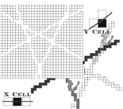
Our general approach to the modelling of transfers in the block consists in a representation by means of a smeared fracture approach: the larger structures (modelled here) are not explicitly meshed (requiring sophisticated dedicated mesh generator) nor represented by 1D links (discrete fracture network assuming 1D orthogonal diffusion); the basic idea of the method is to take the presence of these units into account by means of a heterogeneous field of properties applied on a regular grid. A conductor is represented as a connected number of high permeability elements (see Fig. 2). Equivalent properties are associated to the cells providing exact modelling of the total hydraulic and transported mass flux for each fracture as compared with its discrete representation. In addition to this explicit modelling of major conductors, minor features or heterogeneity patterns could be included as equivalent single or double porosity models.
Figure 2: Principles of smeared fracture approach.
The advantages of this approach follow: (i) No dedicated meshing is necessary. The 3D geometry of matrix blocks is accounted for; (ii) the grid (constant mesh size) actually represents the
simulation scale (Representative Elementary Volume). The smaller heterogeneity structures are homogenized to grid properties. An appropriate choice of the grid size generally results into lower computer requirements than explicit modelling of the features provided; (iii) the method is very versatile: smaller or larger number of conducting features can be easily taken into account as well as presence of background fracturing or fracture complexity; (iv) uncertainties associated with the properties is easily addressed by means of Monte Carlo simulation taking benefit from the
versatility of the method and associated low computer costs. Extension to heterogeneous subsystems is straightforward.
Nevertheless, this approach presents some drawbacks. They appear with coarse grids and are mainly: (i) insufficient geometrical precision in the description of the conducting units and their intersections; (ii) low numerical quality of the simulation due to the fact that fractures and matrix blocks presenting large contrasts in the transfer properties are potentially badly represented by a
single grid size and time increment. As such, the method is more specially adapted for PA time scale for which diffusive processes are important (smoothing directional effects along fractures). In order to identify these limitations, the method was qualified and its validation range was studied on 2D and 3D systems. We provide below a more detailed introduction of our smeared fracture approach as well as its implementation in our Cast3M code, its validity range and qualification of the results.
3.2 Background and approach
The basic idea is to account for the presence of fractures by means of continuous heterogeneous fields (permeability, porosity, head, velocity, concentration...) on a regular grid. This line, followed by different authors (see e.g. [Svensson, 2001; Tanaka et al., 1996]), is referred to as Smeared Fracture approach. It is developed here for a mixed hybrid finite element scheme [Dabbene, 1998;
Mosé et al., 1994], considering each single feature and accurate fluxes.
The first step involves identification from the regular grid of elements corresponding to the presence of a fracture (see Fig. 2 for a 2D example). In a second step, equivalent properties are associated with these elements to accurately account for the fluxes in this unit. For an angle θ fracture between the fracture and the horizontal direction, the equivalent permeability is:
ref sf K x e K ∆ + = 3 ) sin cos 3 ( θ θ , (5)
where Ksf is the smeared fracture value, Kref, the measured fracture transmissivity, e and ∆x are
respectively fracture aperture and grid size. These expressions result from mixed and hybrid finite element scheme applied to a single fracture. Exact conservation of flux is obtained. For a fracture network, the same procedure is applied for each conductor. At fracture intersections the
permeability is set to the maximum value from all the branches. We consider full mixing at the fracture intersections. The smeared fracture approach is here limited to steady state flow and transient eulerian transport (advection, dispersion, diffusion). Equivalent properties are derived similarly for dispersion, porosity and diffusion associated with each single fracture (see [Fourno et
al., 2004]).
3.3 Qualification and range of validity of the method
As stated, slight discrepancies in the calculation for fractured networks are introduced by the treatment of fracture intersections. Other sources of inaccuracy originate from matrix diffusion effects. As a consequence, a series of tests have been set up to study the precision of the approach for (i) different geometries (2D and more recently 3D) ranging from simple to realistic, for (ii) different space and time discretizations, (iii) different flow and transport regimes (depending on fractures and matrix properties, and flow velocities: from forced flow to natural gradient
conditions).
We briefly illustrate the validation and qualification efforts made for a single fracture case for different flow regimes. The velocity of the flow in the fracture determines the contact time of the plume with matrix zones. The lower the velocity the larger is the retention processes due to matrix diffusion. Three cases are considered ranging from low matrix diffusion effect (leading to tailing effect but negligible delay in the peak arrival time) to large retention effects (corresponding to strongly delayed peak). Breakthrough curves associated with the different regimes are provided on Fig. 3. Sensitivity to the grid size was studied for these different regimes. They are represented for the two extreme regimes on Fig. 4 and Fig. 5. The reference calculation (upper curve in both cases) is obtained from explicit meshing of the different units.
Figure 3: Breakthrough curves for 3 fracture flow regimes: quick arrival and narrow curve to delayed arrival and large spread.
Figure 4: Sensitivity of breakthrough curve to grid size for single fracture case: quick regime.
Figure 5: Sensitivity of breakthrough curve to grid size for single fracture case: slow regime.
Results show that (i) the more refined the discretization, the closer to the reference simulation, (ii) for high velocities in the fracture, the penetration depth in the matrix is limited so that the matrix is too roughly discretized for most grid size; for a lower velocity in the fracture, that is for transport regimes mostly controlled by matrix diffusion, results are not very sensitive to the size of the grid. This example allows for determining the range of application of the method in terms of grid size:
2 2 6 1 1 " : , " 3 . 0 b t D n R with t R R D x m m w w m m = + < ∆ . (6)
tw stands for water transit time. R” estimates the retardation of peak arrival resulting from matrix
diffusion on a simple fracture matrix system [Neretnieks, 1980]. The expression for ∆x is derived from a Fourier coefficient expression. It confirms the intuition that the method indeed performs well for post closure regimes (low natural gradients in storage zones). The reduction in simulation time is roughly 70%.
Other results not presented here [Fourno et al., 2004] show that the method performs well in terms of precision for flow and transport limited to the fracture network, even for a coarse discretization. The main limit in the grid size is mostly related with geometrical considerations (digitalisation of the fracture network geometry should be fair). Recent results show that these conclusions can be extended to 3D systems.
4 RESULTS FROM INVERSE PROBLEM ON TRACER TESTS CONDUCTED AT BLOCK SCALE
We present briefly Task6D, a further step of the Äspö Task Force to the 200 m bock scale. The goal of Task6D corresponds to the identification of properties of the system from tracer tests conducted within the block. We present here our modelling strategy and the results obtained for the inverse problem as well as its relevance for PA time scale predictions.
4.1 Presentation of tracer test and modelling strategy
A series of tracer tests was performed in the fractured block in the Äspö Underground Laboratory at the Block Scale location (see [Dershowitz et al., 2003]). The pathway involves 4
deterministically identified structures numbered 23 (injection), 22, 20, 21 (pumping location). The distance through the four features from injection to pumping borehole is roughly 100 meters, corresponding to a cartesian distance of 17 meters. Four tracers are considered for Test C2 and breakthrough curves are provided: non sorbing Iodine, slightly sorbing Calcium-47, moderately sorbing Barium-131, strongly sorbing Cesium-137. The input pulses extend over tens of hours. Here, we limited our efforts to perform an optimal deterministic calibration of the system associated with a sensitivity analysis to the main features. Indeed, due to large uncertainties on geometry and properties of both flow paths and matrix zones, the inverse problem is largely underdetermined. Uncertainties in the flow path are related to probable complexity of the deterministic fractures, actual geometry of these conductive structures (including intersections), presence of non identified background fracturing. Uncertainties in the matrix zone properties correspond to the points mentioned previously for the single fracture case.
Results obtained from the previous single fracture study showed that tracer tests give merely an averaged view on the matrix zones properties in the vicinity of the flow path. Moreover, this is right only when the travel path is well identified. For the present block scale test C2, the
uncertainties in the flow and matrix zone properties are even higher. This makes tracer tests almost useless for prediction purposes. As a consequence, Test C2 calibration is a simple assessment of the coherence of the global knowledge of the site and the associated data base (geometries, properties, tracer tests …). This is here more a step in increasing the level of confidence in the modeled system rather that gaining actual information from tracer tests.
We present now our modelling strategy. We consider two models underlying the calibration procedure, a global and a local model. A global 200 m smeared fracture model including deterministically identified structures is represented on Fig. 6.
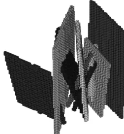
This steady flow model under pumping conditions provides boundary conditions to the local model. The local 3D model explicitly representing 4 features (20 to 23) as well as adjacent matrix is
provided on Fig. 7 and serves for calibration of breakthrough curves. The pumped flow rate is large enough to yield high velocities and hence a penetration depth into the matrix is limited to a few decimetres. The Smeared fracture approach was not considered for the local 3D model since it does not provide optimal precision for short term tracer tests as presented previously. One should
consider a small grid size (compatible with the penetration depth) which would imply high computational costs. Further developments of the approach are contemplated and will circumvent this by a kind of dual porosity approach to this local matrix diffusion (see e.g. [Grenier et al., 1999]). Here, we in fact explicitly meshed the four (planar) fractures as well as their intersections and adjacent matrix volumes (see Fig. 7). The calibration procedure was conducted on this smaller system allowing for low computational costs. Homogeneous properties are associated to the adjacent matrix volumes. We indeed stated before that tracer tests don’t allow for identification of heterogeneous properties but rather an averaged property.
Injection
Pumping
Figure 7: Explicit 3D meshing of Fractures 20 to 23 as well as surrounding matrix zones.
4.2 Results
The calibration procedure consists in providing a best fit (visual judgement) for all the tracers considered. We allow for identification of a single matrix property (in terms of a coefficient involving diffusion coefficient and porosity) corresponding in reality to an average property associated with the actual heterogeneous matrix zone visited by the plume. The breakthrough curves are satisfactorily matched for the simple model considered. Experimental breakthrough curves are provided on Fig. 8 as dots, calibrated models are represented as lines for the tracers injected. Additional Radium-226, Technecium-99 and Americium-241 are provided for the same input curve as for Cesium-137. The values of the calibrated parameters well fall into the expected ranges (porosity of 2% and pore matrix diffusion coefficient of 2.10-10 m2/s), roughly
corresponding to a mix between gouge and high diffusion zones (fracture coating, fracture infilling, partly Mylonite, refer to Tab. 1). Overall coherence of the model is asserted.
Sensitivity analysis to the different sub units of the model show that the properties associated with transit time in the fracture sub unit are of major importance. Indeed, travel path length, fracture transmissivity and aperture are dominantly responsible for the peak arrival time. Matrix diffusion plays here a relatively secondary role leading to clear tailing effect but little delay in the peak
arrival time. Due to the radial structure of the flow, the matrix zones in the vicinity of the injection have the larger impact on the breakthrough curves.
Figure 8: Breakthrough curves for the tracers considered (dots for experimental and solid lines for simulations).
5 CONCLUSIONS AND PERSPECTIVES
Results show that only a limited identification of fractured medium properties by tracer tests is possible. This is due to the large heterogeneity of the system and the fact that tracer test provide an averaged view of the zones explored but no particular identification of each unit. Conducting tests with different flow velocities could not improve significantly the characterization of these zones. The main uncertainties are basically related with underlying flow properties (spatial distribution for instance) requiring further characterization and modelling work to improve the knowledge
associated with these patterns. Moreover the identification problem is considered in view of predictions of transfers at PA time scale (several thousands of years). Results show that (i) the zones identified from tracer tests are very close to the flow path whereas matrix zones implied by PA time scale are located more in depth and are not characterized; (ii) the parameters identified from tracer tests are not the ones required for this time scale due to differences in transport regimes. This is true for the single fracture system as well as for the block scale system, the uncertainties for the latter being even larger. For PA time scale one should as a consequence rely upon direct
measurements of the heterogeneity structure of the fractured system and characterisation of the flow field.
Matrix zones can be sorted into two distinct behaviours for PA time scale. The resulting PA model is very simple. The retention effects are most related with high diffusion and porosity zones close to the mobile zones, leading to strong delays in the peak arrival times.
Smeared fracture approach proved to be efficient in modelling flow and transport in fractured networks. The levels of precision are high even for rather coarse meshing. Results show that the approach performs well for post closure time scales. For experimental time scales, the penetration of the plume is very limited to the close vicinity of the conductors and the approach in its present state is not adapted. Additional work is required to cope with this quick transport regime as well as to account for other sub grid heterogeneities. This is contemplated in the future based on a type of dual porosity approach (see [Grenier et al., 1999]).
References
• ASPO-TF web site for the Äspö Task Force under http://www.skb.se/templates/SKBPage____2636.aspx
• Bear J, Tsang CF, de Marsily G (Editors), Flow and contaminant transport in fractured rock, Academic Press. 1993.
• Carrera J, Sanchez Vila X, Benet I, Medina A, Galarza G, Guimera J, On matrix diffusion: formulations, solution methods and qualitative effects. Hydrogeology Journal 6:178-190, 1998.
• CAST3M web site under http://www-cast3m.cea.fr/cast3m.
• Chapman N, McCombie C, Principles and standards for the disposal of long lived radioactive wastes. Waste Management Series. Elsevier, 2003
• Dabbene F, Mixed Hybrid Finite Elements for transport of pollutants by Underground Water. Proceedings of the 10th International Conference on Finite Elements in Fluids. Tucson, Arizona, USA. January 5-8, 1998.
• Dershowitz W., Winberg A., Hermanson J., Byegard J., Tullborg E.-L., Andersson P., Mazurek M., Äspö Task Force on modelling of groundwater flow and transport of solutes – Task 6C – A semi synthetic model of block scale conductive structures at the Äspö HRL. International SKB Progress Report IPR-03-13. 2003.
• Fourno A., Grenier, C., Delay F., Mouche, E., Benabderrahmane, H., Smeared fractures: a promising approach to model transfers in fractured media, Proceedings CMWR’04, Chapel Hill (USA), 2004
• GEOTRAP, Radionuclide retention in geologic media. Workshop proceedings. Oskarshamn, Sweden, May 2001. OECD/NEA, 2002.
• Grenier C., Modeling transfers in a single fracture system: From site characterization to performance assessment models. Contribution to Task 6A and 6B from Äspö modelling task force exercise. SKB international Cooperation report, IPR04-37. 2004.
• Grenier C., Benet L.-V., Groundwater flow and solute transport modelling with support of chemistry data, Task 5, Äspö Task force on groundwater flow and transport of solutes, SKB International Cooperation Report, IPR-02-39. 2002.
• Grenier C, Genty A, Mouche E, Tevissen E, Modelling matrix diffusion in fractured media : from single fracture scale to block scale. Proceedings of Dynamics of Fluids in Fractured Rocks, Berkeley (California, USA), LBNL Report 42718. pp. 52-55, 1999.
• Grenier C., Mouche E., Tevissen E., Influence of variable fracture aperture on transport of solutes in a fracture: a numerical investigation. Journal of Contaminant Hydrology, Vol. 35, Nos. 1-3. pp. 305-313, 1998.
• Maloszewski P., Zuber A., On the theory of tracer experiments in fissured rocks with a porous matrix, Journal of Hydrology, 79. pp. 333-358, 1985.
• Mosé, R., Siegel P., Ackerer P., and Chavent G., Application of the mixed hybrid finite element approximation in a groundwater flow model: Luxury or necessity?, Water Resources Research, 30(11), pp. 3001-3012, 1994.
• Neretnieks, I., Diffusion in the rock matrix: an important factor in radionuclide retardation ? Journal of Geophysical Research, Vol. 85, No B8, 1980.
• Ostensen R., Tracer tests and contaminant transport rates in dual porosity formations with application to the WIPP. Journal of Hydrology, 204. pp. 197-216, 1998.
• SKB, RD&D programme 2004 - Programme for research, development and demonstration of methods for the management and disposal of nuclear waste, including social science research. TR-04-21.
• Svensson U., A continuum representation of fracture networks. Part I: Method and basic test cases. Journal of Hydrology 250, pp. 170-186. 2001.
• Tanaka Y., Minyakawa K., Igarashi T., Shigeno Y., Application of 3D smeared fracture model to the hydraulic impact of the Äspö tunnel. SKB Report. ICR 96-07. 1996.