HAL Id: in2p3-00263530
http://hal.in2p3.fr/in2p3-00263530
Submitted on 12 Mar 2008
HAL is a multi-disciplinary open access
archive for the deposit and dissemination of
sci-entific research documents, whether they are
pub-lished or not. The documents may come from
teaching and research institutions in France or
abroad, or from public or private research centers.
L’archive ouverte pluridisciplinaire HAL, est
destinée au dépôt et à la diffusion de documents
scientifiques de niveau recherche, publiés ou non,
émanant des établissements d’enseignement et de
recherche français ou étrangers, des laboratoires
publics ou privés.
High intensity beams at GANIL and future
opportunities: LINAG
G. Auger, W. Mittig, M.H. Moscatello, A.C.C. Villari
To cite this version:
G. Auger, W. Mittig, M.H. Moscatello, A.C.C. Villari. High intensity beams at GANIL and future
opportunities: LINAG. 2001. �in2p3-00263530�
HIGH INTENSITY BEAMS AT
GANIL
AND FUTURE OPPORTUNITIES:
LINAG
G. Auger, W. Mittig, M.H. Moscatello and A.C.C. Villari
Ganil, BP 55027, 14076 Caen Cedex 5, France
GANIL R 01 02
September 2001
Project of a
LIN
ear
A
ccelerator at
G
ANIL
I - INTRODUCTION
he systematic and very successful use of high energy fragmentation at GANIL with the first operational high intensity heavy ion accelerator in the 50-100 MeV/nucleon domain, for exploring the structure of nuclei far from stability triggered the question of how to proceed even further in this domain. The study of nuclei far from stability has become one of the major activities at GANIL, and is one of its areas of excellence. In the near future, the possibility of producing and accelerating radioactive beams by the Isol method will be available. For this reason the directors and the scientific council of GANIL decided about four years ago to initiate work on long-range perspectives. The results of the working groups can be found in the minutes of the scientific council, and the physics case has been published recently [ref 1].
In order to add medium-mass nuclei to the ones available with Spiral, a pre-project named Spiral II is now under way. In this project, light-particle (e,p,d,..) induced fission is considered as the method of production of the radioactive ions, with the aim of generating at least 1013
fissions/s.
It is clear that the final intensities of RIB’s will define the areas of the nuclear chart that will be accessi-ble to experiments. This implies a need for high intensity primary beams and versatile production techniques. Following these scientific needs, GSI has proposed an upgrade of its facility, providing 1012ions/s from p to U at
1.0 GeV. The US project RIA is planning several hundreds of kW of primary beams from protons to U at about 400MeV/nucleon. The ISAC facility at TRIUMF already uses 20µA (1.2x10¹⁴p/s) of protons at 500MeV for
spalla-tion producspalla-tion of ISOL beams, and will be able to use 5 times higher intensities in the future. The UK SIRIUS pro-posal envisages a high intensity p accelerator for fission and fusion evaporation reactions. RIKEN Japan is starting an energy and intensity upgrade. A European RTD study, EURISOL, is considering different solutions for an even-tual European project. The laboratory at Legnaro, Italy, is considering a high intensity low energy proton driver, called SPES. Links to these projects can be found in [ref. 2].
In this context of fast evolution on the European and international level we consider here the possibility of an intensity upgrade of GANIL in its area of excellence, i.e. beams in the energy domain of about 100MeV/nucle-on for low to medium mass nuclei (A<100). We evaluated the possibility of producing beams of several hundreds of kilowatts : this is of the order of 1mA, corresponding to
6 x10¹⁵ particles/s for light particles and 3x10¹⁴ /s for
heavier particles. The present accelerator configuration consisting of three cyclotrons in a cascade will not be capable of furnishing such high intensities. At present, the highest beam powers reached are in the 2-6kW domain, or 2x10¹³particles/s. It is not realistic to expect a very
sig-nificant increase in such values. With present technolo-gies, only linear accelerators are capable to produce such high intensities. Moreover, recent progress in high intensi-ty ion sources for high charge states are another impor-tant feature to be taken into account. For this reason, we consider the possibility of construction of a very high intensity linear accelerator at GANIL in this energy and mass domain. Such a possibility would be comple-mentary to the RIKEN, GSI and the RIA projects,opti-mised in a different mass-energy domain.
The project, as outlined below, can be construct-ed in various phases, starting at low energy. It would cover a broad range of possibilities of primary and sec-ondary beams. Very high intensity primary beams would be available from below the Coulomb barrier to 100A.MeV from protons to mass 100 nuclei. Even intense heavy beams like U could be accelerated to somewhat lower energy. These beams could be used for the production of intense secondary beams by all reaction mechanisms (fusion, fission, fragmentation, spallation, etc.) and techni-cal methods (recoil spectrometers, ISOL, IGISOL, etc.). Thus, the most advantageous method for a given problem of physics could be chosen.
As indicated by the title of this paper the present work was done as an internal consideration on possibili-ties of beams at GANIL. It is clear that any project will have to be integrated in an European and international context.
II.- PRODUCTION OF RIB’s BY FRAGMENTATION AND ISOL RESPECTIVELY.
To achieve high RIB intensitities whilst reaching very far from stability regions, it will be necessary to take advantage of various strategies in the production scheme. Modern next-generation exotic ion beam facilities should therefore consider all available techniques for the produc-tion of radioactive elements. Only a multi-beam heavy ion driver offers the possibility of adapting the best production method to the requested radioactive ion beam. This is the major attribute of the present GANIL laboratory, worldwide the unique facility offering both fast radioactive ions fromthin target (In-flight) and thick target (ISOL) produc-tion methods.
HIGH INTENSITY BEAMS AT GANIL
AND FUTURE OPPORTUNITIES:
LINAG
G. Auger, W. Mittig, M.H. Moscatello and A.C.C. Villari
Ganil, BP 55027, 14076 Caen Cedex 5, France
T
The facility considered in this document repre-sents an intensity upgrade of the present GANIL laborato-ry, with the same characteristics of the production sys-tems but with a factor of 100-500 higher primary beam intensity. This new facility could provide an upgrade of the RIB final intensity of the same order of magnitude, i.e. 100 – 500 higher.
If one considers an improved separator with char-acteristics similar to the new A1900, recently commis-sioned at MSU [ref. 3], the final intensity of in-flight RIB can be increased of another factor 10 to 100 as compared to present devices at GANIL such as SISSI and LISE.
All possible production schemes potentially available in such a facility are shown in figure 1, with two main branches, thin-target (in-flight) and thick-target (ISOL) methods. Primary beams are shown in green, ion beams in blue and neutral parti-cles in black.
In the in-flight method, the primary beam hits a thin target so that the reaction products escape from the target with ener-gies close to that of the beam. Such frag-mentation reactions are favourable when high-energy heavy ions hit a suitable tar-get. The fragments are directed forward in a narrow cone at considerable energy, but with a large momentum spread. As much as possible of the beam is accepted into a separator and a particular isotope is select-ed. The energy from the reaction is usually high enough for many nuclear physics experiments at intermediate energy (see the GANIL reports since 1987).
In the thick target (ISOL) method -like the present SPIRAL - the primary beam hits a thick target. The reaction products are stopped in the target material and dif-fuse out to the surface. Then they efdif-fuse
through the target voids and eventually reach the ioniser and are extracted as an ion beam. The beam is then mass analysed and the selected isotope transmitted to the experiment or to a post-accelerator. A variation of the ISOL method is to convert protons or deuterons into neu-trons in a converter target. The resultung neuneu-trons inter-act with a thick production target. The converter and the production target can be one and the same target.
The thin-target and thick-target methods can be combined; the particles from the thin fragmentation target are stopped in a thick target and then pass into the rest of the ISOL. Alternatively the particles can be stopped in a gas catcher and passed into the ion source via a helium gas jet. Another variation is to stop the energetic particles in a gas and then have a helium gas ion guide system or IGISOL (Ion-Guide Isotope Separator On-Line). The parti-cles emerge from the IGISOL as singly charged ions, avoiding the need for a separate ioniser.
With the use of a thin target technique, all the par-ticles are released instantaneously, whereas in the thick-target technique, where all the particles are stopped, there may be considerable delay in the release. This is due to the slow diffusion out of the target and effusion through the target void to the ioniser. In addition, many particles
physically or chemically stick to the surfaces. If the release time is longer than the lifetime of the radioactive particles, they will decay before reaching the ioniser.
The combination of these two complementary techniques allows one to have a complete range of radioactive species available for experiments in a large energy range. The obvious extra advantage of this con-cept is that the GANIL team has already the know-how for the various production schemes proposed in this docu-ment. It is a straightforward upgrade of the present facili-ty.
For a more detailed comparison between
produc-tion methods and yields, see appendix.
II.a THE TARGET FOR THE THIN TARGET METHOD.
A high power rotating target is in operation at SISSI, for a power <2kW but very high power density due to the very strong focussing with a diameter of less than 0.4mm. With a 2cm broad beam, and a radius increased by a factor 5, leading to a target diameter of 0.5m, it should be possible to dissipate powers up to 0.5MW. Calculations done in the context of the R3B collaboration [ref. 5] imply this possibility. In this technology, only solid, high melting point materials can be used as targets. Beryllium is not very well suited due to its toxicity and the relatively low melting point. Therefore the best material is Carbon.
Another possibility is to use a liquid Li target, which also has been constructed at ANL – Argonne National Laboratory, USA [ref. 6] and is presently being considered for IFMIF [ref. 7]. However, the simple target wheel seems to be a more simple and versatile solution, allowing also the use of different target materials in order to make use of different reaction mechanisms for RIB pro-duction. HIGH ENERGY ION BEAM Thin Target Combined Neutron and Thick Target To Experiment or Post-Accelerator Catcher/ Ion guide Neutron Target Helium Jet Gas
Catcher PARTICLESSTOPPED
Isotope Separator Thick Target Ion Source Solid Catcher
Thin Target Method (In-Flight) Thick target Method (ISOL)
Fragment Separator
Charge Particle Accelerator: Protons, Deuterons and
Heavy Ions Charged Particle Accelerator:
Heavy Ions
Figure 1. All potential RIB production methods with a heavy ion driver [ref. 4]. GANIL already developed and routinely uses most of the branches shown.
II.b THE TARGET FOR THE THICK TARGET METHOD
The GANIL R&D target-ion source group has developed different solutions for the SPIRAL facility, all using heavy ions as primary beams. The originality of the SPIRAL project lies in the use of an extended range of heavy-ions, up to the maximum available energies. Such an approach differs from the proton (or light-ion) beam technique in that the projectile rather than the target is varied in order to produce the different radioactive species, thereby allowing the use of the most resilient and efficient production target for most cases. In addition, an important work of Parrne [ref. 8] at IPN-Orsay is already being done for developing new solutions specially suited for fission targets. Most of these studies can be extended to higher beam power, provided that radiation hardness is considered as well as the proper dimensional scaling.
In ref. 9, an example of a possible design of a thick target assembly is shown and the target temperature
for a 20Ne – 95A MeV primary beam with 300 kW power
on a graphite target is simulated. The authors assumed that 60% of the power is dissipated in a first cooled target and 40% in the second one, used for diffusion of the radioactive species.
A possible target configuration, which matches the requested constraints, corresponds to a parabolic sur-face shape bombarded by a flat beam profile. In figure 2 we show the temperature profile of a diffusion target which receives 40% of a total beam power of 300 kW. We would like to point out that the temperature distribution around
50 mm of the Bragg peak ranges between 2000 and 2435 K. The diameter of the target is 260mm. A possible imple-mentation of such a target inside a container is proposed in figure 3. The open container geometry around the tar-get should ensure excellent conductivity for the radioac-tive species. A funnel-shaped structure conducts the radioactive atoms to the ion source.
II.c SUMMARY OF THE PRODUCTION METHODS
To summarise of this short section, we have shown that various possibilities are offered by the use of a multi-beam driver, allowing the optimisation of the pro-duction for a large range of radioactive species. The pres-ent technologies, developed over many years at several laboratories, are compatible wuth the full primary beam intensities (of the order of 300 kW) considered in this doc-ument. Moreover, the combination of various tech-niques,most of them only possible in this multi-beam solu-tion, offers a large beam energy range for radioactive ions from the eV level up to 100A MeV.
III. HIGH INTENSITY ION SOURCES
During the last decade, much progress has been made in the production of high charge states at higher intensities. For example, figure 4 shows the evolution of
the intensity of O6+ beams produced with an ECR ion
source. Since 1997 the intensity of 06+(corresponding to
A/q≈3) has reached 1mA.
50 100 150 200 250 20 40 60 80 100 120 250 500 750 1000 1250 1500 1750 2000 2250 diameter 26cm 77 slices parabolic shape
centered flat beam beam diameter 26 cm
neon beam 39 MeV 123 Kw (300kW)
radius (mm)
Z (mm)
Fig. 2. Target temperature distribution for 40% of 300kW, i.e.123kW in a parabolic shaped thick hot target.
Fig. 3. Target container configuration for high power primary beam. 0 200 400 600 800 1000 1980 1985 1990 1995 2000 2005 0 6+ I n t e n s i t y e € A Years 14Ghz max
Fig. 4 : Evolution of the intensity of O6+during the last
two decades[ref. 11]. The red line correspond to the overall trend.
For heavier nuclei, figure 5 shows the production of different charge states of Ar. At present, the achievable intensity of Ar14+is approximately equal to 130µA.
An extrapolation (in red, blue and black) in time, permits us to expect an intensity of 1mA for this case by 2005-2010
Supra conducting technologies and new hyperfre-quency generators will provide future progress for the maximum frequency and magnetic field in the ECR ion sources, thus important gains of intensities for high charge states is expected in the near future. For example,
recent developments at Catania and Berkeley gave approximately a factor 4 higher intensity for beams of high charge states.
In conclusion, at the moment for the light ele-ments (Z 20), ion sources for A/q=3 already deliver beams approching the intensity considered in the present project, i.e. 1mA. Progress in ion source technology should extend this intensity limit to heavier elements. Thus, the project will be optimised for this ratio A/q=3. As will be shown below, a broad range of A/q ratio is com-patible with the accelerator proposed, thus allowed the acceleration of particles with higher A/q ratio, of course with lower final maximum energy.
0 200 400 600 800 1000 1980 1985 1990 1995 2000 2005 2010 Years 9+ 11+ 13+ 14+ I n t e n s i t y e € A 12+ 14Ghz max 28Ghz and more. Supra conducting magnet
Fig. 5 : Evolution of the intensity of Ar during the last two decades [ref. 10]. The different lines indicate an extrapolation.
IV – A LINEAR ACCELERATOR FOR THE PRODUC-TION OF HIGH INTENSITY PRIMARY BEAMS
IV a) PRELIMINARY REMARKS AND ASSUMPTIONS:
he proposed linear accelerator will be opti-mised for A/q= 3 ions at 100 A.MeV, as dis-cussed above. Conditions for acceleration of deuterons, protons and lower A/q ions will be deter-mined. The linear accelerator is based on the acceleration of heavy ions without any stripper. This avoids the prob-lem of high power in the stripper targets and directly prof-its from the progress of heavy ion intensities for high charge-state ion sources.
The heavy ion intensities are assumed to be 1 mA up to 100 A.MeV, 10 mA for protons and 5 mA for deuterons up to an energy limit of 35 MeV and 40 MeV respectively. For higher energies, deuteron and proton intensities will be limited so as to remain below 300 kW power.
IV b) PRINCIPLE OF THE LINEAR ACCELERATOR.
The proposed linear accelerator is a continuous wave (CW) mode machine, to get maximum efficiency in the intensity transmission from the ECR source for heavy ions, with independently phased cavities. It consists of an injector (source+radio-frequency quadrupole) followed by a superconducting linear accelerator based on quarter-wave resonators (QWR).
The choice of a CW machine implies the use of superconducting QWRs. This technology has been devel-oped over many years, and good results have been obtained for the different superconducting cavities tested at Argonne, Legnaro and Jaeri respectively.
A schematic layout of the linear accelerator is shown on figure 6 :
IV c) THE HEAVY ION INJECTOR :
We assume that the next generation supercon-ducting ECR ion sources will be able to produce around
1mA36Ar12+(as the GYROSERSE source, 28 Ghz,
LNS-INFN project). The extraction voltage is assumed to be 60 kV: any possibility of increasing this value will be a gain for the RFQ design.
The RFQ has still to be developed. We assume a 5 MV 87.5 MHz RFQ, which will accelerate a A/q=3 beam at 1,67 A.MeV. According to specialists [ref. 12], it should present no specific difficulty, as the required beam inten-sity is quite low as compared with the present highest intensities produced. Nevertheless, calculations must be
done to evaluate more precisely both the RFQ length and its cost.
IV d) THE SUPERCONDUCTING LINEAR ACCELERATOR.
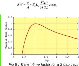
In a cavity optimised for a given β0 [ref. 13] the energy gain of an ion with a given q/A and a given veloci-ty βis:
The transit-time factor T(β)/T(β0) is represented on figure 8.
The superconducting linear accelerator will accel-erate ions from 1.67 A MeV to 100 A MeV, with a final magnetic rigidity of 4.43 Tm. An optimum scheme could be composed of 4 types of cavities with φs= 20°.
Superconducting Linear
accelerator (QWR)
Independently phased cavities
Ions A/q=3 1mA 295 MV
100 A MeV ions
protons :240MeV
deutons : 140 A MeV
Injector
Ions A/q=3
1mA
1.67 A MeV
Fig. 6 : Schematic layout of the linear accelerator €W q A E L T T a a s = • ( ) ( )cos ‚ ‚0 ƒ 0 0.2 0.4 0.6 0.8 1 1.2 0 0.5 1 1.5 2 2.5 3 T r a n s i t -T i m e F a c t o r €/€ 0Fig 8 : Transit-time factor for a 2 gap cavity
T
Ion source A/q=3 I=1 mA 60 kV RFQ-87.5MHz 5 MV E= 20 A keV E=1,67 A MeV (β=0.06)Fig. 7 : Schematic layout of the injector
Mhz
β
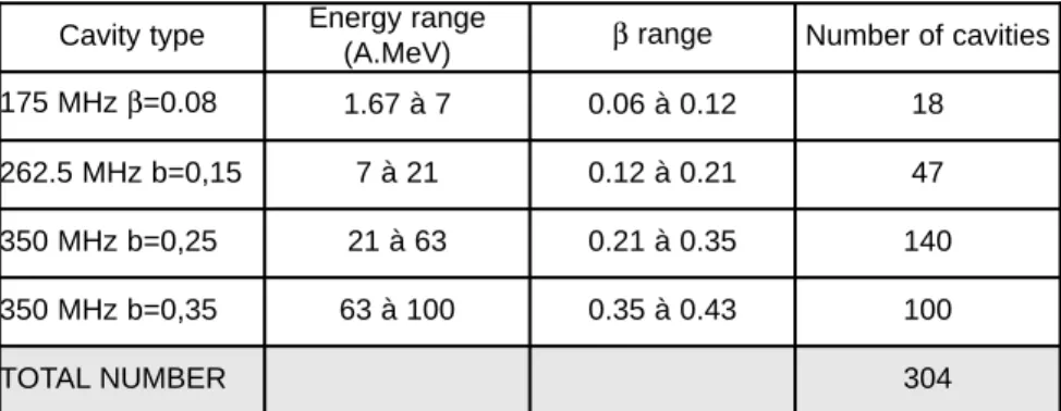
175 0.08 262.5 0.15 350 0.25 350 0.35 Page 5The National Laboratory of Legnaro has devel-oped and tested such cavities [ref. 14]. Accelerating fields around 6-7 MV/m have been obtained (with a cryogenic power of 7W per resonator), which corresponds approxi-mately to an acceleration of 1 MV per cavity. With these characteristics we obtain the structure of the accelerator as given in table 1.
Such a machine is very acceptant. With adapted injectors, A/q larger than 3 could also be accelerated in good conditions. The energy diagram of the supercon-ducting linear accelerator is presented in Fig.9.
Considering the “Legnaro ” scheme, with cryo-genic modules containing four cavities and one supercon-ducting solenoid for focusing, the present project results in a total of 76 modules with an approximate total length of 152 meters. The length might be reduced, if the number of solenoids can be decreased above an energy value to be defined . In this case, we could have modules containing 6 or even 8 cavities, instead of 4.
IV e) IMPLEMENTATIONS.
The whole accelerator requires a building with dimensions of approximately 100m by 25m, similar to the GANIL power supply building. The biological protections need to be calculated. By construction, the beam losses in the superconducting linear accelerator will have to be very low, thus heavy protections are mainly needed at beam dumps.
This building could be implemented in the North-West side of GANIL cyclotron building, with appropriate connections to the existing experimental areas
Fig.10 [ref : 22]. Here we show a possible implementation for an intermediate phase, corresponding to 40MeV deuterons. The full project could correpond to a prolonga-tion of this building. Implementaprolonga-tion must be optimised with repect to physics program.
Cavity type Energy range
(A.MeV) βrange Number of cavities 175 MHz β=0.08 1.67 à 7 0.06 à 0.12 18 262.5 MHz b=0,15 7 à 21 0.12 à 0.21 47 350 MHz b=0,25 21 à 63 0.21 à 0.35 140 350 MHz b=0,35 63 à 100 0.35 à 0.43 100
TOTAL NUMBER 304
Table.1 : Total number of cavities with the transit-time factor given by figure. 8
0 50 100 150 200 250 0 2 4 6 8 10 12
Maximum energy (A.MeV)
A/q
Fig 9 : Maximum energy versus A/q
10 m C IME unde rgr ound L IRA T N+ id en t. N + s p ec tro . s e pa ra to r R FQ LIN AC
IMPLEMENTATION
of the first stage (40 MeV deuterons)
IV f) PRELIMINARY COST ESTIMATION (without buildings, transport lines, and target station):
The cost estimates given below (table 2) are mostly based on Legnaro esti-mations made for a 100mA accelerator, corrected for the high RF power needed in the present project.
One possible capital investement plan is given in table 3 and 3bis. T0+4 cor-respond to the first, low energy phase dis-cussed below. The first beam produced at this stage with protons of 35 MeV, deuterons of 40MeV and A/q=3 of 14.5 A MeV could be delivered at T0+4.
EQUIPMENT COST ✁✄✂✆☎
SOURCE 0.76
RFQ 4.57
LINEAR ACCELERATOR
ONE MODULE <-> 4 MV (4 cavities+1 solenoid) 0,69
76 MODULES 52.44
ADDED COST FOR RF POWER FOR 10mA protons->35 MeV 3.05 ADDED COST FOR RF POWER FOR 1mA->100 A.MeV 6.86
CRYOGENIC PLANT 9.15
CONTROLS (5% total) 3.35
TOTAL with 20% margin 96.2
Table 2 Time in years T0 T0+4 T0+5 T0+6 T0+7 T0+8 T0+9 T0+10 T0+11 T0+12 Source + RFQ Cryogenic plant 3.05 3.05 accelerator modules 6,33 6,33 6,33 6,33 6,33 6,33 6,33 7,90 Controls 1.83
Total cost per year 6,33 9.38 6,33 8,16 9.38 6,33 6,33 7,90 Accumulated cost,no margin 19.8 26.13 35,51 41.84 50 59.38 65,71 72,04 79,94 q/A=1/3 energy (A.MeV) 14,5 24,5 36 45,6 55,8 65,5 76 86,5 99,6 Deuteron energy (A.MeV) 20,3 34,3 50 64,8 78,7 91,9 106,8 121,9 140,1
Proton energy (MeV) 34,6 58,7 96,4 111,5 135 157,4 193,6 209,8 241,3
Performances Time in years T0 T0+1 T0+2 T0+3 T0+4 RFQ 4.57 Source 0.38 0.38 Cryogenic plant 1.52 1.52 accelerator modules 3.81 3.05 3.05 Controls 0.76 0.76
Total cost per year 6.47 9.52 3.81
Accumulated cost,no
margin 6.47 15.99 19.8
Table 3 and 3 bis ✝✟✞ ✠☛✡☞✞✍✌ ✡✎✑✏ ✒✍✓ ☞✔✄✒✍✎✍☞✑✕✡✎✗✖✙✘✍✚☛✠☛✒✜✛✣✢✍✒✍✞✜✛
..
Expanded details concerning the first four years are given in lower part of the table.
Page 7
Total investement without building, beamline, target station ✤☛✥✟✦✧✩★✫✪✭✬✫✮✯✰✱✧✆✲✣✳✵✴✷✶☛✸✹✟✮✺
Investement for the first phase (see paragraph V) ✻✣✤✼✦✽✾★✫✪
Remark-1: An alternative intermediate solution has been considered, using IPHI [ref. 15], in order to accelerate pro-tons up to 35 MeV in a first step. This leads to an inter-✴✁
✂
✮✶✍✯☎✄✝✆✟✞✜✯✠✆✠✡✟✻☞☛✼✦✽✷★✗✪✍✌✣✮✺✎✞✜✯ ✑✶
✂
✆✠✡✼✻✜✤✟✦✽✷★✫✪ ✬✫✮✯✰✎✆✑✏✜✯✍✒✓✕✔✖✒✌ but the final cost of the whole accelerator would be ✮✺✝✄✑✸☛✶✎✞✎
✂✘✗✟✙
✶✠✚✟✚✆✸✆✟✛✑✮✴✷✶✍✯✢✜
✙
☛✟✦✣✠✤ ★✗✪ ✦
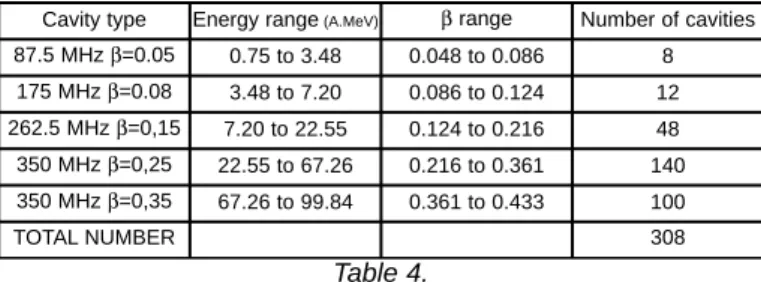
Remark-2: In the case where the proposed RFQ would present some technical difficulty to be realised, an alter-native solution for the accelerator would be to limit the RFQ exit energy to 0.75 A.MeV. (equivalent accelerating voltage: 2.25 MV instead of 5 MV, same frequency) In those conditions, a supplementary type of low βcavities would be necessary for the superconducting linear accel-erator, and the following scheme would be obtained (table 4).
The total cost of the superconducting cavities should not be affected much, and the RFQ study and con-struction would be simpler (and safer).
Cavity type Energy range(A.MeV) βrange Number of cavities 87.5 MHz β=0.05 0.75 to 3.48 0.048 to 0.086 8 175 MHz β=0.08 3.48 to 7.20 0.086 to 0.124 12 262.5 MHz β=0,15 7.20 to 22.55 0.124 to 0.216 48 350 MHz β=0,25 22.55 to 67.26 0.216 to 0.361 140 350 MHz β=0,35 67.26 to 99.84 0.361 to 0.433 100 TOTAL NUMBER 308 Page 8 Table 4.
IV g) Flexibility of a linear accelerator.
An independent superconducting cavity linac is flexible, and with a rather simple modification, it can be divided in 2 parts and be used simultaneously as a driver for A/q=3, and as a post-accelerator for larger A/q.
Example: driver for A/q=3 up to 36.5 A.MeV and post-accelerator for A/q=6 up to 24 MeV/A from the original linac defined by: Injector: RFQ with an energy exit =0.75 A.MeV
Cavity type Energy range(A.MeV) b range Number of cavities 175 MHz β=0.08 0.75 to 7.20 0.048 to 0.124 20 262.5 MHz β=0,15 7.20 to 22.55 0.124 to 0.216 48 350 MHz β=0,25 22.55 to 67.26 0.216 to 0.361 140 350 MHz β=0,35 67.26 to 99.84 0.361 to 0.433 100 TOTAL NUMBER 308 RFQ A/Q=3 0.75A.MeV injector A/q=6 0.75 A.MeV 164 cavities €=0.08 to €=0.25 154 cavities €=0.25 to €=0.35 10 cavities €=0.08 10 cavities €=0.15 A/q=3 36.4 A.MeV A/q=3 100 A.MeV A/q=6 24 A.MeV
By adding 20 cavities more (10 cavities β=0.08
and 10 cavities β=0.15) ,an appropriate injector for
Q/A=1/6 giving an energy of 0.75 A.MeV, and some
sup-plementary focusing elements, the following scheme can be obtained (see figure 10):
figure 10 : example of simulyaneous use as driver and post accelerator. Table 5.
V-A possible intermediate construction phase at an acceleration potential of 40MV
V a) General considerations on the production of RIB at low energy using a converter
As has been seen in the preceeding section, and as is inherent in the scheme of a linear accelerator, the construction can be divided into sections. After full con-struction, these sections may serve as beam outputs for different energy domains.
Here we want to consider an intermediate step at an acceleration potential of about 40MV. This corresponds to protons of 35MeV, or deuterons of 40MeV (see above, section IV). Quantitative evaluations of production rates of radioactive ions using a converter have been done in various reports [ref. 8, 16,17,18].
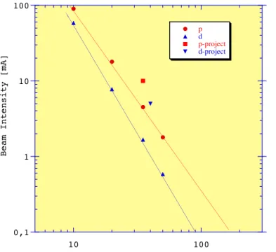
We illustrate the findings by the relation between the beam intensity necessary to produce 1013 fissions/s
and the incident energy, shown on figure 10. The convert-er considconvert-ered is Li, and the production geometry is the one with the use of UCx of [ref. 19]. A proton beam of 10mA and 350kW power, and deuteron beam of 5mA and 200kW at 40MeV, respectively are assumed. In the case of the use of IPHI as an intermediate solution, only pro-tons would be available, (eventually at higher intensity, IPHI being designed for 100mA of protons). At the low energy considered there is a strong quantitative difference between protons and deuterons as projectiles, and Li, Be and C as targets. This is considered in some more detail below.
V b) Protons or deuterons on Li and C converter
At low energy, one way to produce very high fis-sion yields with p or d beams is to use a converter in order to avoid high power dissipation in the target. One impor-tant feature is then the neutron production at forward angles, because these are the neutrons that induce the fission. We will limit our discussion here to the energy domain of 30-50MeV. Preceeding calculations were done for a Li target; Be can be shown to be more or less equiv-alent for neutron production, whereas C provides fewer neutrons at forward angles particulary for protons. Table 6 summarises these findings more quantitatively.
As can be seen from the table 5, there is no very strong target dependence of the neutron yield in the case of a d beam. In the case of protons, 12C gives
very low yields, and 13C should be used.
Two main methods may be considered for con-verters stopping high-power (<1MW) low-energy beams:
-A windowless liquid Li target. Such a tar-get has been constructed at Argonne,[ref. 20] for MW power dissipation. For much higher power, (i.e.10MW), such targets are part of the IFMIF proj-ect [ref. 7] . In our context of much lower power dis-sipation (350kW and 200kW for protons and deuterons respectively) costs and security con-straints would have to be evaluated.
-A fast rotating target. This target is very similar to that of the thin target production method involving heavy ions, as discussed in section II.a. It is shown that it should be possible to dissipate pow-ers up to 0.5MW in such type of targets. In the case of converters, C seems to be the most resilient material. 13C could be considered as target
materi-al, because only a limited quantity is necessary, of the order of 0.5kg in the geometry considered. If nat-ural C is used, this strongly favours the use of deuterons in this energy domain.
0,1 1 10 100 10 100 p d p-project d-project B e a m I n t e n s i t y [ m A ] Energy[MeV]
Figure 10: Beam intensity needed to induce 1013fissions/s as a
function of energy for protons and deuterons on a Li converter, in the geometry as described by [ref. 19]. Note that yields depend on the geometry and the quantity of fissile material. Here UCx (3kg) and a Li converter were asummed. The energy and the intensity of protons and deuterons are indicated for the first phase of the proj-ect .
Table 6: Calculated thick target neutron yield in units of neutrons/incident particle. The particle energy is 35MeV. The first column for each beam corresponds to the forward angle domain (0-30deg), the second to the yield over 4π solid angle. [ref. 15 and private communication].
Page 9 Protons deuterons 0-30deg 4π 0-30deg 4π 7Li 0.006 0.027 0.012 0.034 9Be 0.005 0.027 0.011 0.037 12C 0.0003 0.002 0.006 0.012 13C 0.003 0.019 0.008 0.027
These considerations show that there is no tech-nical impossibility concerning the high power target-con-verter, for protons as well as for deuterons. However, opti-misation of yield and cost-effectiveness may result in a preference for one of the beams.
With the intensities cited above and in the converter-production ion source geometry considered,
fission rates of the order of 1013 to 1014/s could be
reached with a heat production limited to the fission ener-gy, this is 0.3 to 3kW. In the converter-target geometry of the RTD project report SPIRAL II of M.G. Saint Laurent et al [Ref : 18], with a C converter and 360g of UCx mareri-al, 4.5mA of 40MeV deuterons would be necessary to pro-duce 1013 fissions/s, well within the range of projected
intensities.
Note that in the prospect of higher energies as future evolution, the range increases with E2. Thus
pro-duction luminosity will increase by roughly 1 to 2 orders of magnitude going from this intermediate stage to the final projected energy.
Vc) Direct target method
Fission induced directly by deuterons, without converter, may be advantageous, because it requires only small quantities of target material. With a the fission cross-section induced by protons or deuterons of 1.5mb [ref. 21] and the useful range of about 2g/cm2, this results
in 1x10¹³fissions/s for a beam of 0.33mA, corresponding
to 12kW. In this case, the target material mass could be as low as 10g. However 12kW of heat would have to be removed from the target-ion source.
Vd) Use for near Coulomb Barrier Physics.
This intermediate construction step with a 40MV acceleration potential, leads for A/q=3 to 14.5 A MeV, an energy sufficient for all near-barrier physics. This would allow users to do fusion-evaporation physics, like high spin physics. Remember that beam intensities of 1mA would be available with appropriate ion sources. This would permit research in the domain of low cross-section phenomena, such as formation of super heavy elements. The very high intensity would allow the production of rare fusion-evaporation products in thin targets. Coupled to with an appropriate separator, this could provide a mean of producing secondary beams for decay properties and reaction studies.
V e) Cost estimation and time schedule of the 40MV intermediate phase.
Table 7 gives an estimation of a time and cost schedule of this intermediate phase. T0is the time of decision of
con-struction and founding. The first beam can be expected 4 years later. The cost includes building and target ion source station, without margin.
Time in years T0 T0+1 T0+2 T0+3 T0+4 Total
Accelerator (see
Table 3bis) Technical study 6.47 9.52 3.81 19.8
Target/Source Technical study Technical study 3.04 3.04 6.08*
Bulding Technical study 3.35 3.35*
Beam lines Technical study 1.07 1.07 1.22 3.36*
Radioprotection Technical study Technical study 0.61 0.61 1.22*
Miscellaneous 0.3 0.3 0.3 0.9
Total cost per year 11.19 14.54 8.98
Accumulated
cost,no margin 0.3 11.49 26.03 35.01
Table 7 : Total cost estimates including building, target/source, beam lines, etc. * : Values from [ref. 21].
Page 10
VI. Conclusion.
We have shown that modern linear accelerator techniques together with high intensity ion sources deliv-ering high charge states, can provide an outstanding opportunity for GANIL to upgrade its research facilities in its domain of excellence. The linear accelerator proposed in this document would be able deliver beams of several hundreds of kilowatts from protons (6x10¹⁶ particles/s) up
to heavy ions with A=100 (2x10¹⁴ particles/s).
The final project would provide an increase of more than 2 orders of magnitude over the present primary beam intensities. For secondary beams, obtained by the thin target method (fragmentation), together with a mod-ern fragment separator, this would result in an increase of 3 to 4 orders of magnitude for fragmentation products. For secondary beams obtained by the thick target method (ISOL) or a combination of these two methods, the inten-sity would be increased more than two orders of magni-tude. Moreover, all techniques already develloped and presently applied at GANIL could be directly used in the new facility, provided the correct scaling would be done.
An intermediate stage of moderate size would provide the exploitation of the accelerator from the 4th year of construction. This initial stage would provide the following opportunities:
a) Production of fission products by protons or deuterons; three methods could be used, probably in a complementary way:
- Production of fission fragments by fast neutrons from a converter, decoupling the primary beam from the source of fission products. Up to about 1013 fissions/s
could be obtained with small quantities of UCx(360g), For bigger target volumes up to about 1014fission/s could be
expected.
- Production of fission fragments by direct bom-bardment of fissile material by protons or deuterons. This can produce about 1.1013fission/s for a 12kW power
dis-sipation, a number very similar to that for photo-fission. - Production of fission fragments by neutrons from a converter hitting a thin target in a He gas using IGISOL techniques. Very fast extraction would be possible for all chemical elements.
b) The physics domain from below the Coulomb barrier up to several times the barrier (14.5 A MeV) could be covered. The high intensity would give access to domains of very low cross-sections, such as the produc-tion of super heavy elements.
c) The very high intensity would allow the produc-tion of rare fusion-evaporaproduc-tion products in thin targets. Coupled to an appropriate separator, this could provide a mean of producing secondary beams for decay properties and reaction studies.
The realisation of such a project would provide a versatile instrument covering a broad range of physics in a large energy range. It offers the possibility of a con-struction in complementary parts. The overall cost of such project is naturally quite high. It will have to be integrated in the European and International context.
Acknowledgment: The authors thanks for fruitful discus-sions with A.Chabert (GANIL), and J.M.Lagniel (SEA-CEA)
I- Comparative study between a high energy proton and a light and heavy ion driver for Isol beams
or this comparative study, data from the NSAC task force on Radioactive Ion Beam are available on the web site of the task force [22] and has been collected by Paul Schmor (Triumf) from different sources/specialists over the world. In this document are considered thick target method (ISOL) yield using the following accelerators:
1- 1 GeV proton accelerator with 100 µA of beam intensi-ty, corresponding to a maximum of 100kW beam power, called HE proton.
2- 100 A MeV light and heavy ion accelerator with maxi-mum intensity corresponding to the same 100kW of beam power, called Heavy ion.
The maximum intensity on different targets has been limited, in some cases, according to present knowl-edge on chemical properties, heat resistance and the maximum expected heavy ion intensities within the next 5 years. The final RIB intensities of a hypothetical final proj-ect can be taken dirproj-ectly from this table, multiplying the RIB yield by the hypothetical maximum intensity available in the future. In the case of heavy ions, the present pro-posed facility would be able to accelerate up to 300 kW, instead of 100kW. Therefore, the final intensities of the proposed facility will be a factor 3 higher than the num-bers we quote from the reference [23].
Five cases can be taken as typical examples of these tables. The final yields take into account diffusion, effusion and ionisation to 1+charge state.
1- Production of 11Li:
With 1GeV protons on UC target of 1000cm3volume, the
production yield is 3.7x10⁶pps.
With 18O on a two step target (Li + C), of 4 cm3 volume,
the production yield would be of 1.4x10⁸pps.
The heavy ion driver has an advantage of a factor 30 for this short lived isotope.
2- Production of 37K:
With 1GeV protons on CaO target with 1000 cm3 volume, the production yield would be of 2.4x10¹²pps.
With 0.2GeV protons on CaO target with 900cm3volume,
the production yield would be of 1.1x10¹³pps.
The heavy ion driver used for the acceleration of protons has an advantage of a factor 4.
3- Production of 52Ni:
With 1GeV protons on ZrO2target with 1000cm3volume,
the production yield would be of 8.3x10⁻²pps.
With 58Ni on a two step target + gas catcher (Li + He), the
production yield would be of 5.4x10³ pps. The gain in
favour of a heavy ion driver (a factor 104) is clear for this
short lived isotope, mainly due to the fast extraction in the gas catcher. An efficiency of 6% was assumed for the gas cather.
4- Production of 132Sn:
With 1GeV protons on UC target with 820cm3volume, the
production yield would be of 2.2x10¹⁰ pps. With 0.2GeV
deuterons on a W converter followed by a UC target of 180cm3volume, the production yield would be of 1.4x10¹¹
pps. The heavy ion driver used for the acceleration of deuterons has an advantage of a factor 6.
5- Production of 227Fr:
With 1GeV protons on ThC target with 820cm3 volume,
the production yield would be of 7.6x10¹⁰ pps. With
0.44GeV 3He on ThC target with 360cm3volume, the
pro-duction yield would be of 7.2x10¹⁰ pps. The yields are
similar in this case.
A more general analysis of this table leads to the following qualitative conclusions :
HE protons are favoured in the region close to the stability and heavy ions far from stability. This is mainly due to the use of different techniques. With heavy ions the problems of beam power deposition and the release out of the target can be de-coupled, minimising losses for nuclei of short lifetimes. For the HE protons, the larger range results in higher in-target production of radioactive nuclei, providing higher final yields for long lifetimes.
Heavy ions are clearly advantageous if one takes into account the fact that the heavy ion driver can be used not only for thick target (ISOL), but also for thin target (In-Flight) method. The thin target method allows to have energetic RIB in the energy range of 20 to 100 A MeV without re-acceleration. The method is extremely fast (less than 1 µs), allowing to produce beams very far from stability, with very short lifetimes. In addition, there is no chemical selectivity.
II - Comparison with the project of GSI.
The projected maximum primary beam intensity of GSI is 1.0 x10¹²pps from protons to Uranium at 1.0A
GeV.
F
Page 12
Supposing a spectrometer with large angular acceptance, and a given momentum acceptance, the yield increases approximatively proportional to the range. This would give a factor 40 higher yield per incident parti-cle. In the solution proposed in the present document, the primary beam intensity is of the order of 1015pps for 18O
and 3x10¹⁴for 40Ar. The final RIB intensity of the present
proposed facility is more than one order of magnitude higher than the future GSI project in the mass region A<100.Moreover, the energy region covered by both accelerators is different.
The GSI project is not yet funded.
III - Comparison with RIKEN factory.
The primary beam intensity of the RIKEN RI beam factory is, at least, one order of magnitude smaller than the one of the present proposed facility. No thick tar-get production method is proposed at RIKEN, therefore, no low energy high quality beam would be available. The first phase of the RIKEN RI beam factory is under con-struction.
IV - Comparison with RIA.
Beam intensities proposed for RIA are similar to those in the present document. The factor 4 higher ener-gy in the RIA project is compensated to a good part by the factor 3 higher beam intensity in the present project. The high energy U-like fragmentation, which could be covered in the RIA approach, would not be accessed in the pres-ent project. The projectile fragmpres-entation of very heavy ions would be covered, in Europe, by the GSI new project for the thin target method.
RIA is not yet funded.
Page 13 References :
1 : Long term plans in the study of atomic nuclei.
Hors série nouvelles du GANIL
2. http://www.ganil.fr/eurisol
3 : http://www.nscl.msu.edu
4 : adapted from R. Bennett and A.C.C. Villari, FINA
report (2001)
5 : R3B research project, see e.g the report by A. de
Vimes
6 : http://www.lanl.gov
7: http://insdell.tokai.jaeri.go.jp/IFMIFHOME/
ifmif_home_e.html
8 : C.Lau, Thesis, IPN Orsay, Note IPNO T000-08
9 : L. Maunoury et al. , preprint Ganil (Ganil S 01 02)
10 : 12th ECRIS conference (1995)
11 : C.Barué, private communication.
12 : Discussion with J-M Lagniel et B.Aune from
SEA-DAPNIA-CEA
13 : Rapport GANIL R 92 04- A.Chabert
14 : A.Facco Presentation at Eurisol meeting held in
Legnaro on 27th February-
15 : http://cern.web.cern.ch/CERN/Divisions/PS/
Linac96/Proceedings/Monday/MOP58/ Paper.html
16 : D.Ridikas Thesis, Caen 1999 GANIL – T 99 04
17 : D.Ridikas and W.Mittig, GANIL P 98 22.
18 : M.G.Saint Laurent, report on the RTD Spiral2,
2001
19 : D.Ridikas, A.C.C.Villari, and W.Mittig, report to the scientific council of GANIL, 2000
20 : http://srfsrv.jlab.org/isol/ ISOLTaskForceReport.pdf
21 : J.P.C.Stevenson et al.,Phys.Rev.111(1958)886
22 : F.Loyer (private communication)
![Figure 1. All potential RIB production methods with a heavy ion driver [ref. 4]. GANIL already developed and routinely uses most of the branches shown.](https://thumb-eu.123doks.com/thumbv2/123doknet/12687475.354848/4.892.372.792.282.677/figure-potential-production-methods-driver-developed-routinely-branches.webp)

![Fig. 5 : Evolution of the intensity of Ar during the last two decades [ref. 10]. The different lines indicate an extrapolation.](https://thumb-eu.123doks.com/thumbv2/123doknet/12687475.354848/6.892.71.434.262.558/fig-evolution-intensity-decades-different-lines-indicate-extrapolation.webp)