22. Atomic Resonance and Scattering
Academic and Research StaffProf. D. Kleppner, Prof. D.E. Pritchard, Dr. J. Derouard, Dr. G. Lafyatis
Graduate Students
V. Bagnato, P.P. Chang, E. Cornell, T. Ducas, B. Flanagan, T. Gentile, E. Hilfer, B. Hughey, C.-H. lu, M. Kamal, M. Kash, J. Landry, M. Lee, P. Magill, P. Martin, A. Miklich, W. Moskowitz, B. Oldaker, S. Osofsky, S. Paine, E. Raab, R. Singerman, B. Stewart, S. Vianna, R. Weiskoff, G. Welch
22.1 Basic Atomic Physics
National Science Foundation (PHY83-062 73)Michael M. Kash, George R. Welch, Chun-Ho lu, Daniel Kleppner
22.1.1 Rydber Atoms in a Magnetic Field
We have produced Rydberg atoms in a lithium atomic beam using cw dye lasers, and developed the technology for detecting these atoms with electric field ionization. These advances have brought us close to the point where we can start carrying out high resolution measurements on
highly excited atoms in a strong magnetic field by cw laser spectroscopy.
photon counting signal
loser froquency [1000 MHz full scale]
Figure 22-1: Cascade fluorescence (2p -+ 2s) rate versus ring laser frequency. The two peaks reflect the hyperfine structure of
the 32 1/2 and 2 1/2 1/2S 1/2states of lithium 7.
Understanding the diamagnetic spectrum of an atom with a single valence electron presents a
RLE P.R. No. 128 1. 25 S1.00 U Co S75 x ato .s L .50 , a .25 0 145
Atomic Resonance and Scattering
formidable challenge to theory and experiment.' The classical and quantum mechanical equations of motion are easily constructed, but in spite of the simplicity of the problem the solutions are elusive and our understanding is far from complete. Numerical techniques have been applied to both the classical2 and quantum3 dynamics, but the results possess features which are difficult to interpret. Construction of an approximate constant of motion is a promising method for predicting the spectrum of a hydrogen atom in a uniform magnetic field.4 Our primary task is to measure the level anticrossing sizes and linewidths in the diamagnetic spectrum of atomic lithium, for these can establish the credibility of such an operator.5
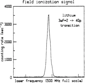
The excitation of lithium Rydberg atoms is performed with a two-step, three-photon process. The first step is a two-photon transition from the 2s state to the 3s state. This step is detected by observing the cascade fluorescence (3s --, 2p, 2p -- 2s) through a fiber optic bundle with a sensitive photomultiplier tube. The transition is excited by 735 nm light from a Coherent ring dye laser. The 2p -+ 2s fluorescence as a function of ring laser frequency is shown in Fig. 22-1. The ring laser is stabilized against slow drift by locking to the larger peak's center. The second step is a one-photon transition from the 3s state to the np state. This is observed by counting electrons which are produced in ionizing the excited atoms as they move from the interaction volume into a region of static electric field, 5-10 kV/cm. The electrons are counted with a surface barrier diode. Standard devices such as electron multiplier tubes, channeltron multiplers, or micro-channel plates do not operate in a strong magnetic field, greater than 1 Tesla. Figure 22-2 illustrates the electron counting rate versus linear laser frequency, near the 3s --, 40p transition. The FWHM linewidth of 28 MHz represents an important advance in Rydberg atom spectroscopy.
field ionization signal
4000 lithium 3GF-2 -> 40p -O " transition +U S2000 4, 1000ooo
loser frequency [500 MHz full scale]
Figure 22-2: Electric field ionization rate versus linear laser frequency. The HWHM linewidth is 28 MHz.
To minimize the electric field in the atom's rest frame, the atomic beam of lithium is parallel to the axis of a solenoid superconductive magnet. The interaction region consists of an aluminum
cylinder whose axis is parallel to the atomic beam. The cylinder also contains prisms to deflect
the lasers so that the laser and atomic beams intersect at right angles, to minimize Doppler broadening. The interaction region combines efficient collection of cascade fluorescence with good geometric rejection of scattered laser light.
We expect to energize the magnet in the near future.
References
1. J.C. Gay, "High-Magnetic Field Atomic Physics," in H.J. Beyer, H. Kleinpoppen (Eds.), Progress in Atomic Spectroscopy, (Plenum Press 1984).
2. J. Delos, S.K. Knudson, and D.W. Nord, Phys. Rev. A 30, 1208 (1984).
3. J.C. Castro, M.L. Zimmerman, R.G. Hulet, D. Kleppner, and R.R. Freeman, Phys. Rev. Lett 45,
1780 (1980).
4. D.R. Henick, Phys. Rev. A. 26, 323 (1982).
5. M.L. Zimmerman, M.M. Kash, and G.R. Welsh, J. de Phys. Col. C2 43, 113 (1982).
22.2 Rydberg Atoms and Radiation
Joint Services Electronics Program (DAAL03-86-K-0002) National Science Foundation (PHY84-11483)U.S. Navy-Office of Naval Research (Grant N000 14-79-C-0183)
Barbara Hughey, Thomas Gentile, Eric Hilfer, Sandra Vianna, Randall Hulet, Daniel Kleppner
22.2.1 Inhibited Spontaneous Emission
We have achieved our initial goal in the study of basic radiative processes using Rydberg atoms - the observation of inhibited spontaneous emission.' An experiment has been carried out demonstrating that spontaneous emission can be effectively turned off.2
The underlying principle is that spontaneous emission results from the radiative coupling between matter and a continuum of vacuum states. However, the assumptions underlying the conventional calculation of the density of modes in free space are not always valid. In particular, cavities can dramatically effect spontaneous emission. Such effects are difficult to observe in the optical regime because of the problem of making good fundamental mode cavities at short wavelengths. Excellent cavities can be made at microwave wavelengths, but spontaneous emission is normally too slow to observe in this regime. For Rydberg atoms (highly excited atoms), however, spontaneous emission is enhanced by a factor of n4 where n is the principle quantum number, allowing such effects to be studied.
The experiment involved measuring the natural lifetime (i.e., the inverse of the spontaneous emission rate) for the transition n = 23 -+ n = 22 in cesium. "Circular" Rydberg states were employed.3 These states have the maximum possible angular momentum (m = / = n-1); their value
lies in possessing only a single dipole radiation channel. The radiative lifetime was measured by
RLE P.R. No. 128 147
Atomic Resonance and Scattering
time-of-flight spectroscopy.
Atoms were excited to the Rydberg state by light from pulsed dye lasers and by multiphoton microwave absorption. They then drifted approximately 15 cm to a time-resolved detector which was sensitive only to the n = 22 atoms. The drift time was chosen to be close to the free space radiative lifetime. Thus, the time-of-flight spectrum was the product of the probability density for the Maxwell-Boltzmann velocity distribution of the atomic beam and the exponential decay curve for spontaneous emission. To assure accuracy of the method, the free space lifetime was compared to the theoretical result and was found to agree within the experimental resolution, approximately 2%.
Next, the drift space was modified by the introduction of two parallel conducting plates separated by the distance d = X/2. The plates behav.ed effectively as a waveguide at cutoff. It can be shown that in this situation the decay rate switches abruptly from zero to a value slightly greater than the free space value as the cutoff separation is exceeded. In the experiment the plate separation was kept fixed and the wavelength was slightly varied by the Stark effect in an applied electric field.
Figure 22-3 shows the experimental time-of-flight curves on either side of cutoff. The area under the curves is proportional to the total number of atoms that reached the detector. The most conspicuous effect of inhibited spontaneous emission is the great increase in area. However, the shape of the curve also contains information about the lifetime. In the inhibited regime the lifetime was determined to be at least twenty times larger than the free space value.
I-0 200 400 600 800 000 1200 400 1600 TIME (M S)
Figure 22-3: Inhibited spantaneous emission. Time-of-flight data for inhibited emission (X/2d > 1, curve B) and enhanced
emission (A\/2d < 1, curve A).
Inhibited spontaneous emission offers the possibility of increasing the resolution of spectroscopic measurements beyond the limit set by the natural lifetime. The experiment has
also achieved significantly longer time-of-flight times than previously possible with Rydberg atoms, providing a useful technological advance toward high resolution millimeter wave spectroscopy.
22.2.2 Rydberg Atoms in Cavities
Thomas Gentile, Barbara Hughey, Daniel Kleppner
We are carrying out a study of single Rydberg atoms radiating into a single mode of the radiation field at a temperature which is effectively zero. Work is in progress on designing the beam and preparing the cavity.
References
1. D. Kleppner, Phys. Rev. Lett. 47, 233 (1981).
2. R.G. Hulet, E. Hilfer, D. Kleppner, Phys. Rev. Lett. 55, 2137 (1985). 3. R.G. Hulet and D. Kleppner, Phys. Rev. Lett. 51, 1430 (1983).
22.3 High Precision Mass Measurement on Single
Ions
Using
Cyclotron Resonance
Joint Services Electronics Program (Contract DAAG29-83-K-0003) National Science Foundation (Grant PHY83-07172-A01)
Eric A. Cornell, Robert W. Flanagan, Jr., Phillip L. Gould, Gregory P. Lafyatis, Peter J. Martin, David E. Pritchard, Robert M. Weisskoff
We have begun an experiment in which ion cyclotron resonance will be used to compare the masses of individual atomic and molecular ions with a precision approaching 10-12. Our main scientific objectives and motivations are: improved measurements of Avogadro's number, recalibration of the x-ray wavelength standard (by "weighing" y-rays), limitations on the neutrino rest mass, more precise determination of neutron mass and deuteron binding energy, and weighing chemical bonds and ionic binding energies. Ultimately we expect our technique to cause a small revolution in the field of mass spectrometry where the single ion sensitivity will be as revolutionary as the orders of magnitude improvement in precision.
Our experimental research is directed toward developing techniques to trap, manipulate and store individual molecular ions similar to ones developed at the University of Washington for trapping and studying single electrons.1'2,3 The key to this is the development of a superconducting quantum interference detector (SQUID) to detect the ~10- 14 amp current induced in the trap electrodes by each oscillating ion. The most gratifying progress made this past year was therefore the successful operation of our superconducting coupling circuit, feedback electronics, SQUID, and computer data taking system and the recording of the 4 Kelvin
RLE P.R. No. 128 149
Atomic Resonance and Scattering
z
i-OC0
0
1000
FREQUENCY - 201,150 Hz
Figure 22-4: FFT of current density vs. frequency for 4 seconds of data collection.
thermal noise in the coupling circuit shown in Fig. 22-4.
The second major advance of the past year was completion of the apparatus. A custom NMR magnet with a measured homogeneity of 1.4 x 10⁻⁸ over 1 cm has been installed. A precision
machined Penning trap and its related circuitry have been assembled in our ultra high vacuum cryogenic envelope which has been lowered into the custom designed cryogenic bore tube of the magnet. The SQUID system has been operated with the experiment "on," and a search for trapped ions will commence when modifications to our ion injection system are complete.
References
1. R.S. VanDyck, Jr., P.B. Schwinberg, H.G. Dehmelt, Atomic Phys. 9, 53 (1984).
2. R.S. VanDyck, Jr., P.B. Schwinberg, and HI.G. Dehmelt, Atomic Phys. 17, 340 (1981); also R.S. VanDyck, Jr., and P.B. Schwinberg, Phys. Rev. Lett. 47, 395 (1981).
3. L.S. Brown and G. Gabrielse, Rev. Mod. Phys., to be published. 4. W. Thompson and S. Hanrahan, J. Vac. Sci. Technol. 14, 643 (1972).
22.4 Trapping of Neutral Atoms
U.S. Navy - Office of Naval Research (Grant N000 14-83-K-0695)
Vanderlei Bagnato, Gregory P. Lafyatis, Sam Osofsky, Eric Raab, Riyad Ahmad-Bitar, David E. Pritchard
We are building an apparatus to slow and trap neutral atoms. We expect the confinement time to be days, and we hope to be able to cool the atoms to the order of 10-7 Kelvin using a variety of laser-based techniques which we have proposed.' In addition to the interesting scientific and technical challenges involved in the trapping and cooling, we hope to open several new lines of
RLE P.R. No. 128
SIMULATED
ION PEAK
investigation with these cooled atoms. These atoms constitute a good system for studying collective phenomena such as Bose condensation, low energy collisions such as between Na-Na and Na-Na , and coherent optical effects (the deBroglie wavelength can exceed the optical wavelength). The trapped atoms offer opportunities for performing ultra-high resolution spectroscopy and are extremely promising candidates for a new generation of frequency standards. 16 V, 0 8PART - PART I SPOSITION (cm) 0 75 150 225 300
Na- SOURCE ATOMIC BEAM LASER BEAM
Figure 22-5: The longitudinal magnetic field and the atomic and laser beams configuration. Atoms whose energy increases with
increasing magnetic field can be trapped near 225 cm.
During 1985 we designed and began construction of a superconducting magnetic field (see Fig. 22-5) to decelerate and trap Na atoms. The key idea is to trap atoms in those quantum states whose electron spin is up - these experience a force toward regions with weak magnetic field (cf. a Stern Gerlach magnet). Our trap should have a depth of -1 Kelvin, necessitating a scheme for slowing Na atoms from a hot oven. This is accomplished by directing a resonant laser against the propagation direction of the atomic beam such that the absorption of photons reduces the momentum of the atoms. To compensate for the changing Doppler shift of the slowing atoms, we use a parabolic magnetic field (part 1 of Fig. 22-5) which keeps the decelerating atoms resonant with the laser, a technique pioneered by Bill Phillips et al. at N.B.S.2
References
1. D.E. Pritchard, Phys. Rev. Lett. 51, 1336 (1983); also ICPEAC talk 1985. 2. J.V. Prodan, W.D. Phillips, and H.J. Metcalf, Phys. Rev. Lett. 49, 1149 (1982).
22.5
Experimental Study of Forces on Atoms Due to Light
National Science Foundation (Grant PHY83-07172-A01)
Phillip L. Gould, George A. Ruff, Peter J. Martin, Katherine Schwarz, Richard E. Stoner, David E. Pritchard
Atomic Resonance and Scattering
We are investigating the radiative forces experienced by an atom in a standing wave laser field. These forces provide a new way to study the fundamental interaction between atoms and radiation, and also have important applications in the slowing, cooling, and trapping of neutral atoms using light.
In the absence of spontaneous decay, the radiative interaction can be viewed as the
"diffraction" of the atomic deBroglie waves by the intensity "grating" of the standing wave. Since the intensity has a period of X/2, momentum is transferred in units of h/(X/2) = 2hk (the reciprocal lattice vector), i.e., twice the momentum of a single photon. This is the near-resonant Kapitza-Dirac effect.1 11
>_
.05
-
1
I
8
/ \- \ f i-8
-4
0
4
8
Ap/fk
-20 -16 -12 -8 -4 0 4 8 12 16 20 Ap/hkFigure 22-6: (a) Diffractive Regime. (b) Diffusive Regime
The momentum transfer can also be viewed in terms of a classical force (the induced force)
which arises from the interaction of the induced electric dipole moment with the gradient of the standing-wave electric field. Spontaneous emission leads to fluctuations in this induced force and results in a diffusion of the atomic momentum,2 i.e., a random walk in momentum space.
By deflecting a highly collimated (0.7 hk FWHM resolution), state-selected (90% of atoms in desired state), and velocity-selected (11% FWHM) atomic sodium beam with a well characterized standing-wave, we have been able to make quantitative measurements of atomic diffraction3 and momentum diffusion for the first time.
In Fig. 22-6(a) we present an example of atomic beam diffraction (solid line) and the corresponding theoretical fit (dashed line). Diffraction in multiples of 2hk is very pronounced and the agreement with theory is good. Figure 22-6(b) is an example of momentum diffusion where
-5 spontaneous decays have occurred during the interaction. Here the diffraction structure is seen to wash out due to the random direction of the spontaneously emitted photons. Here, the
agreement between the theory' (dashed line) and the data (solid line) is fair.
References
1. P.L. Kapitza and P.A.M. Dirace, Proc. Cambridge Phil. Soc. 29, 297 (1933). 2. R.J. Cook, Phys. Rev. Lett. 44, 976 (1980).
3. P.L. Gould, G.A. Ruff, and D.E. Pritchard, Phys. Rev. Lett., accepted for publication.
4. C. Tanguy, S. Reynaud, M. Matsuoka, and C. Cohen-Tannoudji, Opt. Commun. 44, 249 (1983).
22.6 State Selected Atom-Molecule Collisions
National Science Foundation (Grant CHE84-21392)Peter Magill, Brian Stewart, Minae Lee, David Pritchard
In the past year we have made great advances in our understanding of vibration-rotation (V-R) transfer in diatomic molecular collisions. Recent experimental measurements1,2 mad.e in our lab
of
Li (',ii) + X -+ Li (jv.j) + X
(X = various rare gases) have shown a very specific resonant exchange between vibration and rotation with a very large cross section (see Fig. 22-7).
The change in the rotational level at the peak is less than that given by complete conversion of vibrational energy into rotation and the process is therefore termed quasi-resonant. The conditions under which this transfer is observed are high initial rotation (Fig. 22-8) and low collision velocity (Fig. 22-9).
RLE P.R. No. 128 153
Atomic Resonance and Scattering y, U-Figure 22-7:
3x10
E
o-) 0CC
Rate constant k 4, 44 - v = +Av
I.i-Xe, Av = -2,-1,'+ 1, -2 collisi6ns!
Li
-Xe
V
i=4 v
=-I
Sj
=14
x
ji
=28
*
Ji=44
XXXXX . xxxxx e*AAA XXXXx
i)
12
24
36
48
60
Figure 22-8: Rate constant k 44 collisions.
f
S4,j
4,} -. Vy=3J1 vs. for *f I.i22- XOur recent understanding is the result of studies of these collisions using classical trajectories3'4 calculated using an efficient computer program. One of the innovations in this program is the use of action-angle variables for the internal modes of the molecule throughout the trajectory. This enables us to monitor the observables v and i during the entire collision and to study the effects of all details of the dynamics on them. Another innovation is storing the results of each trajectory (e.g., vf and j,) as continuous (i.e., classical) variables instead of binning them to allowed quantum values as is conventional. This gives us great insight into the dynamics of these collisions and allows us to understand many features of the collisions which would be missed using a computational procedure which determines only the final result.
For example, Fig. 22-10 displays the results of 20,000 trajectories all with the same initial vibration (vi), rotation (ji), and relative velocity (v,), but randomly chosen phase of rotation and
RLE P.R. No. 128
VS. j/ for
e,j = 14, 28,
c< o.b b 4.0 3.0 2.0 1.0 40 50
Jf
Figure 22-9: Cross sections a = 9 j = 42 -4 .= 8 ,/vs. /.for L.i- Xc at
4 values of relative velocity.
1 5 .. 25 -120- Li - Ne -15 --20 =42 25 -5 -4 -3 -2 - I 2 3 4
Figure 22-10: Results of trajectory calculations of J.i -Ne collisions plotted with one dot at the outcome of each trajectory
(Aj vs. Av plane) for ji = 42, ,v= .97.
vibration, impact parameter, and orientation of the rotation axis. A single dot was then plotted at the outcome (i j , .) for each trajectory.
By comparing Figs. 22-10 and 22-11 one can readily see the effects of increasing the initial rotation: a very strong linear correlation develops between J. and v Additionally the cross section (which is proportional to the density of dots) for substantial changes in v increases dramatically. These are the same effects seen in the experimental measurements (Figs. 22-4 and 22-5). Now comparing Figs. 22-8 and 22-9 demonstrates the effects of lowering the relative velocity of the collision partners: a strengthening of the correlation of .with 1jfand an increase in
RLE P.R. No. 128 155
Atomic Resonance and Scattering 25-20 15 I0- 5- 0--5 -10- -15--20 -2515 Figure 22-11 -4 -3 -2 -1 0 I 2
:
Results of trajectory calculations plotted with one clot at the outcome vs. Av plane) for .i = 60, vr = .97.3 4
of .i, - Ne collisions of each trajectory (Aj
the cross section for changing v. 22-12.
Against this parallels the experimental results shown in Fig.
-5 -10--15'
-20--25
-5 -4 -3 -2 -1 Av 0 I 2 3 4
Figure 22-12: Results of trajectory calculations of l.i2-Ne collisions plotted with one dot at the outcome of each trajectory (Aj vs. A v plane) for i = 60,v = .5.
By further study we have found that all of this behavior is due to purely classical resonances which arise when the vibration frequency w is an integral multiple of the effective rotation frequency WI,. Near these resonances the cross section is greatly enhanced for changing v when the colliding atom remains near the molecule for at least a few rotations (i.e., at low relative velocity). All of our highest ji measurements have coincidentally been made quite near one of these resonances for / i(A 'g) at ii = 42. However, our calculations make a strong prediction that the cross section for changing v should decrease at j;= 51 for low velocity collisions. Therefore we plan to make additional measurements at this high initial rotation.
References
1. K.L. Saenger, N. Smith, S.L. Dexheimer, C. Engelke, and D.E. Pritchard, J. Chem. Phys. 79,
4076 (1983).
2. T.P. Scott, Ph.D. Thesis, Physics Department, M.I.T., January 1985. 3. N. Smith, Ph.D. Thesis, Physics Department, M.I.T., January 1985. 4. N. Smith, J. Chem. Phys., accepted for publication.
RLE P.R. No. 128 157
Plasma Dynamics