Publisher’s version / Version de l'éditeur:
Vous avez des questions? Nous pouvons vous aider. Pour communiquer directement avec un auteur, consultez la première page de la revue dans laquelle son article a été publié afin de trouver ses coordonnées. Si vous n’arrivez pas à les repérer, communiquez avec nous à [email protected].
Questions? Contact the NRC Publications Archive team at
[email protected]. If you wish to email the authors directly, please see the first page of the publication for their contact information.
https://publications-cnrc.canada.ca/fra/droits
L’accès à ce site Web et l’utilisation de son contenu sont assujettis aux conditions présentées dans le site LISEZ CES CONDITIONS ATTENTIVEMENT AVANT D’UTILISER CE SITE WEB.
1st International Syposium on Laser Ultrasonics: Science, Technology and Applications [Proceedings], pp. 1-6, 2008
READ THESE TERMS AND CONDITIONS CAREFULLY BEFORE USING THIS WEBSITE.
https://nrc-publications.canada.ca/eng/copyright
NRC Publications Archive Record / Notice des Archives des publications du CNRC : https://nrc-publications.canada.ca/eng/view/object/?id=24911933-6843-4673-9955-1eccbd8f801e https://publications-cnrc.canada.ca/fra/voir/objet/?id=24911933-6843-4673-9955-1eccbd8f801e
NRC Publications Archive
Archives des publications du CNRC
This publication could be one of several versions: author’s original, accepted manuscript or the publisher’s version. / La version de cette publication peut être l’une des suivantes : la version prépublication de l’auteur, la version acceptée du manuscrit ou la version de l’éditeur.
Access and use of this website and the material on it are subject to the Terms and Conditions set forth at
Detection of Skin Disbond in Honeycombs and Coating Detachment by Laser Tapping Technique
Blouin, Alain; Campagne, Benjamin; Néron, Christian; Monchalin, Jean-Pierre
Detection of Skin Disbond in Honeycombs and Coating Detachment by
Laser Tapping Technique
Alain BLOUIN, Benjamin CAMPAGNE *, Christian NERON, Jean-Pierre MONCHALIN
Industrial Materials Institute, National Research Council Canada, 75 de Mortagne Blvd, Boucherville, Québec, Canada, J4B 6Y4
Phone: (450) 641-5112, Fax (450) 641-5106; e-mail: [email protected]
* Present Address: EADS Innovation Works,
Non Destructive Investigations & Structural Health Monitoring 12 rue Pasteur, BP 76, 92152 Suresnes Cedex, France
Abstract
Many engineering structures are made of composite materials and include, for example, a protective coating or a bonded layer. We have developed a novel technique, similar to laser-ultrasonics that allows the detection of disbonds between the coating or the bonded layer and the substrate. The technique is also applicable to the detection of unbonds in honeycomb structures. The technique is based on the thermoelastic excitation by a laser pulse of the top layer or top skin which is driven into vibration if it is detached from the substrate underneath. This vibration is then detected by a second laser coupled to a photorefractive interferometer. This detection laser is a single frequency, very stable laser, which delivers optical pulses of a few hundred of microseconds, long enough to capture the low frequency membrane vibrations of the disbonded layers. Photorefractive interferometers allow processing these low frequencies while keeping the system insensitive to ambient vibrations. One of the most promising applications is the in-service inspection of aerospace structures for the detection of core unbonds in honeycombs or near surface delaminations.
Keywords: Laser-ultrasonics, laser-ultrasound, laser-based ultrasound, disbonds, coatings, honeycomb
structures.
1. Introduction
Honeycomb-structured materials allow reducing weight while keeping a very high stiffness, and are widely used in the aeronautic industry. Detachments between the skin and the ribs of the honeycomb weaken considerably the structure. Therefore, probing honeycomb-structured components to find any detachment is highly critical to assess the quality for either newly produced parts and for parts damaged during service. Coatings are another example of structured or layered materials for which adhesion assessment is critical. Coatings are widely used on industrial material surfaces for protection against wear, oxidation and corrosion, or as thermal barriers. Voids or detachments at the coating-substrate interface result into a fragile coating that could peel off, leaving the substrate unprotected and subjected to severe heat load, erosion, oxidation or corrosion.
This paper reports on an approach based on the transient and local heating of the material surface by a pulsed laser followed by an interferometric interrogation of the surface deformation by another laser [1]. The method is made practical by using a two-wave mixing photorefractive interferometer [2] or a similar detection device such as a photo-EMF-based interferometer [3]. The two main features of these interferometers
relevant for this application are their large etendues or their ability to process many optical speckles simultaneously, and their sensitivity to acoustic frequencies in the range of 1 kHz to 1 MHz. On honeycomb, the proposed technique could also exploit the ultrasonic waves that are generated to get a more thorough and reliable inspection by allowing one to distinguish disbonds within the skin from the detachment of the skin itself. The principle of the technique that could be called laser-acoustics or laser tapping is described next, followed by examples of application to honeycomb structures and coatings.
2. Principle of Laser Tapping
The principle of laser tapping is shown in Figure 1. A laser pulse is absorbed at the material surface and produces a transient and local surface heating. When the laser heating is not uniform and concentrated over an area smaller than the size of the detached zone, localized thermal stresses are produced that cause a strong lifting and bending effect. The disbonded layer or skin can then be set into vibration like a membrane [1]. The modes of the vibration induced by laser heating are determined by the material elastic properties, the shape and the thickness of the detached area. In particular, for honeycombs, the thickness considered is the skin thickness. Also for honeycombs, it should be noted that each cell is actually a vibrating membrane that can be set into vibration if the heating zone, i.e. the laser spot, is smaller than the cell size. For a circular membrane, the vibration frequencies can be calculated by assuming a clamped circular plate. The fundamental vibration frequency, f1, of this clamped
membrane is given by:
) 2 1 ( 2 47 . 0 1= ρ −ν Y a e f (1)
where e is the thickness of the membrane, a is its radius, ρ is the mass density, Y is the Young’s modulus and ν is the Poisson’s ratio of the material. A more general expression has been obtained from a finite element analysis to remove the assumption of a clamped plate support, considering a bulk of the layer material at the edges [4].
Figure 1. Laser excitation and detection of flexural vibrations of a nearly clamped membrane made of a detached area of the honeycomb skin and core.
For the detection of the membrane vibration, the surface is illuminated by a detection laser which impinges on the tested part at a location superimposed to the excitation laser spot. The detection laser light scattered or reflected off the surface is phase modulated by the small motion of the surface. This light is then collected and sent to an interferometer. The excitation and the detection lasers can be scanned over the surface of the tested part to produce an image. The technique can be seen as an equivalent to the tap test used in industry.
Generation
While proposed many years ago, the technique has not found practical use in industry. The technique was initially tested using a Michelson-type interferometer for detection [1]. These interferometers have a maximum sensitivity to surface displacement when only one speckle of the light scattered by the surface is collected and collecting many speckles results in a reduction of the sensitivity. Also, the intensity of the collected speckle strongly varies from one location of the surface to another, and scanning a part to get an image of the adhesion integrity is not very practical. This limitation is circumvented by measuring the surface displacement with a two-wave mixing (TWM) photorefractive interferometer. This interferometer has a large etendue and can then simultaneously process several optical speckles. For practical applications, the response time of the interferometer, i.e. the photorefractive grating build up time, should be made fast enough for the interferometer to adapt itself to changes in the speckle pattern, to ambient vibrations and to the Doppler effect, which occurs when scanning over a surface that is not normal to the laser beams [5]. The response time must also be made longer than the vibration period of the membrane for the interferometer to work effectively. There is then a tradeoff between, on one side, the sensitivity of the interferometer to low frequency ultrasonic frequencies and, on the other side, its ability to adapt to ambient vibrations, part motions and use of a pulsed laser. The response time is controlled by the photorefractive optical pump beam power, extracted from the detection laser.
3. Inspection of a honeycomb carbon epoxy part
A first example is the application to a carbon epoxy honeycomb structure with artificially produced delaminations in the skin as well as skin or core unbonds, as shown in Figure 2. The excitation laser is a CO2 TEA laser, which delivers pulses of 120 ns duration at 10.6 µm wavelength. This laser makes the detached area to lift up and vibrate nearly like a membrane clamped at its edges and generates also ultrasonic waves. The excitation mechanism is in this case purely thermoelastic and non-damaging. The detection of the vibration and ultrasound is performed by a pulsed single frequency Nd:YAG laser which delivers pulses of 65 µs duration at full width half maximum with a 1.064 µ m wavelength. The detection laser light scattered off the surface of the inspected part is sent to a TWM phase interferometer based on an InP:Fe photorefractive crystal under an applied voltage [6]. Both lasers were scanned on the part using a 1-mm step size along the X and Y axes. The scanning system stops for each signal acquisition. The beams were collinear and overlapped so that generation and detection were performed at the same location. Vibration frequencies are more likely to be in the 20 kHz to 1 MHz range depending on the material properties and disbonded area. The low frequency cutoff of the TWM phase interferometer was adjusted to 15 kHz, which means a grating build up time of about 10 µs, by properly setting the optical pump power of the interferometer.
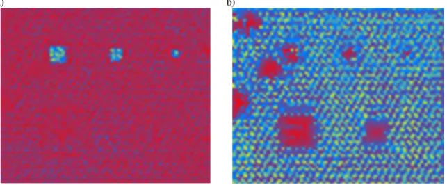
Figure 3 shows the results obtained on a part containing three square skin delaminations (top) and two core unbond areas (bottom) of different sizes. The horizontal dimension of each scan is 14 cm and the honeycomb unit cell diameter is 4.75 mm. The two images in figure 3 were obtained from the same data sets. Figure 3a shows a laser-ultrasonic C-scan of the inspected area obtained by filtering the signal with a 500 kHz
cutoff high pass filter and by plotting the maximum amplitude of the ultrasonic echoes in the first 10 µs of the signal. As seen in this image, the delaminations within the skin are well detected but not the disbonds between the skin and the honeycomb. From the arrival time of the first echo or the reverberation time between echoes, the depth of the delamination can be readily determined. Figure 3b shows a laser tapping C-scan of the frequency of the peak amplitude in the Fourier domain from signals in a much longer time gate (140 µs). In this case, the low frequency membrane vibration is dominant and the frequency, which varies from 30 to 120 kHz, is related to the size of the detachments. The higher is the frequency, the smaller is the size. As seen in Figure 3b, both delaminations within the skin and disbonds between the skin and the honeycomb are detected. The additional indications present on the left appear to be real disbonds. Also, the apparent noise in the image originates from the honeycomb structure, the skin being itself a detached membrane over each honeycomb cell. As mentioned before, it is not straightforward to determine the depth of a disbond from the vibration data alone. This example illustrates how this can be obtained by choosing a sufficiently short excitation pulse that produces both ultrasonic echoes and membrane vibrations. Also, Figure 4 shows a profile of the vibration frequency along a horizontal line crossing the two unbond areas in Figure 3b. The detachment on the right side has a larger vibration frequency, which is expected since its size is smaller. The figure also shows the generation of higher frequency modes when the laser beams are either outside or close to the edges of a disbond. This has been noted previously and it is very useful for detecting large disbonds in the continuous scanning mode.
a) b)
Figure 2. Sketch of side view a) of a delamination within the skin and b) of skin unbonds for a honeycomb structure.
a) b)
Figure 3. Results on a part containing three square skin delaminations (top) and two core unbond areas (bottom) of different sizes. The horizontal dimension of each figure is 14 cm and the honeycomb unit cell diameter is 4.75 mm. a) Ultrasonic echo C-scan (plot of the maximum amplitude after high pass filtering)
and b) vibration frequency C-scan (plot of the frequency of the maximum of the signal in the Fourier domain).
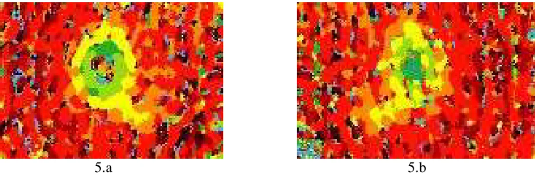
Figure 5 shows the laser tapping images obtained on a honeycomb structure having suffered a crush core impact on one side. The two images were obtained by scanning the part from the impacted side (5.a) and from the opposite side (5.b). The damaged area is clearly seen on figure 5.a. More surprisingly, the damaged area is also in figure 5.b. While these results will need more investigations, it indicates that crush core damage can possibly be detected from the opposite of the damaged surface, which can be of major importance for practical use since both sides of the part are not usually accessible for inspection. 30 40 50 60 70 80 90 100 110 120 0 20 40 60 80 100 120 140 Pos ition (m m ) F re q u e n c y ( k H z )
Figure 4. Profile of vibration frequencies along a horizontal line crossing the two unbond areas in Figure 3b.
5.a 5.b
Figure 5. Laser tapping inspection of an impact damage honeycomb part. The scan was made from the impacted side for figure 5.a and from the opposite side for figure 5.b.
Inspection of a Silicon Carbide Protecting Layer on a Carbon-Carbon
Substrate
Another example is the detection of detachments occurring between the SiC oxidation protecting layer and a C-C substrate. Carbon-carbon is widely used as thermal shield in rocket engines and on the fuselage of space vehicles, such as the US space shuttle. Since carbon is prone to reaction with oxygen above 450 ºC, C-C materials are generally protected by a ceramic coating such as one made of silicon carbide. The coating being porous, voids are produced with time by oxidation. If these voids grow to a critical size, the coating could get detached leaving the C-C substrate unprotected and subjected to severe oxidation.
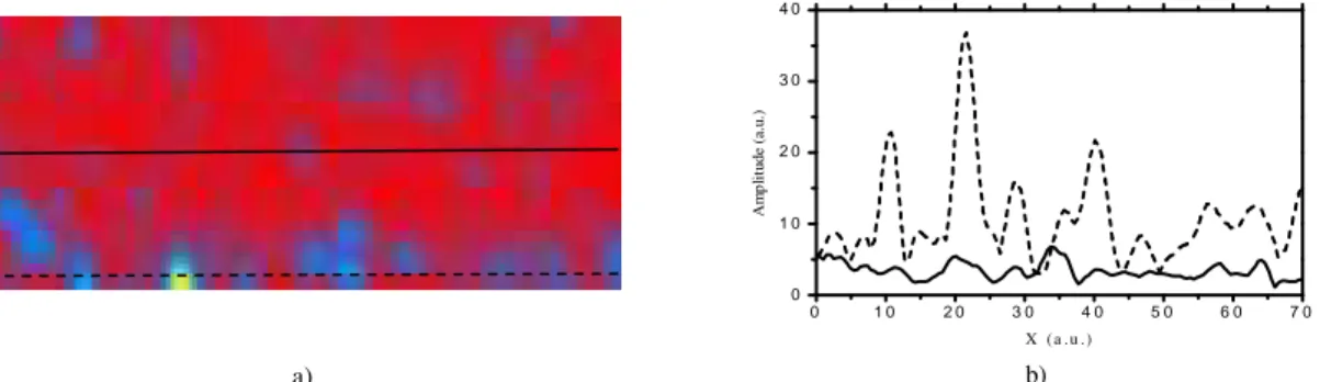
These coatings are however porous and strongly attenuate ultrasound. A pulse-echo ultrasonics approach was tried on the current C-C sample and no echo was observed. However, with the laser-acoustic technique described here, vibration signals are clearly observed when the coating is detached from the substrate. The results are shown in
Figure 5. Figure 5a presents a C-scan of the maximum amplitude of the data in the Fourier domain. Detachments are observed at the bottom of the figure near the edge of the specimen, as confirmed by visual observation. These disbonds are more clearly observed in Figure 5b, which shows the amplitude profile along the dotted line in Figure 5a. For comparison, Figure 5b also shows the amplitude along a well bonded line.
a) 0 1 0 2 0 3 0 4 0 5 0 6 0 7 0 0 1 0 2 0 3 0 4 0 A m p li tu d e (a .u .) X ( a .u .) b)
Figure 5. a) C-scan of the maximum amplitude of the laser-ultrasonic data in the Fourier domain. b) Amplitude profile along the solid and dotted lines on the C-scan in Figure 3a.
Conclusions
We have reported a novel technique for reliably detecting coating detachment and skin unbond in honeycombs. This technique, which can be called laser tapping, is based on the bulging and vibration of the detached skin or layer following absorption of a laser pulse. Detection of the induced surface motion is then made by a two-wave mixing photorefractive interferometer. This large etendue interferometer provides a mean to detect low frequency membrane vibrations while scanning optically rough surface parts. Detection of a large area at low frequency can be assured either by scanning system that stops for each signal acquisition or by the detection of higher harmonics of the fundamental membrane vibration. On honeycomb structures the proposed technique could also exploit the ultrasonic waves that are generated at the same time to get a more thorough and reliable inspection making it is possible to distinguish disbonds within the skin from detachment of the skin itself. Experimental results on coatings and on a honeycomb structure with core unbonds show the viability of the technique.
References
1. P. Cielo, X. Maldague, G. Rousset, C. K. Jen, Materials Evaluation 43, pp. 1111-1116 (1985).
2. A. Blouin, J.-P. Monchalin, Appl. Phys. Lett. 65, pp. 932-934 (1994).
3 M.P. Petrov, I.A. Sokolov, S.I. Stepanov, G.S. Trofimov, J. Appl. Phys. 68, pp. 2216-2225 (1990).
4 G. Rousset, D. Lévesque, L. Bertrand, X. Maldague and P. Cielo, Can. J. Phys. 64, pp. 1293-1296 (1986).
5. B. Campagne, A. Blouin, C. Néron, J.-P. Monchalin, Review of Progress in QNDE, 22, AIP Conference Proceedings, Melville, New York (2003), pp. 273-280.
6 P. Delaye, A. Blouin, D. Drolet, L.A. de Montmorillon, G. Roosen and J.-P. Monchalin, Journal of the Optical Society of America B 14, pp. 1723-1734, (1997).