Publisher’s version / Version de l'éditeur:
Vous avez des questions? Nous pouvons vous aider. Pour communiquer directement avec un auteur, consultez la première page de la revue dans laquelle son article a été publié afin de trouver ses coordonnées. Si vous n’arrivez pas à les repérer, communiquez avec nous à [email protected].
Questions? Contact the NRC Publications Archive team at
[email protected]. If you wish to email the authors directly, please see the first page of the publication for their contact information.
https://publications-cnrc.canada.ca/fra/droits
L’accès à ce site Web et l’utilisation de son contenu sont assujettis aux conditions présentées dans le site LISEZ CES CONDITIONS ATTENTIVEMENT AVANT D’UTILISER CE SITE WEB.
Inter-Noise 2009 [Proceedings], pp. 1-9, 2009-08-23
READ THESE TERMS AND CONDITIONS CAREFULLY BEFORE USING THIS WEBSITE. https://nrc-publications.canada.ca/eng/copyright
NRC Publications Archive Record / Notice des Archives des publications du CNRC :
https://nrc-publications.canada.ca/eng/view/object/?id=d7d3accc-5bc7-419f-90e0-505912057ae8 https://publications-cnrc.canada.ca/fra/voir/objet/?id=d7d3accc-5bc7-419f-90e0-505912057ae8
NRC Publications Archive
Archives des publications du CNRC
This publication could be one of several versions: author’s original, accepted manuscript or the publisher’s version. / La version de cette publication peut être l’une des suivantes : la version prépublication de l’auteur, la version acceptée du manuscrit ou la version de l’éditeur.
Access and use of this website and the material on it are subject to the Terms and Conditions set forth at Simplified method to estimate effectiveness of floor treatments (toppings and coverings)
http://www.nrc-cnrc.gc.ca/irc
Sim plifie d m e t hod t o e st im a t e e ffe c t ive ne ss of floor t re a t m e nt s (t oppings a nd c ove rings)
N R C C - 5 1 3 5 2
Z e i t l e r , B . ; S c h o e n w a l d , S . ; N i g h t i n g a l e , T . R . T . ; K i n g , F . u t h o r
A u g u s t 2 0 0 9
A version of this document is published in / Une version de ce document se trouve dans: InterNoise 2009, Ottawa, Ontario, August 23-26, 2009, pp. 1-9
The material in this document is covered by the provisions of the Copyright Act, by Canadian laws, policies, regulations and international agreements. Such provisions serve to identify the information source and, in specific instances, to prohibit reproduction of materials without written permission. For more information visit http://laws.justice.gc.ca/en/showtdm/cs/C-42
Les renseignements dans ce document sont protégés par la Loi sur le droit d'auteur, par les lois, les politiques et les règlements du Canada et des accords internationaux. Ces dispositions permettent d'identifier la source de l'information et, dans certains cas, d'interdire la copie de documents sans permission écrite. Pour obtenir de plus amples renseignements : http://lois.justice.gc.ca/fr/showtdm/cs/C-42
Simplified method to estimate effectiveness of floor
treatments (toppings and coverings)
Berndt Zeitlera Stefan Schoenwaldb Trevor Nightingalec Frances Kingd
Institute of Research in Construction National Research Council Canada Ottawa ON K1A 0R6 Canada
ABSTRACT
This paper examines methods to estimate the effectiveness of floor treatments (floor toppings) to control flanking transmission in lightweight construction. The paper proposes a new approach that is considerably faster to apply, and provides more information, than the traditional method of ISO 10848. Previous papers by T. Nightingale1,2 demonstrate that five factors affect flanking sound transmission: 1) Power Injected, 2) Attenuation with Distance, 3) Junction Attenuation, 4) Structural Attenuation, and 5) Power Radiated. This paper shows that by decomposing the flanking path into these five factors, and measuring the change in each due to adding the topping, it is possible to completely characterize the floor-floor path (the dominant flanking path in light weight constructions) by applying a floor topping in only a single room. Comparison of results from the traditional approach and the new approach show excellent agreement. The benefits of the new approach based on the five-factor method are the reduced test duration and cost, as well as the improved repeatability.
1. INTRODUCTION
Flanking transmission exists in all buildings and without proper design the sound insulation of the complete construction can be far less than that offered by the nominally separating element. In lightweight wood framed constructions the dominant flanking paths for both airborne and impact sources between horizontally and vertically adjacent rooms typically involve the floor
a
Email address: [email protected]
b
Email address: [email protected]
c
Email address: [email protected]
d
surface3, and some form of treatment – a floor topping – is required. Characterizing the effectiveness of a topping, or other treatment, to control flanking transmission can be done using the „traditional approach‟ where the flanking sound reduction index (Flanking-SRI), or the flanking normalized impact sound pressure level (Flanking-NISPL) if applicable, is measured before and after the treatment is applied. This traditional approach using ISO 108484 is straightforward enough, but in lightweight constructions the effectiveness of a topping to control flanking is a function of the joist orientation at the wall-floor junction, and is different than the effectiveness to control direct transmission5. Thus, to fully characterize the effectiveness of a topping three sets of measurements are required – two for flanking transmission involving the different floor-wall junctions, and one for direct transmission – both with and without the topping installed.
In the NRC-IRC Flanking Facility with eight rooms, four rooms on two levels, a topping can be installed and fully characterized (flanking for both directions, and direct transmission), but the process can be quite time consuming. Some floor coverings cannot be removed without damaging the subfloor, such as strip wood flooring, ceramic tile, etc., that are glued or nailed to the subfloor, which means the damaged layer must be replaced and re-characterized, otherwise leading to a repeatability error. This paper introduces a new approach that is much faster to apply, virtually eliminates the need to rebuild the substructure after evaluating a topping that is mechanically fastened to the subfloor, and enables characterization of topping effectiveness in the source room (for both airborne and impact sources), and in the receiving room.
2. FIVE FACTOR METHOD
This new approach, presented in this paper, takes advantage of Nightingale‟s five-factor method1. It not only optimizes measurement time and cost, but at the same time helps understand sound transmission better by separating the flanking paths into single components.
These single flanking components, called five factors, influence flanking sound transmission and will be described. Applied they can reduce the number of measurements needed to characterize the assemblies. Figure 1 shows the five factors that contribute to flanking sound transmission.
1. Power injected, which depends on the impedance match of airborne sound or impact source and receiver (floor). For impact sources this means the closer the source impedance is to the complex conjugate of the receiver impedance, the more power is injected into the floor.
2. Attenuation with distance from the source to the junction. The less internal damping the floor has, the stiffer the floor (small bending wave number) is, and the closer the source is from the junction, the more power gets transmitted to the junction.
3. Junction attenuation, which is to date not so well understood for lightweight construction, but describes the power attenuated at the junction itself due to the way of assembling the floor and wall junction. It is a function of the joist orientation and joist continuity and the way the wall and floor are coupled.
4. Attenuation with distance from the junction (on the flanking surface in the receive room), is similar in nature to structural attenuation (on the flanking surface in the source room); Again the internal damping and bending stiffness have strong impact.
5. Fifth is the power radiated into the receive room, which depends, as does the power injected, on the impedance match of the source (floor) and receiver (air volume in room). Added floor treatments can influence all factors, but practically junction attenuation is not affected for lightweight constructions.
Figure 1: Description of five factors that influence flanking sound transmission (1-5) and room names A-D.
Applying a topping to the source room can change factors 1 & 2, whereas applying it in the receive room can change factors 4 & 5. By combining results of measured paths for different or no applied treatment, the change of the factors, due to the topping, can be gained and added up appropriately to receive the total change of one full path due to adding a topping. This has a very important consequence. It is possible to isolate the effect of the topping in source and receive rooms, and from this extrapolate to cases not measured. For example the floor-floor path from room A to room B with topping in both rooms can be estimated by installing the topping in only room A, while shielding the separating wall to ensure that the floor-floor path is isolated. The change in the source room factors can be captured by measuring the impact sound insulation from room A to B with and without the topping. The receive room factors can be captured by moving the source into room B and repeating the measurements. To estimate the total floor-floor path with topping, the newly gained effect of the topping on the source and receive room factors are added to the bare floor-floor path. Which factors are affected by adding a topping is shown below in a more tabular form.
Table 1 shows which paths can change by adding a topping. The path description, i.e. AfBf, is abbreviated by the source room letter (A-D from Figure 1), the surface identifier (f: floor, c: ceiling, w: wall), the receive room letter (A-D), and the receive surface identifier (f, c, w). AfBf for example means the path from the floor of room A to the floor of room B. In the path descriptor bold red marks the room in which the topping was applied, and in the factor section the added bold red T‟s are the change of factors due to the topping.
Table 1: Cases required to measure the change in the five factors that influence flanking sound transmission. The path is described by source room (A-D as noted in Figure 1), source surface (floor, ceiling, and wall), receive room (A-D), and source room surface (f, c, and w). Rooms A and B are above, rooms C and D below. Red font indicates
topping applied in room.
2. Attenuation with Distance 1. Power injected by source depends on Impedance match 3. Junction Attenuation 5. Flanking sound power depends on radiation impedance 4. Structural Attenuation 1 2 3 4 5 4 5
A
B
C
D
Factor 1 2 3 4 5Path Power injected
Attenuation with Distance Junction Attenuation Structural Attenuation Radiation Impedance 1 AfBf f1 f2 ff3 f4 f5 2 BfAf f1+T1 f2+T2 ff3 f4+T4 f5+T5 3 BfAf f1+T1 f2+T2 ff3 f4 f5 4 BfAf f1 f2 ff3 f4+T4 f5+T5 Case Im p ac t & A ir b o rn e
This table could be expanded to include many different measurements (diagonal and vertical) to estimate the change in each of the factors due to adding the topping; however, this paper will restrict itself to the horizontal measurements. Looking at this table as a set of linear equations the unknown T-factors can be readily calculated by simple manipulation. Table 2 lists the manipulation (differences) needed to extract the unknowns in Table 1. By carrying out the difference listed in the Measurement Case column, the sum of the factors listed in the Influenced Factors column are calculated. In most of these Difference Cases the single factors cannot be totally separated, and are captured in a lump with other factors.
Table 2: Differences of measurement cases from Table 1 to calculate factors influenced by adding a topping.
For Difference Case D1, for example, which is used in the previously described straight forward method (both rooms with and without topping), the effect the topping has on all factors is calculated in one big lump. The floor-floor path is characterized with and without the topping in both rooms, and the difference made to obtain the influence of the topping on the floor-floor path. However, the single factors cannot be separated. Case D2 where the topping is only applied in the source room gives the change of factors 1&2 in one lump. Case D3, where the topping is applied in the receive room, delivers the change in factors 4&5. As mentioned above to measure both cases, D2 and D3, the topping needn‟t be moved and reapplied in the other room, but simply the source has to move from one room to the other.
Slowly, the benefits of the new method become apparent – time and material can be saved, because as was shown the topping only needs to be applied in one of the two rooms, and selected components of the flanking path are captured.
2. MEASUREMENT OF SINGLE PATHS
This section will show the effect a topping has on a wood-I joist floor on the single paths described above. Only results where the joists are parallel and discontinuous to the junctions will be presented below. The floor assembly is constructed of wood-I joists spaced 406 mm on centre (o.c.), with 150 mm batt insulation and, attached 19 mm OSB subfloor. The two layers of 16 mm thick gypsum ceiling are hung from resilient channels spaced 406 mm o.c. The topping is a wood raft of 16 mm plywood placed over 16 mm OSB stapled together. The raft is floating on a 9 mm foam interlayer.
A. Topping in source room
This section compares the change in source room factors (1 & 2) due to adding a topping for airborne transmission loss (TL) and normalized impact sound pressure level (NISPL), which are measured following the basic procedures of ASTM E336 and E1007.
Difference Case Nr. Measurement Case Nr. Influenced Factors Topping placement Source type
D1 2-1 1,2,4, & 5 both rooms Airborne & Impact
D2 3-1 1 & 2 source room Airborne & Impact
Figure 2: Change in airborne flanking TL or impact flanking NISPL of floor-floor path in horizontally separated rooms due to added topping in source room. Change in source room factors 1&2.
Figure 2 shows that for impact and airborne sources the topping influences factors 1&2 differently. The same is the case where the joists are parallel to the junction. The measurements of the effect are limited by the background noise, and the affected region is marked by the grey box. Both curves have a similar trend where the topping has little or no improvement in the low frequency range. The curves have a steep negative slope above 500 Hz where the floor and topping become decoupled due to the interlayer. The improvement is expected to continue to grow further to higher frequencies. The curves for the two sources are different for two reasons. First, because the impedance of the two sources is different and second, the airborne source provides reasonably uniform excitation, whereas the tapping machine is localized.
B. Topping in receive room
In this section the change due to the topping placed in the receive room is examined for the airborne and impact sources. Here only factors 4&5, structure attenuation after the junction and radiation, are influenced by the topping. Both curves have a similar trend as when the topping was placed in the source room, causing little improvement in the low frequency range and more toward the higher. Now with the topping applied in the receive room the effect is the same for the airborne and impact sources, which means that the change of sound power propagation attenuation and radiation in the receive room are similar for both sources.
IMPROVEMENT L im it s o f M e a s u re m e n t
Figure 3: Change in airborne flanking TL or impact flanking NISPL of floor-floor path in horizontally separated rooms due to added topping in receive room. Change in factors 4&5.
C. Comparison of single paths
Here the effect of the topping is shown for the airborne case in both directions. The influence of the topping applied in the source or receive room is the same (see Figure 4). For the effect of the topping to an airborne source this means that when applied in both rooms the change is double that of when only applied in one of the two rooms.
Figure 4: Change in airborne flanking TL of floor-floor path in horizontally separated rooms due to added topping in source or receive room. Change in factors 1&2 when topping applied to source room. Change in factors 4&5
when topping applied to receive room.
IMPROVEMENT L im it s o f M e a s u re m e n t IMPROVEMENT L im it s o f M e a s u re m e n t C h a n g e i n T L [ d B ]
The values being so close can be explained by reciprocity and also speaks to the quality of the measurement system.
3. PREDICTED RESULTS
This section presents results of the horizontal floor-floor path obtained by adding the change in different factors together. To obtain a prediction of the floor-floor path with toppings in both rooms, the bare floor-floor path is used as a reference and to it is added the effect of to the topping in the source room (factors 1&2) and in the receive room (factors 4&5).
A. Airborne source
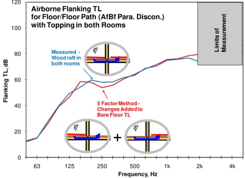
The results in Figure 5 compare the measured case 2 (from Table 1) with toppings in both rooms (blue curve) and the prediction, which is the sum of the bare floor measurement (case 1) and difference cases D2 and D3.
Figure 5: Prediction and measurement of airborne flanking TL of floor-floor path in horizontally separated rooms due to added topping in both rooms for parallel discontinuous junction cases.
Throughout most of the frequency range the measured and predicted data agree very well. Although not shown, the same is true for the case were the joists are perpendicular to the junction. In the upper frequency range, where the limits of the measurements begin, the calculated values over-predict the measured, due to the flanking sound transmission in the measurement. When the topping is applied in only one of the two rooms the measurement is not influenced by flanking sound transmission as much, because the TL is lower. This suggests that the prediction gives better estimates of the floor-floor path in the high frequency range than the direct measurement does.
B. Impact source
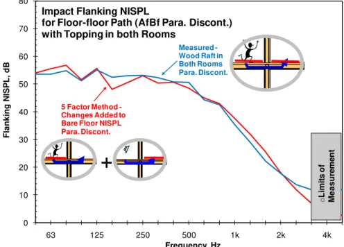
The final comparison is made for the impact source. Again the change of the source room factors 1 & 2 and receive room factors 4 & 5 are applied to the measurement of the bare floor. However, to reduces the number of measurements needed, the effect of the topping in the receive room (factors 4&5) is estimated using the airborne source and not the impact source. Figure 3 shows that these factors are the same for the airborne an impact sources. Figure 6 shows how well the predictions agree with the measurements. The flanking NISPL is quite steady below 250 Hz and
0 20 40 60 80 100 120 63 125 250 500 1k 2k 4k F la n k in g T L , d B Frequency, Hz Airborne Flanking TL
for Floor/Floor Path (AfBf Para. Discon.) with Topping in both Rooms
5 Factor Method -Changes Added to Bare Floor TL Measured -Wood raft in both rooms
+
L im it s o f M e a s u re m e n tthen begins to drop more steeply going to higher frequencies. In the upper frequency range, where the limits of the measurements begin, the calculated values over-predict the measured, due to the background noise influencing the measurement. As for the airborne source this suggests that the prediction in the upper frequency range is a better estimate of the floor-floor path with toppings in both rooms than that actual measurement.
Figure 6: Prediction and measurement of impact flanking NISPL of floor-floor path in horizontally separated rooms due to added topping in both rooms for parallel discontinuous junction cases.
4. SUMMARY AND CONCLUSION
This paper shows that Nightingale‟s five factor method can be readily applied to predict the floor-floor flanking sound transmission using the change in the flanking factors caused by adding a topping. There are several benefits to using this approach compared to the traditional straight forward one. The topping only needs to be applied in one of the two rooms. Note that this only work for isolated paths, in other words when the path of interest is by far the dominant path. Capturing effects by only applying the topping in one room is a very nice feature especially for toppings that cannot be removed without damaging the subfloor, because the effect of other toppings can still be measured on the other bare floor. If toppings are applied in both rooms the effect in the upper frequency range cannot always be captured due to the background noise or flanking limitation. Diagonal paths can also be used to capture the flanking path components. A further advantage of this approach is that fewer measurements are needed. After the bare subfloor has been characterized only one impact measurement is needed in the room with topping and two airborne measurements are needed - one in each direction. Also the full flanking path is understood better, because the change caused by a topping is separated into single components.
REFERENCES
1 T.R.T. Nightingale, R.E Halliwell, J.D. Quirt, “On the importance of the direct field in structure
borne transmission in framed construction”, in proceedings of ForumAcusticum 2005
2
J.D. Quirt, T.R.T Nightingale, “On a semi-empirical approach to predicting sound insulation in lightweight framed construction”, in proceedings of InterNoise 2007, Turkey
0 10 20 30 40 50 60 70 80 63 125 250 500 1k 2k 4k F la n k in g N ISPL , d B Frequency, Hz
Impact Flanking NISPL
for Floor-floor Path (AfBf Para. Discont.) with Topping in both Rooms
Measured -Wood Raft in Both Rooms Para. Discont. 5 Factor Method -Changes Added to Bare Floor NISPL Para. Discont.
+
o L im it s o f M e a s u re m e n t3 T.R.T. Nightingale, B. Zeitler, S. Schoenwald, F. King, “A hierarchy of flanking transmission
paths in lightweight wood frame construction”, in proceedings of InterNoise 2009, Ottawa
4 ISO 10848, “Acoustics- laboratory measurements of flanking transmission of airborne and
impact noise between adjoining rooms – Part 1: Frame document”, International Organization for Standardization, Geneva, 1998
5
T.R.T. Nightingale, F. King, “Bending wavenumber and associated damping”, in proceedings of The Thirteenth International Congress on Sound and Vibration 2006, Vienna