Publisher’s version / Version de l'éditeur:
Journal of Membrane Science, 441, pp. 148-157, 2013-04-10
READ THESE TERMS AND CONDITIONS CAREFULLY BEFORE USING THIS WEBSITE.
https://nrc-publications.canada.ca/eng/copyright
Vous avez des questions? Nous pouvons vous aider. Pour communiquer directement avec un auteur, consultez la
première page de la revue dans laquelle son article a été publié afin de trouver ses coordonnées. Si vous n’arrivez pas à les repérer, communiquez avec nous à [email protected].
Questions? Contact the NRC Publications Archive team at
[email protected]. If you wish to email the authors directly, please see the first page of the publication for their contact information.
NRC Publications Archive
Archives des publications du CNRC
This publication could be one of several versions: author’s original, accepted manuscript or the publisher’s version. / La version de cette publication peut être l’une des suivantes : la version prépublication de l’auteur, la version acceptée du manuscrit ou la version de l’éditeur.
For the publisher’s version, please access the DOI link below./ Pour consulter la version de l’éditeur, utilisez le lien DOI ci-dessous.
https://doi.org/10.1016/j.memsci.2013.03.053
Access and use of this website and the material on it are subject to the Terms and Conditions set forth at Polyethylene-based radiation grafted anion-exchange membranes for alkaline fuel cells
Sherazi, Tauqir A.; Sohn, Joon Yong; Lee, Young Moo; Guiver, Michael D.
https://publications-cnrc.canada.ca/fra/droits
L’accès à ce site Web et l’utilisation de son contenu sont assujettis aux conditions présentées dans le site
LISEZ CES CONDITIONS ATTENTIVEMENT AVANT D’UTILISER CE SITE WEB.
NRC Publications Record / Notice d'Archives des publications de CNRC:
https://nrc-publications.canada.ca/eng/view/object/?id=a62e5198-6f45-4ab5-b6d3-bfacba78c401 https://publications-cnrc.canada.ca/fra/voir/objet/?id=a62e5198-6f45-4ab5-b6d3-bfacba78c401
Polyethylene-based radiation grafted anion-exchange membranes for
alkaline fuel cells
Tauqir A. Sherazi1,2, Joon Yong Sohn3, Young Moo Lee1,4†, Michael D. Guiver1,5, †
1
WCU Department of Energy Engineering, College of Engineering, Hanyang University, Seoul 133-791, Republic of Korea
2
Department of Chemistry, COMSATS Institute of Information Technology, Abbottabad, 22060, Pakistan
3
Advanced Radiation Technology Institute, Korea Atomic Energy Research Institute, Jeongeup 580-185, Korea
4
School of Chemical Engineering, College of Engineering, Hanyang University, Seoul 133-791, Republic of Korea
5
National Research Council, Ottawa, Ontario, KIA OR6, Canada
† Corresponding Authors
Young Moo Lee, Tel.: +82-2-2220-0525. Fax: +82-2-2291-5982. E-mail: [email protected].
Michael D Guiver, Tel.: +1 613 993 9753; fax: +1 613 991 2384. E-mail address: [email protected]
*Manuscript
Abstract
Vinyl benzyl chloride was grafted onto ultra-high molecular weight polyethylene powder (UHMWPE) by radiation grafting. The grafted powder was subsequently fabricated into membrane by melt pressing. The effect of absorbed radiation dose on the degree of grafting (DG) is discussed. The melt-flow properties of PVBC grafted PE with low degree of grafting was conducive to forming homogeneous pore-free membranes, which was confirmed by scanning electron microscopic analysis. The grafted polyethylene membranes were post functionalized with trimethylamine, followed by alkalization to obtain anion-exchange membranes (AEMs). The structures of the resulting AEMs were characterized by Fourier transform infrared spectroscopy, which showed that the grafted membranes were successfully functionalized. The properties of the AEMs, including ion exchange capacity, water uptake, in-plane swelling, methanol uptake, methanol permeability, and hydroxide ion conductivity were investigated. The AEMs showed reasonably good chemical stability, as evidenced by the ion exchange capacity being maintained for a long duration, even in highly alkaline conditions. The membranes exhibited a maximum ionic conductivity of 47.5 mS cm−1 at 90 °C (30 mS cm-1 at 60 °C). Methanol permeability was found to be in the order of 10−8 cm2 s-1, which is considerably lower than that of Nafion®. The membranes have useful properties consistent with anion exchange membranes suitable for alkaline fuel cells.
Keywords:
Anion exchange membrane; Radiation grafting; Polyethylene; UHMWPE; Vinylbenzylchloride; Trimethylamine
1. Introduction
Fuel cells have been recognized as alternative energy devices for the future in both, mobile and stationary uses [1,2]. Among the different types of fuel cells, the majority of efforts have been directed towards the development of polymer electrolyte membranes fuel cells (PEMFCs) using proton exchange membranes (PEMs), because of their convenient features such as low-temperature operation, rapid start-up, high power density, which make them particularly suitable for vehicle and other mobile applications [3]. Although promising, PEMFCs still face some persistent obstacles to widespread adoption, of which the high cost of commercially available PEMs (typically Nafion®) and the dependence on expensive noble metal catalysts (typically platinum) are major contributors [4]. In recent years, the development of anion exchange membranes (AEMs) for anion exchange membrane fuel cells (AEMFCs) has gained rapidly increasing interest, because of their advantage over alkaline fuel cells (AFCs). This is due to the replacement of liquid electrolyte with solid electrolyte membrane, which reduces the adverse effect of CO2. AEMFC also have a cost advantage over PEMFCs because significantly less noble
metal catalyst or non-noble metals can be utilized in the electrodes [5-6]. Since catalysts are generally more stable in basic media, non-precious metals such as nickel and silver [7] can be used as cathode catalysts, which have the potential to greatly reduce the cost of the fuel cells. In AEMFCs, the AEM separates the reactant gases and conducts the hydroxide ions from the anode to the cathode.
Considerable efforts have been focused on the preparation of AEMs through chloromethylation of polymers, followed by quaternization and alkalization steps [8–11]. However, chloromethylation reactions require chloromethyl ether, which is a potent carcinogen, harmful to human health [12]. The synthesis of AEMs through radiation grafting of vinylbenzyl chloride (VBC) onto polymer matrices has been shown to be an effective way of avoiding the use of chloromethyl ether [13-15]. Moreover, electrolyte membranes containing grafted units, due to their comb-shaped nanoscale structural organization, exhibit high ionic conductivity over a wide range of humidity [16]. Radiation grafting, employing ionizing radiation such as -rays and electron beams, is an advantageous grafting technique because (1) reactions can be easily controlled by
adjusting the experimental parameters; (2) there is a relatively uniform formation of radicals with a thickness of the order of mm; (3) the process is free from contamination because it does not need initiator for radical formation, so that the purity of the processed products may be maintained [17-18].
Many commercially available fluorinated polymers, such as PVDF [19,20], poly(tetrafluoroethylene-co-hexafluoropropylene) (FEP) copolymer [13, 19-21], ETFE [22], PTFE-FEP [23], etc., have been the subject of radiation-induced grafting with vinylbenzyl chloride followed by quaternization and alkalization for AEMs. However, in the context of radiation grafting, the main disadvantage associated with PTFE is that it exclusively undergoes main-chain scission due to the relatively stronger C–F bond as compared with the C–C bond, and a relatively low irradiation dose can effectively reduce the molecular weight of the PTFE [24-25]. Moreover, some of the fluorinated polymers are easily degraded in basic media [19,26]. Thus, fluorinated polymers may be less suitable polymer substrates for radiation-induced grafting and also for AEMFC application. Furthermore, the ionic conductivity of the resulting AEMs studied so far is considerably lower compared with Nafion® membranes, thus needing further improvement.
The present study focuses on the grafting of poly(vinylbenzyl chloride) onto ultra-high molecular weight polyethylene (UHMWPE) powder (hereafter represented by PE) by gamma (60Co) irradiation. The purpose of grafting vinylbenzyl chloride groups is that they are readily amenable to quaternization, ultimately providing inexpensive polyelectrolyte membrane materials. The main advantages of using UHMWPE are that (1) it is inexpensive in comparison with fluoropolymers; (2) polyolefin copolymers generally have excellent bulk physical/chemical properties; (3) it has a tendency for crosslinking upon exposure to gamma irradiation; (4) it is relatively stable towards alkaline conditions. Ultra-high molecular weight polyethylene grafted poly(vinylbenzyl chloride) (PE-g-PVBC) powder was then fabricated into membrane by compression moulding followed by quaternized with TMA and subsequently alkalized to form the AEMs. The morphology of the grafted membranes was analyzed by SEM, while Fourier transform infrared (FTIR) spectroscopy was utilized to characterize of structure and functionality of the AEMs. The ion exchange capacity (IEC), water uptake (WU), in-plane swelling,
methanol uptake (MU) was investigated. Furthermore, thermal gravimetric analysis (TGA) and differential scanning calorimetery (DSC), methanol permeabilities and hydroxyl ion conductivities are also included.
2. Experimental 2.1. Materials
UHMWPE (MW = 300,000-600,000) powder, vinylbenzyl chloride (mixture of 3- and 4-isomers, 97%), trimethylamine (TMA) solution ~45 wt. % in H2O were purchased
from Sigma–Aldrich (Milwaukee, WI, USA). Other chemicals, including, methanol, toluene, sodium hydroxide and hydrochloric acid were analytical grade and were also purchased from Sigma–Aldrich and used as received. Water obtained through a Millipore water purification system was used throughout this study.
2.2. Membrane Preparation
2.2.1. Polymer irradiation and grafting
A measured amount of PE powder was washed in methanol and then dried. The PE powder was placed in screw-cap air-tight glass vials sealed with rubber septa. The irradiation of the polymer was conducted in an inert atmosphere, by purging the glass vials with N2 gas, then filling them with N2 using a syringe. The samples were inserted
into the irradiation chamber, and exposed to 60Co -rays for absorbed doses ranging from 3-25 kGy at a calibrated dose rate of 1 kGy/h. Monomer concentration in methanol as solvent was also optimized to obtain maximum grafting yield. The pre-irradiation grafting method was adopted, whereby the monomer (vinylbenzyl chloride diluted in methanol) was added to the irradiated PE powder, immediately after the samples were removed from the irradiation chamber. After the mixture was stirred for 8 h at 60 °C, the resulting PVBC-grafted PE (PE-g-PVBC) was washed with toluene several times to remove any trapped monomer or homopolymer (PVBC), and then dried in a vacuum oven at 60 °C to a constant weight. The percentage degree of grafting (%DG) was determined by the weight increase of the samples as given by:
100 % o o g W W W DG (1)
Where Wo is the measured weight of the original substrate polymer powder and Wg is the
measured weight of the grafted powder at a given condition, respectively.
2.2.2. Membrane formation
The PE-g-PVBC powders with different degrees of grafting were melt pressed into membranes before quaternization, to convert them into AEM materials. Melt pressing was conducted at 10000 psi at a set plate temperature of 220 °C for 15 min, providing films with an average thickness in the range of 85-95 μm.
2.2.3. Quaternization and Alkalization
PE-g-PVBC membranes in vials were stirred in about 30 mL of 50% aqueous solution of TMA at about 35-40 °C for 36 h. After completion of the reactions, the membranes were washed with DI water to remove excess TMA and then dried at 60 °C overnight, followed by vacuum at 70 °C for 8 h. The membranes reacted with TMA were treated with 1 M NaOH at room temperature for 48 h to exchange the chloride ions for hydroxide ions. The membranes were washed thoroughly to remove residual NaOH and stored in DI water prior to analysis. PE-g-PVBC membranes quaternized with TMA and reacted with NaOH are denoted as PE-g-PVBC-TOH.
Scheme 1. Synthesis scheme of radiation grafted anion exchange membranes
2.3. Membrane characterization
The ATR-FTIR analyses of control PE, PE-g-PVBC, PE-g-PVBC-TOH membranes were performed on a FTLA2000 Series FTIR spectrometer. A scanning electron microscope (SEM, LEO 440, UK, magnification 5× to 300,000×, resolution of 3.5 nm) was used for the morphological analysis of the pristine and grafted samples to ensure uniform grafting. For SEM analyses, the gold-coated membrane samples were placed in the SEM sample chamber and analyzed at a magnification of 50000× for surface and 750× for cross-sectional views. The detector used was a secondary electron (SE) detector. The thermal stability of the membranes was investigated by thermogravimetric analysis using a TA Instruments thermogravimetric analyzer (TGA) instrument Model Q 500. Preheating of the polymer samples was performed at 100 °C for 40 min under nitrogen atmosphere to remove moisture. The samples were then heated at 10 °C/min from 50 to 700 °C under nitrogen atmosphere to obtain percentage weight loss with respect to temperature. The melting temperature of each membrane was determined by using a differential scanning calorimeter (DSC, TA Instruments DSC Q20 thermal analyzer). The DSC curves of the polymers were recorded in the temperature range from 30 °C to 160 °C at a heating rate of 10 °C/min under a flow of nitrogen. To assess the
chemical stability, anion exchange membrane samples of 5 cm diameter were immersed in 1 M NaOH solution at 60 °C for time period ranging 10 to 120 h. After contact, the membranes samples were separated, and washed with DI water until the absence of the alkalinity in the effluent, followed by IEC determination. In another experiment, the test samples were immersed in NaOH solutions of different concentrations (1 M to 10 M), while maintaining the temperature and immersion time constant i.e. 60 °C and 120 h respectively.
2.4. Ion-exchange capacity (IEC) measurements
The ion-exchange capacities (IECs) of the PE-g-PVBC-TOH and PE-g-PVBC-GOH membranes were measured in triplicate by the classical back titration method to evaluate the hydroxide ion transport capacity. Accurately weighed samples were equilibrated with 25 mL 0.05 M HCl solution for 48 h, after which the HCl solution was back titrated by 0.05 M NaOH solution. IEC values of the samples were calculated as the following relation: ) ( . . 2 1 1 meqg M HCl n HCl n IEC dry (2)
where n1.HCl and n2.HCl are the amount (mmol) of hydrochloric acid required before
and after equilibrium, respectively, and Mdry is the mass (g) of the dried sample. The
average value of the three samples calculated from Eq. (2) is the IEC value of the measured membrane.
2.5. Water and MeOH Uptake
Percentage water and methanol uptake of PE-g-PVBC-TOH membranes were measured by their weight difference after soaking in DI water, and also in methanol at 20 °C for 24 h. The weight percentage uptake was determined by the following equation.
d d w W W W Uptake(%) (3)
where Wd and Ww are the weight of the dry and fully hydrated membrane, respectively.
In-plane swelling was also determined by measuring dimensional change in the membranes after immersion in water at 20 °C and 60 °C for 24 h.
2.6. Methanol Permeability
Methanol permeability (P, cm2 s−1) was measured at 30 °C using a two-chamber diffusion cell method. Prior to the measurement, each membrane coupon (diameter = 2.5 cm) was soaked in water to fully hydrated state for at least 1 day. One chamber (80 mL) contained 10 M (34 wt.%) methanol solution and the other chamber (80 mL) was filled with DI water. The diffused methanol was periodically measured using a Shimadzu GC-1020A series gas chromatography machine. Peak areas were converted into methanol concentration with a calibration curve.
The methanol permeability was calculated by the following equation:
) ( . . . ) ( A o B B C t t L DK V A t C (4)
where CA and CB are the methanol concentrations of the membrane feed side and permeate side, respectively. A, L and VB are the effective area, membrane thickness and the liquid volume of permeate compartment, respectively. DK is defined as the methanol permeability. to is the time lag.
2.7. Hydroxide Ion Conductivity
The impedance of the membranes was determined by A.C. impedance spectroscopy using a four-point probe electrode system which was connected with an impedance/gain-phase analyzer (Solartron 1260) and an electrochemical interface (Solartron 1287, Farnborough, Hampshire, UK) or (BioLogic VMP3 and BioLogic VSP). The electrode system was installed in an electrically shielded thermo- and hygro-controlled chamber. The impedance measurement was carried out at a given temperature and relative humidity (RH). The OH¯ conductivity (σ) was obtained from the following equation:
σOH
− (S cm−1) = L / RA (5)where σ is the hydroxide conductivity (S/cm), R is the ohmic resistance of the membrane sample (Ω), L is the distance between the electrodes to measure the voltage drop (cm),
and A is the cross-sectional area of the membrane sample (cm2). The impedance of each sample was measured repeatedly to ensure reproducibility for the measured data.
3. Results and Discussion
3.1. Effect of the irradiation dose and monomer concentration on grafting
In contrast with other grafting studies for AEM development, PE powder, rather than membrane, was used for the grafting reaction. Grafting on powder is considered a good experimental strategy for improving the uniformity and distribution of grafted vinyl benzene monomer throughout the amorphous sites of the polymer, where grafting takes place, which subsequent to film formation, allows a more uniform graft distribution of alkylamine groups [27-28]. The relationship between the DG of VBC into PE at 60 ºC with different pre-irradiation doses and monomer concentrations were studied as presented in Fig. 1. The grafting yield increases with increasing irradiation dose, which is simply attributed to the increased concentration of free radicals in the grafting system. However the trend is not linear; at irradiation doses ranging from 1 to 7 kGy, the rate of
DG increase was faster than that above 7 kGy. The higher absorbed dose causes the
formation of PVBC homopolymer along with grafting, which increases the viscosity and blocks the penetration of the monomer to access the active sites of the PE polymer. Methanol is selected as solvent as being an effective medium for grafting of VBC onto PE because it acts as a non-solvent for grafted polymer (PE-g-PVBC), resulting in restricted chain mobility, hence increased radical lifetime and, consequently, enhanced grafting kinetics [29]. The DG increased more rapidly with increasing monomer concentration up to 50% and thereafter, only a slight increase with increased concentration was observed up to 80%, with DG falling slightly at 100% monomer concentration as illustrated in Fig. 1 (secondary axis). This trend is attributed to swelling behavior of PE during grafting and availability of the monomer to the grafting sites [27]. An increase in concentration of the VBC monomer solution in methanol simultaneously increases the monomer availability as well as the monomer diffusion to the grafting sites, which in turn enhances the degree of grafting. However, undiluted monomer (i.e. in the
absence of methanol) may lead to homopolymerization, which plausibly hinders monomer access to the active grafting sites, resulting in a decrease in DG.
Fig. 1. Variation of %DG with pre-irradiation absorbed dose (monomer concentration: 50%) and variation of %DG with monomer concentration (absorbed dose: 10 kGy; N2
atmosphere; solvent: methanol; grafting temperature: 60 ºC; grafting time: 8 h) 3.2. Preparation of AEMs
The PVBC-grafted PE powder was fabricated into membrane by hot-press processing, which provided reactive sites evenly distributed throughout the thickness of the membrane, followed by quaternization and alkalization.
In many previous studies, a wide variation in the post grafting degree of substitution (DS) of ionic moiety was observed when membrane (rather than powder in the present study) was used as substrate [30-31]. The origin of this variability arises from local DG inhomogeneities over the thickness and area of the membrane. One of the advantages of the post-grafting film formation as adopted in the present study is that the film is free from the non-uniform and localized grafting. Localized and inhomogeneous grafting can cause film brittleness and originate additional resistance during ionic conduction through the film, which would adversely affect the performance of AEMs.
The observed lower-than-theoretical DS of anion exchange sites at high DG is primarily related to limitations in the penetration of the quaternizing agent into the graft sites after
membrane formation. In the literature, a wide range of DG is reported in connection with radiation grafted membranes intended for application in fuel cells. Yet, practical DGs for membranes for use in single cells are typically between 15% and 40% [32], depending on the polymer structure. The limits are determined on the one hand by the threshold for graft penetration through the entire thickness of the membrane at low graft levels, below which, the membrane is not expected to have appreciable conductivity, rendering it useless for the fuel cell. On the other hand, an upper practical limit for the graft level is given by the excessive swelling of the polymer and associated deterioration of membrane integrity, limiting the applicability and lifetime of the material. It is observed in the present study that higher values of %DG can be obtained by increasing the total dose by the pre-irradiation grafting technique. However, the fabrication of grafted powder into membrane is a matter of concern since membrane can be made from grafted powder with
DG up to 17.4% while higher % DG is unsuitable, likely because the polar nature of the
grafted PVBC onto non-polar PE main chain leads to phase separation during membrane formation. This phenomenon also caused imperfections in the membranes prepared from 17.4% DG powder. Thus, the 17.4% DG membrane was not used for following characterization studies. Consequently, the membranes with DG only up to 15.7% are considered for characterization in this study.
Fig. 2 shows the relationship between DG and the theoretical and experimental
IEC, which increases with the DG. Theoretical IEC was calculated on the basis of DG
considering 100% degree of amination (assuming that each benzyl unit is substituted with one TMA group). There is a good agreement between experimental and theoretical values of the IEC at lower DG; however the deviation between the calculated and experimental
IEC values increases with increasing DG, which may be explained by incomplete
quaternization of PE-g-PVBC caused by limitations in reactant penetration. Table 1 provides a summary of membranes of different DG (denoted by the polymer code suffix) used to obtain AEMs having various IEC values.
IEC (theoretical) of PE-g-PVBC-TOH membranes is determined using the following
equation: ) ( ) / ( 100 / 1000 1 meq g M M DG DG M DG IEC TMA VBC VBC (6)
or simply by ( ) 39 . 1 100 56 . 6 1 meqg DG DG IEC (7)
Table 1. Summary of radiation grafting conditions and the resulting DG and IEC of the membranes assuming 100% amination. (Dose rate = 1 kGy/h, monomer conc. = 50% in methanol, grafting time = 8 h, grafting temperature = 60 °C)
AEM Total
Dose (kGy)
DG (%)
IEC (Calc.) IEC (Exp.) (meq g-1) PE-g-PVBC-8.3 3 8.3 0.49 0.40 ±0.03 PE-g-PVBC-12.6 5 12.6 0.70 0.49 ±0.035 PE-g-PVBC-15.7 7 15.7 0.84 0.58 ±0.03 PE-g-PVBC-17.4 10 17.4 0.92 0.63 ±0.032 PE-g-PVBC-20.1 15 20.1 1.03 0.75 ±0.027 PE-g-PVBC-23.1 20 23.1 1.15 0.83 ±0.035 PE-g-PVBC-24.6 25 24.6 1.2 0.91 ±0.033 0 5 10 15 20 25 0.0 0.3 0.6 0.9 1.2 Io n E x c h a n g e C a p a c it y ( m e q g -1 ) Degree of Grafting (%) IEC-Theoretical IEC-Experimental
Fig. 2. Relationship between DG and theoretical (assuming 100% amination, no side reactions, and no trapped homopolymer in the intermediate PE-g-PVBC membranes) and
experimentally determined IECs (meq g-1) for the AEMs.
3.3. Characterization of graft membranes
The chemical structures of PE, PE-g-PVBC, PE-g-PVBC-TOH membranes were analyzed by ATR-FTIR spectra, as shown in Fig. 3.The absorption bands in the ranges of
2825–2870 and 2870–2960 cm−1 are characteristic of symmetric and asymmetric stretching of aliphatic –CH2 groups, while C–H stretching and bending absorption bands
for PE base polymer appeared at 1472 cm−1 and 1463 cm−1 respectively.
The absorption at 826 cm–1 is related to C–H deformation of para/meta substituted benzene ring. The ATR spectra of PE-g-PVBC showed a band at 1285 cm–1, which is due to H2C–Cl wag of the benzyl chloride group. In the spectra of PE-g-PVBC-TOH, the
CH2–Cl wag of benzyl chloride groups at 1285 cm–1 disappeared, confirming the
successful quaternization of PE-g-PVBC membrane.
Fig. 3. ATR-FTIR spectra of (bottom to top) i) Pristine PE, ii) PE-g-PVBC (DG=12.6%), iii) PE-g-PVBC (DG=15.7%), iv) PE-g-PVBC-TOH (DG=12.6%) v) PE-g-PVBC-TOH
(DG=15.7%) membranes.
The bands at 1100 cm-1, 1126 cm-1 and 1260 cm-1 may be due to C–N stretching. The bands at 1400 cm-1 and 1358 cm-1 in PE-g-PVBC-TOH spectra are ascribed to –CH3
bending. The broad absorption band in the range of 3400-3200 cm-1 in PE-g-PVBC-TOH membrane is attributed to O–H stretching in H2O. These spectral features provide
supporting evidence that PVBC was grafted into the PE membrane and subsequently quaternized with TMA.
3.4. Scanning electron microscopy (a) 100 n m X 50,000 100 n m X 50,000 (d) 1 0 μ m X 750 (b) 100 n m X 50,000 100 n m X 50,000 (e) 1 0 μ m X 750 (c) 100 n m X 50,000 100 n m X 50,000 (f) 1 0 μ m X 750
Fig. 4. SEM micrographs of: membrane surface at magnification 50,000× of (a) pristine PE, (b) PE-g-PVBC (DG = 12.6%), (c) PE-g-PVBC (DG = 15.7%); and membrane cross-section at 750× of (d) pristine PE (e) PE-g-PVBC (DG = 12.6%) (f) PE-g-PVBC-TOH
‒ The SEM images of compression molded membranes of pure PE and PE-g-PVBC are shown in Fig 4. The surface of pristine PE membrane (Fig. 4a) is observed to be smooth and crack free indicating complete melting and flow. The cross-sectional view of the same membrane (Fig 4d) also exhibits smoothness and uniformity, confirming that the compression molding technique and conditions applied are appropriate for membrane formation from PE powder, which is insoluble in almost any solvent. Phase separation during melt pressing of grafted powder could be expected due to grafting of polar monomer VBC onto non-polar polyethylene backbone. DSC measurements, discussed in the following section, indicate that there are only slight differences in the melt temperature upon grafting, which suggests that distributed graft units within the membrane can be obtained by applying the same membrane forming conditions as those for pristine PE. Fig. 5b shows the surface image of a membrane with 12.6% DG, which has greater surface roughness than pristine PE due to the presence of PVBC grafts. The cross-section view (Fig 5e) shows overall similar morphology throughout the thickness of the membrane, suggesting that the grafted units are uniformly distributed. Some phase separation effect is evident with further increasing the DG to 15.7% as represented by Fig. 5c; the membrane surface appears to contain a few small pores of 2-10 nm diameter. The cross-sectional image (Fig 5f) also shows similar morphology, suggesting that the PVBC grafts are uniformly distributed throughout the thickness of membrane. The phase separation could possibly lead to discontinuity in the conducting channels, resulting in the observed increase in resistance to ionic conduction.
Fig. 5. TGA thermograms of control PE, PE-g-PVBC, PE-g-PVBC-TOH
The thermal stability of the membranes was evaluated by TGA under identical drying and heating conditions and all the samples were pre-heated to remove free water, since the membranes under analysis are strongly hydrophilic. From Fig. 5, no weight loss was observed up to 160 °C, signifying that any absorbed water was removed. The TGA curve of PE shows excellent thermal stability, having negligible weight loss up to 460 °C and exhibits a single main chain degradation step started at 460 °C and culminating with a 100 % weight loss at 530 °C. The 100% weight loss was attributed to the sole carbon and hydrogen elemental composition of PE, resulting in completely volatile degradation products.
After grafting of VBC monomer onto PE, the polymeric product contains two different structure types; one is the aliphatic backbone of PE and the other is grafted PVBC aromatic units, which was confirmed by the two distinct weight loss steps appearing in curves (b) and (c) of Fig. 5. PE-g-PVBC behaves similarly to non-grafted-PE at temperatures up to 390 °C, but above this temperature, the first onset point is due to the degradation of grafted-PVBC units. The second degradation onset at 460 °C is due to the aliphatic PE backbone. The curves (d) and (e) in Fig. 5 representing
PE-g-PVBC-TOH with DG value 8.3% and 12.6%, respectively, behave differently in their degradation pattern. The first weight loss steps at ~170 °C are related to the decomposition of –CH2N(CH3)3OH groups. The next weight loss at 390 °C,
corresponding to aromatic group degradation, overlaps with the final PE chain degradation step that starts at ~ 455 °C.
Fig. 6. DSC thermogram of control PE, PE-g-PVBC, PE-g-PVBC-TOH
The DSC curves of PE, PE-g-PVBC, PE-g-PVBC-TOH, are shown in Fig. 5. The strong transition (endothermic peak) at 131 °C represents the Tm of control PE. The
sharpness of the peak represents the significant presence of crystalline regions in the polymer. Negligible decreases in Tm transitions were observed after PE was grafted with
PVBC or after quaternization, indicating that the original crystallites in the modified membranes remained intact, since Tm is a function of changes in the crystalline structure.
perhaps in areas close to, but not penetrating, the surface of the crystallites. In the DSC curves, this results in a dilution effect on the crystallinity of PE. Negligible differences in the Tm values, but significant decreases in the areas under the curve, represent the dilution
effect upon grafting and subsequent quaternization.
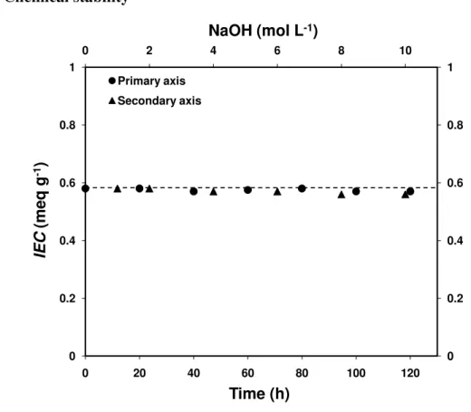
3.6. Chemical stability 0 0.2 0.4 0.6 0.8 1 0 2 4 6 8 10 0 0.2 0.4 0.6 0.8 1 0 20 40 60 80 100 120 NaOH (mol L-1) IE C (meq g -1) Time (h) Primary axis Secondary axis
Fig. 7. Variation of IEC of PE-g-PVBC-TOH (DG 15.7%) membranes with increasing concentrations of NaOH and exposure times at 60 °C.
The chemical stability of the AEM was determined by observing changes in IEC values with time and by varying the concentration of NaOH solution, as shown in Fig. 7. For this purpose PE-g-PVBC-TOH with a DG of 15.7% was selected, which had an initial IEC value of 0.58 meq g-1. There was a negligible change in IEC with time, even after 120 h treatment with 1 M NaOH at 60 °C. In other experiments, membranes with the same specification were treated with different concentrations of NaOH at 60 °C for 120 h. As shown in Fig. 7, only very minor changes in IEC were observed, even on
exposure to 10 M NaOH. The stability of these membrane is attributed to the high chemical stability of the PE polymer and to the stability of trimethylammonium groups, exhibiting negligible degradation under alkaline conditions at elevated temperatures when properly hydrated[33]. Moreover, the absence of -hydrogen atoms in the structure of PE-g-PVBC-TOH prevents Hoffmann-type elimination degradation from occurring in the hydroxide form, also increasing the ammonium ion stability [34-35].
3.7. Water and methanol uptake
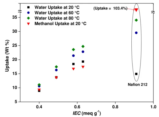
0.4 0.6 0.8 1.0 5 10 15 20 25 30 35 40 Water Uptake at 20 °C Water Uptake at 60 °C Water Uptake at 80 °C Methanol Uptake at 20 °C U p ta k e ( W t % ) IEC (meq g-1) 0 10 (Uptake = 103.4%) Nafion 212
~
~
~
~
Fig. 8. Variation in water and methanol uptake of PE-g-PVBC-TOH membranes with IEC
Table 2. Physico-chemical properties of PE-g-PVBC-TOH membranes compared to Nafion® 212 PE-g-PVBC-TOH membranes, DG (%) IECexp (meq g-1) Hydroxide ion conductivity, POH (mS cm-1) Water uptake (Wt%) In-plane swelling (%) Methanol uptake (wt%) MeOH permeability PMeOH (cm 2 s-1) 30 °C 90 °C 20 °C 60 °C 80 °C 20 °C 60 °C 20 °C 30 °C 8.3% 0.40 6.0 24.9 8.93 10.58 11.09 9.46 9.89 9.40 1.5 × 10⁻⁸ 12.6% 0.49 7.6 47.5 13.73 16.31 17.46 14.67 15.06 13.66 2.72 × 10⁻⁸ 15.7% 0.58 4.6 23.1 18.44 21.41 23.58 22.53 23.09 16.77 5.92 × 10⁻⁸ 17.4% 0.63 ‒ ‒ 19.31 22.81 24.70 23.05 23.55 17.47 ‒ Nafion® 212 0.91 77.4a 154.2a 14.93 29.53 34.03 39.6 57.39 103.4 1.38 × 10⁻⁶ a
proton conductivity values measured for Nafion® 212
Water uptake in membranes is related to the number of available ion exchange sites and has a profound effect on ionic conductivity and mechanical properties [36]. High water uptake generates solvated ionic species and facilitates their migration by broadening the ion transfer channels, which is necessary for high conductivity. However, there is strong trade-off relationship between ionic conductivity and mechanical properties, particularly if WU is excessive. The methanol uptake is also an important parameter related to the methanol permeability of the membrane, i.e. a membrane with high methanol uptake is also generally highly methanol permeable. Water and methanol uptake (wt%) at various temperatures for PE-g-PVBC-TOH with IEC in the range of 0.40-0.63 meq g-1 are compared with Nafion® 212 and are shown in Fig. 8. In-plane dimensional swelling is also presented in Table 2.
As expected, the WU increases with increasing IEC because of the increase in the hydrophilicity imparted by the quaternization reaction. However the WU trend is different from Nafion® 212, when considering the effect of temperature. For their low
IEC values, WU is relatively higher for PE-g-PVBC-TOH membranes than for Nafion.
However, the PE-g-PVBC-TOH membranes had a much lower WU temperature dependence than Nafion, which is also observed in the in-plane swelling results; PE-g-PVBC-TOH membranes exhibited minimal dimensional changes from 20 °C – 60 °C compared with 45% for Nafion® 212. Low in-plane swelling is desirable in reducing mechanical failures in the membrane electrode assembly (MEA), since high in-plane swelling deforms the membrane electrode interface. A beneficial property of the PE-g-PVBC-TOH membranes is that increasing temperature increases the ionic conductivity without loss of dimensional stability.
One of the promising features of the PE-based AEMs is their almost complete insolubility in methanol [37], which results in methanol having little or no direct effect on the dimensional swelling of PE-g-PVBC-TOH. Similar to water uptake, increased methanol uptake correlates with increasing IEC, which can be attributed to the presence of quaternary amine. As shown in Fig. 8, methanol uptake increases gradually with increasing IEC, but the PE-g-PVBC-TOH membranes reach a maximum value of ~17.5% as compared to over 103% for Nafion® 212, measured at 20 °C. Swelling of AEMs
strongly influences the transport phenomena, including ionic conduction and methanol permeability.
3.8. Methanol permeability
Fig. 9. Methanol permeability through PE-g-PVBC-TOH membranes at 30 °C
Methanol can be used as fuel in solid alkaline fuel cells, thus measuring methanol permeability is one of the key parameters to evaluate the AEM for alkaline fuel cells application. Methanol permeability is the product of the diffusion coefficient and the sorption coefficient and is used to describe the transport of methanol through membranes. Diffusion or leakage of the fuel across the membrane from anode to cathode leads not only to power loss from mixed potentials, but also other undesirable consequences, such as complicated water and thermal management. Thus, high methanol crossover is a serious obstacle for membranes in DMFC applications. Methanol permeation through hydrophilic ion-exchange membranes can be controlled by various factors such as hydrophilic channel size, water content, membrane compactness, additives, and operation conditions [38].
The methanol permeabilities of PE-g-PVBC-TOH membranes with DG in the range of 8.3–15.7% compared with Nafion® 112 are presented in Fig. 9. The difference in the starting points in Fig. 9 represents the delay for the first trace of methanol to be observed across the membrane (e.g. the first methanol concentration after continuous analysis for PE-g-PVBC-TOH, DG 8.3% was at ~60 h). The methanol permeation coefficients for the AEMs with DGs of 8.3%, 12.6% and 15.7%, calculated from a dynamic model of the system based on Fick’s law, are 1.5 × 10⁻⁸, 2.7 × 10⁻⁸ and 5.93 × 10⁻⁸ cm2 s−1, respectively.
The methanol permeability of the PE-g-PVBC-TOH membranes follows an expected trend of increasing with the quaternary amine content, because the imparted hydrophilicity contributes to increased liquid uptake and methanol permeability causing broadening of the ionic channels. The methanol permeability of PE-g-PVBC-TOH membranes are in the order of 1-6 × 10⁻⁸ cm2 s-1,which are approximately one to two orders of magnitude lower than Nafion® 212. It is expected that if the IEC value approached that of Nafion® 212, the methanol permeability would still be considerably lower. This behaviour might be due to the melt pressing process of the membrane formation, which provides more compactness compared to solvent-processed membrane.
0 0.01 0.02 0.03 0.04 0.05 0.06 0 20 40 60 80 100 120 Temperature (ºC) Io n ic C o n d u c ti v it y ( S c m -1 ) PE-g-PVBC-TOH (DG=8.3%) PE-g-PVBC-TOH (DG=12.6%) PE-g-PVBC-TOH (DG=15.7%) Fig. 10. Hydroxide conductivities of PE-g-PVBC-TOH membranes in fully hydrated
form at various temperatures
Fig. 11. Arrhenius plot for the hydroxide conductivities of PE-g-PVBC-TOH membranes and proton conductivities of Nafion® 212
In a hydrogen AEM fuel cell, the role of the AEM is to conduct hydroxyl ions from the cathode to the anode, where reduction of O2 and oxidation of H2 occur. If the
conduction through the AEM is not sufficiently high and selective, the corresponding fuel cell will not function effectively. It has been proved that anion conductivities are several times smaller than proton conductivity in Nafion, even under similar working conditions [39].
Hydroxide ion conductivities of the PE-g-PVBC-TOH membranes at different temperatures are presented in Fig. 10. The dependency of anion conduction on temperature is similar to proton conduction. The PE-g-PVBC-TOH conductivity increased with increasing DG from 8.3 to 12.6%. However, although additional increases in DG led to the anticipated increases in values for properties such as IEC, water uptake, methanol uptake, swelling, etc. (Table 2), while hydroxide ion conductivity decreased for the DG 15.7% membrane. This decrease in the ionic conductivity may possibly be attributed to phase separation occurring during the compression moulding membrane fabrication process, since the polymer was composed of non-polar PE and polar PVBC grafts. Phase separation would effectively disrupt the connectivity of ion conduction channels, leading to higher resistivity. Although phase separation may occur to a lesser extent in lower DG membranes with less polar character, it may not be sufficient to disrupt conductivity. The best hydroxide ion conductivity achieved was 4.8 × 10⁻² S cm-1 at 90 °C for the PE-g-PVBC-TOH membrane with DG 12.6%. This is attributed to high hydroxide ion diffusivity at elevated temperature and flexible polymeric chains allowing improved connectivity and broadening of the conduction channels for ion migration [40]. When conductivities relative to %DG were compared with other radiation grafting based AEMs such as FEP/PVB trimethylammonium (IC = 10 mS cm-1 at 25 °C, DG = 25.7 %) [7,13], ETFE-FEP/PVB trimethylammonium (IC = 30 mS cm-1 at 30 °C, DG = 23.6 %) [14], ETFE/PVB trimethylammonium (IC = 34 mS cm-1 at 50 °C, DG = 23.7 %) [15], the PE-g-PVBC-TOH membranes prepared by compression moulding technique showed better results (IC = 16 mS cm-1 at 50 °C & IC = 47.5 mS cm-1 at 90 °C, DG = 12.7 %).
Fig. 11 shows the ln σ (S cm−1) vs. 1000/T (K−1) plots of Nafion® 212 and PE-g-PVBC-TOH membranes. Assuming Arrhenius behaviour, the apparent activation energies of the conducting process were calculated as: Ea = −b × R, where R is the gas
constant 8.314 JK−1 mol−1, and b is the slope of the linear regression of ln σ (S cm−1) vs. 1000/T (K−1 ) plots. The calculated apparent activation energies (Ea) are 23.1 and 28.9 kJ
mol−1 for PE-g-PVBC-TOH membranes with DG value 8.3% and 12.6%, respectively. The Ea for commercial Nafion® 212 is 12.5 kJ mol−1 determined by the same method.
The Ea values obtained for PE-g-PVBC-TOH membranes are almost double that of
Nafion® 212. Higher activation energy can be explained on the basis of lower mobility of OH−, due to the weakly basic character of quaternary ammonium groups, compared to H+ (ion mobility of H+ in dilute solution = 4.76 and of OH− = 2.69 relative to K+) [41]. The apparent activation energy can be used as an approximation to describe generally the energy barrier that OH− species has to overcome when transfer through the membrane. Detailed characterization is required to clarify the OH− transport mechanism, since it is a relatively complex process.
4. Conclusions
Anion-exchange membranes (AEMs) were prepared by radiation grafting of VBC onto PE powder, followed by membrane fabrication, quaternization and alkalization. TMA was used for functionalization. SEM confirmed that the graft units are uniformly distribution throughout the membranes prepared from grafted powder. The developed AEMs membranes were investigated for physical properties which have a direct influence on fuel cell performance. A maximum hydroxide conductivity of 47.5 mS cm-1 was obtained at 90 °C for PE-g-PVBC-TOH membranes with DG 12.6%. When compared with other radiation grafted systems in which the membranes were the substrates for grafting, the present method of membrane fabrication from grafted powder substrates provided good ionic conductivity at lower DG values. The PE-g-PVBC-TOH membranes maintained their IEC values, even after exposure to 10 M sodium hydroxide at 60 °C for 120 h. The membranes exhibited very low water uptake, methanol uptake and in-plane swelling, even at elevated temperature. The methanol permeability values of PE-g-PVBC-TOH with DG 8.3% and 12.6% were 1.5 × 10⁻⁸ and 2.72 × 10⁻⁸ cm2 s-1, respectively, which are several times lower than Nafion. A combination of good thermal stability, excellent balance between anion conductivity and swelling or methanol
transport makes PE-g-PVBC-TOH membranes attractive as AEM materials for alkaline fuel cells applications.
Acknowledgments
Funding for the project by the WCU program, National Research Foundation (NRF) of the Korean Ministry of Science and Technology (No. R31-2008-000-10092-0) is gratefully acknowledged. NRC publication number XXXXX.
References
[1] M.Z. Jacobson, W.G. Colella, D.M. Golden, Cleaning the air and improving health with hydrogen fuel-cell vehicles, Science 308 (2005) 1901–1905.
[2] B.C.H. Steele, A. Heinzel, Materials for fuel-cell technologies, Nature 414 (2001) 345–352.
[3] C.H. Park, C.H. Lee, M.D. Guiver, Y.M. Lee, Sulfonated hydrocarbon membranes for medium-temperature and low-humidity proton exchange membrane fuel cells (PEMFCs), Prog. Polym. Sci. 36, (2011) 1443–1498.
[4] G. Couture, A. Alaaeddine, F. Boschet, B. Ameduri, Polymeric materials as anion-exchange membranes for alkaline fuel cells, Prog. Polym. Sci. 36 (2011) 1521– 1557. [5] G. Merle, M. Wessling, K. Nijmeijer, Anion exchange membranes for alkaline fuel
cells: A review, J. Membr. Sci. 377 (2011) 1– 35.
[6] N. Wagner, M. Schulze, E. Gulzow, Long term investigations of silver cathodes for alkaline fuel cells. J Power Sources 127 (2004) 264–272.
[7] J.R. Varcoe, R.C.T. Slade, G.R. Wright, Y.J. Chen, Steady-state dc and impedance investigations of H2/O2 alkaline membrane fuel cells with commercial Pt/C, Ag/C,
and Au/C cathodes, J. Phys. Chem. B 110 (2006) 21041–21049.
[8] S.F. Lu, J. Pan, A.B. Huang, L. Zhuang, J.T. Lu, Alkaline polymer electrolyte fuel cells completely free from noble metal catalyst, Proc. Natl. Acad. Sci. U.S.A. 105 (2008) 20611–20614.
[9] E.N. Komkova, D.F. Stamatialis, H. Strathmann, M. Wessling, Anion-exchange membranes containing diamines: preparation and stability in alkaline solution, J. Membr. Sci. 244 (2004) 25–34.
[10] Y. Xiong, J. Fang, Q.H. Zeng, Q.L. Liu, Preparation and characterization of cross-linked quaternized poly(vinyl alcohol) membranes for anion exchange membrane fuel cells, J. Membr. Sci. 311 (2008) 319–325.
[11] G.G. Wang, Y.M. Weng, D. Chu, D. Xie, R.R. Chen, Preparation of alkaline anion exchange membranes based on functional poly(ether-imide) polymers for potential fuel cell applications, J. Membr. Sci. 326 (2009) 4–8.
[12] T. Xu, Z. Liu, W. Yang, Fundamental studies of a new series of anion exchange membranes: membrane prepared from poly(2,6-dimethyl-1,4-phenylene oxide) (PPO) and triethylamine, J. Membr. Sci. 249 (2005) 183–191.
[13] H. Herman, R.C.T. Slade, J.R. Varcoe, The radiation-grafting of vinylbenzyl chloride onto poly(hexafluoropropylene-cotetrafluoroethylene) films with
subsequent conversion to alkaline anion-exchange membranes: optimization of the experimental conditions and characterization, J. Membr. Sci. 218 (2003) 147–163. [14] J.R. Varcoe, Investigations of the ex situ ionic conductivities at 30 °C of
metal-cation-free quaternary ammonium alkaline anion-exchange membranes in static atmospheres of different relative humidities, Phys. Chem. Chem. Phys. 9 (2007) 1479–1486.
[15] J.R. Varcoe, R.C.T. Slade, E.L.H. Yee, S.D. Poynton, D.J. Driscoll, D.C. Apperley, Poly(ethylene-co-tetrafluoroethylene)-derived radiation-grafted anion-exchange membrane with properties specifically tailored for application in metal-cation-free alkaline polymer electrolyte fuel cells, Chem. Mater. 19 (2007) 2686–2693.
[16] N. Li, C. Wang, S.Y. Lee, C.H. Park, Y.M. Lee, M.D. Guiver, Enhancement of proton transport by nanochannels in comb-shaped copoly(arylene ether sulfone)s, Angew. Chem. Int. Ed., 123, (2011) 9158–9161.
[17] T.A. Sherazi, S. Ahmad, M.A. Kashmiri, M.D. Guiver, Radiation-induced grafting of styrene onto ultra-high molecular weight polyethylene powder and subsequent film fabrication for application as polymer electrolyte membranes: I. Influence of grafting conditions, J. Membr. Sci. 325 (2008) 964–972.
[18] A. Bhattacharya, B.N. Misra, Grafting: a versatile means to modify polymers: techniques, factors and applications, Prog. Polym. Sci. 29 (2004) 767–814.
[19] T.N. Danks, R.C.T. Slade, J.R. Varcoe, Comparison of PVDF- and FEP-based radiation-grafted alkaline anion-exchange membranes for use in low temperature portable DMFCs, J. Mater. Chem. 12 (2002) 3371–3373.
[20] T.N. Danks, R.C.T. Slade, J.R. Varcoe, Alkaline anion-exchange radiation grafted membranes for possible electrochemical application in fuel cells, J. Mater. Chem. 13 (2003) 712–721.
[21] R.C.T. Slade, J.R. Varcoe, Investigations of conductivity in FEP-based radiation-grafted alkaline anion-exchange membranes, Solid State Ionics 176 (2005) 585–597. [22] A. Elmidaoui, A.T. Cherif, J. Brunea, F. Duclert, T. Cohen, C. Gavach, Preparation
of perfluorinated ion-exchange membranes and their application in acid recovery, J. Membr. Sci. 67 (1992) 263–271.
[23] T. Cohen, P. Dagard, J. Molenat, B. Brun, C. Gavach, Proton leakage through perfluorinated anion-exchange membranes, J. Electroanal. Chem. 210 (1986) 329–36. [24] A. Chapiro, Polytetrafluoroethylene, in: Radiation Chemistry of Polymeric Systems,
Interscience, New York, 1962, pp. 526–533.
[25] M. Dole, Fluoropolymers, in: M. Dole (Ed.), The Radiation Chemistry of Macromolecules, Academic Press, New York, 1973, pp. 167–177.
[26] B. Ameduri, From vinylidene fluoride (VDF) to the applications of VDF-containing polymers and copolymers: recent developments and future trends, Chem. Rev. 109 (2009) 6632–6686.
[27] T.A. Sherazi, S. Ahmad, M.A. Kashmiri, D.S. Kim, M.D. Guiver, Radiation-induced grafting of styrene onto ultra-high molecular weight polyethylene powder for polymer electrolyte fuel cell application II. Sulfonation and characterization, J. Membr. Sci. 333 (2009) 59–67
[28] P. Bracco, V. Brunella, M.P. Luda, M. Zanetti, L. Costa, Radiation-induced crosslinking of UHMWPE in the presence of co-agents: chemical and mechanical characterisation, Polymer 46 (2005) 10648–10657.
[29] T. Rager, Pre-irradiation grafting of styrene/divinylbenzene onto poly(tetrafluoroethylene-co-hexafluoropropylene) from non-solvents, Helv. Chim. Acta 86 (2003) 1966–1981.
[30] M.M. Nasef, H. Saidi, H.M. Nor, O.M. Foo, Proton exchange membranes prepared by simultaneous radiation grafting of styrene onto poly(tetrafluoroethylene-co-hexafluoropropylene) films. II. Properties of sulfonated membranes, J. Appl. Polym. Sci. 78 (2000) 2443–2453.
[31] L. Gubler, N. Prost, S.A. Gürsel, G.G. Scherer, Proton exchange membranes prepared by radiation grafting of styrene/divinylbenzene onto poly(ethylene-alt-tetrafluoroethylene) for low temperature fuel cells, Solid State Ionics 176 (2005) 2849– 2860.
[32] L. Gubler, S.A. Gürsel, G.G. Scherer, Radiation grafted membranes for polymer electrolyte fuel cells, Fuel Cells 5 (2005) 317-335.
[33] S. Chempath, B.R. Einsla, L.R, Pratt, C.S. Macomber, J.M. Boncella, J.A. Rau, B.S. Pivovar, Mechanism of tetraalkylammonium head group degradation in alkaline fuel cell membranes, J. Phys. Chem. C 112 (2008) 3179-3182.
[34] D. Stoica, L. Ogier, L. Akrour, F. Alloin, J. Fauvarque, Anionic membrane based on polyepichlorhydrin matrix for alkaline fuel cell: synthesis, physical and electrochemical properties. Electrochim Acta 53 (2007) 1596-1603.
[35] C. Iojoiu, F. Chabert, M. Marechal, N.E. Kissi, J. Guindet, J. Sanchez, From polymer chemistry to membrane elaboration: a global approach of fuel cell polymeric electrolytes, J. Power Sources 153 (2006) 198-209.
[36] Y.S. Li, T.S. Zhao, W.W. Yang, Measurements of water uptake and transport properties in anion-exchange membranes, Int. J. Hydrogen Energ. 35 (2010) 5656-65. [37] F. Ranogajec, Effect of solvent on radiation grafting and crosslinking of
polyethylene, Radiat. Phys. Chem. 76 (2007) 1381–1384.
[38] J.O. Won, H.H. Park, Y.J. Kim, S.W. Choi, H.Y. Ha, I.H. Oh, H.S. Kim, Y.S. Kang, K.J. Ihn, Fixation of nanosized proton transport channels in membranes, Macromolecules 36 (2003) 3228–3234.
[39]F. Barbir, PEM Fuel Cells Theory and Practice, Elsevier Academic Press, Burlington, 2005.
[40] D.S. Kim, G.P. Robertson, M.D. Guiver, Comb-shaped poly(arylene ether sulfone)s as proton exchange membranes, Macromolecules 41 (2008) 2126-2134.
[41] P. Vanysek, Ionic conductivity and diffusion at infinite dilution, in: Handbook of Chemistry and Physics, 83rd Edn., D.R. Lide, Ed., CRC Press, Boca Raton, 2002.