HAL Id: hal-00658231
https://hal.archives-ouvertes.fr/hal-00658231
Submitted on 10 Jan 2012HAL is a multi-disciplinary open access archive for the deposit and dissemination of sci-entific research documents, whether they are pub-lished or not. The documents may come from teaching and research institutions in France or abroad, or from public or private research centers.
L’archive ouverte pluridisciplinaire HAL, est destinée au dépôt et à la diffusion de documents scientifiques de niveau recherche, publiés ou non, émanant des établissements d’enseignement et de recherche français ou étrangers, des laboratoires publics ou privés.
LOW VELOCITY SURFACE FRACTURE PATTERNS
IN BRITTLE MATERIAL: A NEWLY EVIDENCED
MECHANICAL INSTABILITY
Lamine Hattali, Jonathan Barés, Laurent Ponson, Daniel Bonamy
To cite this version:
Lamine Hattali, Jonathan Barés, Laurent Ponson, Daniel Bonamy. LOW VELOCITY SURFACE FRACTURE PATTERNS IN BRITTLE MATERIAL: A NEWLY EVIDENCED MECHANICAL INSTABILITY. Materials Science Forum, Trans Tech Publications Inc., 2012, 706-709, pp.920-924. �10.4028/www.scientific.net/MSF.706-709.920�. �hal-00658231�
LOW VELOCITY SURFACE FRACTURE PATTERNS IN BRITTLE
MATERIAL: A NEWLY EVIDENCED MECHANICAL INSTABILITY
M.L.Hattali
1,a, J. Barés
1,b, L. Ponson
2,c, D. Bonamy
1,d 1CEA, IRAMIS, SPCSI, Grp. Complex Systems & Fracure, F-91191 Gif sur Yvette, France
2
Graduate Aerospace Laboratories (GALCIT), California Institute of Technology, Pasadena, California 91125, USA
a
hattali.lamine@gmail.com, bjonathan.bares@cea.fr, cponson@caltech.edu,
d
daniel.bonamy@cea.fr,
Keywords: Fracture; mechanical instability, fragmentation, brittle polymer glass
Abstract. The occurrence of various instabilities at very high speed is well known to occur in brittle fracture and significant advances have recently been obtained in the understanding of their origin. On the other hand, low speed brittle crack propagation under pure tension loading (mode I) is usually thought to yield smooth crack surfaces. The experimental investigation reported here questions this statement. Steady cracks were driven in brittle glassy polymers (PolyMethyl Methacrylate - PMMA) using a wedge-splitting geometry over a wide range of low velocities (10-9 -10-1 m/s). Three distinct patterns can be observed on the post-mortem fracture surfaces as crack velocity decreases: perfectly smooth at the highest speed, regularly fragmented at intermediate speed and macroscopically rough at the lowest speed. The transition between the two latter is reminiscent of chaotic transition.
Introduction
Rupture problems are encountered in a variety of situations: Earthquakes, Damage in biological tissues caused by disease, and aircracft or space structure, civil engineering…. In brittle materials such as ceramics, rocks and glass, crack propagation is the fundamental mechanism leading to material failure. As such, its understanding and modelling have attracted much attention from engineers and physicists (see. e.g. [1-3] for reviews in this topic).
In this respect, quantitative fractography, i.e. examination and analysis of the fracture is a powerful tool to provide information on the fracture processes that have occurred during the fracture of the tested materials (see [4] for a review): Statistical analysis of the small scale roughness can e.g. be used to infer fracture process process zone or crack growth direction (see [5] for review); Wallner lines can be used to infer crack velocity [6,7], conic markings observed in Polymethyl methacrylate (PMMA) fracture surfaces point out the presence of dynamic damaging through microcracking [8,9], etc.
The occurrence of various instabilities in tensile crack propagation at very high speeds is well known [10,11,12], on the other hand, it is usually though that slow crack growth in nominally brittle materials are well described by Linear Elastic Fracture Mechanisms, without any instabilities [13]. The experimental investigation reported here questions this statement. In this paper, we report steady state pure mode I fracture experiments in PMMA, the archetype of brittle amorphous materials and observe on the post-mortem fracture surfaces experimental evidence of fragmentation instabilities at low velocities.
Experimental procedure
Wedge Splitting gemeotry [14] was chosen to drive the cracks in PMMA since this geometry allows (i) stable crack growth; (ii) pure tension loading and (iii) access to a wide range of velocities.
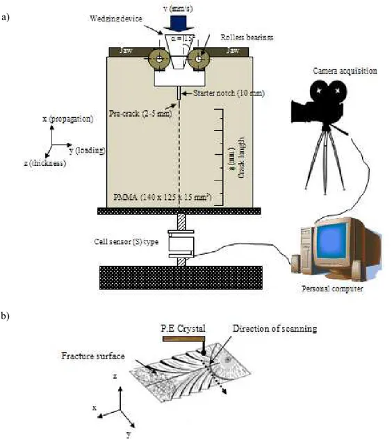
Figure 1: Schematic representation of the experimental apparatus. (a) The wedge-splitting geometry; Principe of applying splitting load and velocity measurements. The dashed line indicates the path of the crack. (b) Surface profile measurements.
A schematic representation of the system studied is shown in figure 1a. The idea consists in pushing a steel wedge in a groove (25 x 25 x 15 mm3) cut of the specimen (140 x 125 x 15 mm3). To minimize friction between wedge and lateral support, two steel jaws equipped with roller bearings are placed between the wedge and the groove. Constant velocity (10-9 to 10-4 m/s) is then applied to the wedge and hence allow to load the specimen in tension. A stable crack is then induced and growth stably and slowly (at a velocity proportional to the wedge velocity) in the specimen, up to the end of this one.
The location of the crack tip as a function of time is determined using a camera Ueye. Image processing gives the position of the crack tip and consequently the instantaneous velocity ν and its variation with crack length. Postmortem analysis of crack surfaces are scanned via a Bruker mechanical profilometer (stylus tip radius 2 µm, out-of-plane resolution 0.1 nm) as shown in figure 1b. Our topographical maps h (x; z) correspond to 14x15 mm2 scans. Each one consists of a series of 999 lines parallel to the front direction Oy, each line containing 324 data points.
a)
Results
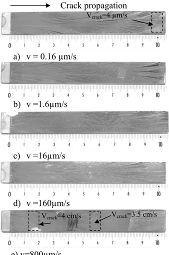
Figure 2 shows the postmortem fracture surface of PMMA for various wedge speeds. Light gold coatings were employed to provide better reflection from the otherwise transparent surfaces.
Crack propagation a) v = 0.16 µm/s b) v =1.6µm/s c) v =16µm/s d) v =160µm/s e) v=800µm/s
Figure 2: Fracture surface of PMMA broken with different cross-head speed v. Light gold coatings were employed to provide better reflection from the otherwise transparent surfaces.
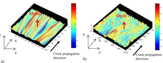
Three distinct patterns can be observed on the post-mortem fracture surfaces: Perfectly smooth, regularly fragmented (Fig.3a) and macroscopically rough (Fig.3b). The observation of one or the other of these patterns depends essentially on the crack velocity. The usual surface fracture pattern of PMMA at crack tip velocity is featureless and smooth to the naked eye, tough sometimes vividly hued. Below a critical velocity Vc ~ 3.5-4 cm/s, we observe a transition from this mirror-smooth
pattern to one with almost regularly spaced fragments (Fig.2e). The two patterns are separated on the fracture surface by an arrest line that suggest important acceleration/deceleration in the crack velocity. As the crack tip velocities continue to decrease and become smaller than 4 µm/s, a second transition is noted and the regularly fragmented fracture pattern becomes a rough one (Fig.2a). As for the first transition, this fractographic change is accompanied by a sudden drop in the crack velocity, from 1.5 10-5 m/s to 4.10-6 m/s, although the wedge speed was maintained constant over the whole fracture test (Fig.4).
Vcrack=4 µm/s
Vcrack=3.5 cm/s
a) b)
Figure 3: Surface fracture pattern realized with the help of a mechanical profilometer 3D (stylus tip radius 2 µm, out-of-plane resolution 0.1 nm) a) Fragmented surface pattern b) Rough surface pattern.
At high crack speeds, the fracture surface becomes rougher with rib marking appearing along the direction of crack propagation. At low speeds, the ribs appear as numerous needle-like markings. They become coarser at high speeds.
a) b)
Figure 4: Measured crack velocity (Vcrack)as function of crack length (c) a) for v = 0.16 µm/s b) for
v = 800 µm/s. Conclusion
We have presented experimental evidence indicating the existence of low speed instabilities in the brittle fracture of PMMA. Three distinct patterns can be observed on the post-mortem fracture surfaces: perfectly smooth, regularly fragmented and macroscopically rough. The transition between these patterns seems to be set by the crack velocity.
Mode I Mode I
Crack propagation
direction Crack propagation direction
z x y z x y
References
[1] B. Lawn, Fracture of Brittle Solids, Cambridge University Press, (1993) [2] L. B. Freund: Dynamic Fracture Mechanics,Cambridge Univ. Press, (1990) [3] K. Ravi-Chandar, Dynamic Fracture, Elsevier, (2004)
[4] D. Hull D Fractography: Observing, Measuring and Interpreting Fracture Surface Topography, Cambridge University Press (1999).
[5] D. Bonamy, J. Phys. D. 42 214014 (2009) (and reference therein)
[6] H.C. Richter and F. Kerkhof, Stress Wave Fractography, In Fractography of Glass, Plenum Press, (1994)
[7] D. Bonamy and K. Ravi-Chandar, Int. J. Frac. 134, 1 (2005)
[8] K. Ravi-Chandar and B. Yang, J. Phys. Mech. Solids 45, 535 (1997)
[9] J. Scheibert, C. Guerra, F. Célarié, D. Dalmas, D. Bonamy, Phys. Rev. Lett. 104, 045501 (2010) [10] J. Fineberg, S.P. Gross, M. Marder, H.L. Swinney, Phys. Rev. Lett. 67 457, 1992
[11] J. Fineberg, M. Marder, Phys. Rep. 313, 2 (1999) [12] M.J. Buehler and H.J. Gao Nature 439 307 (2006) [13] H. Bergkvist, Eng. Fracture Mech. 6, 621 (1974)