Publisher’s version / Version de l'éditeur:
Vous avez des questions? Nous pouvons vous aider. Pour communiquer directement avec un auteur, consultez la
première page de la revue dans laquelle son article a été publié afin de trouver ses coordonnées. Si vous n’arrivez pas à les repérer, communiquez avec nous à [email protected].
Questions? Contact the NRC Publications Archive team at
[email protected]. If you wish to email the authors directly, please see the first page of the publication for their contact information.
https://publications-cnrc.canada.ca/fra/droits
L’accès à ce site Web et l’utilisation de son contenu sont assujettis aux conditions présentées dans le site LISEZ CES CONDITIONS ATTENTIVEMENT AVANT D’UTILISER CE SITE WEB.
Canadian Building Digest, 1967-12
READ THESE TERMS AND CONDITIONS CAREFULLY BEFORE USING THIS WEBSITE.
https://nrc-publications.canada.ca/eng/copyright
NRC Publications Archive Record / Notice des Archives des publications du CNRC :
https://nrc-publications.canada.ca/eng/view/object/?id=0872cc24-edcc-4c39-b4b9-9ed504762492
https://publications-cnrc.canada.ca/fra/voir/objet/?id=0872cc24-edcc-4c39-b4b9-9ed504762492
NRC Publications Archive
Archives des publications du CNRC
For the publisher’s version, please access the DOI link below./ Pour consulter la version de l’éditeur, utilisez le lien DOI ci-dessous.
https://doi.org/10.4224/40000812
Access and use of this website and the material on it are subject to the Terms and Conditions set forth at
Use of sealants
Canadian Building Digest
Division of Building Research, National Research Council Canada
CBD 96
Use of Sealants
Originally published December 1967. G.K. Garden
Please note
This publication is a part of a discontinued series and is archived here as an historical reference. Readers should consult design and regulatory experts for guidance on the applicability of the information to current construction practice.
Some form of seal is required in through-wall joints regardless of the basic principle of the joint design. The success of a joint is greatly influenced by the effectiveness of this seal, but the degree of tightness may be less significant for the control of rain penetration in one system than in another. A seal is intended to prevent the passage of liquids or gases through the space between the two components being joined, despite the differential movements between them. Various systems are being employed in the attempt to achieve the required seal at joints in exterior walls. The most common use elastomeric sealant materials, plastic caulking materials (mastics), or compressed gaskets. This Digest deals with the use of elastomeric sealants, but much of the discussion could apply equally well to other sealant materials.
Elastomeric sealants - marvellous products of modern technology - are viscous liquids that cure to an elastic material with high extensibility and good cohesive and adhesive characteristics, properties that make them suitable for sealing joints in exterior walls. They are installed in the field under a wide variety of conditions, on many different substrates, by persons with varying degrees of interest and ability in performing their jobs. They may, in service, also be subjected to severe deformation or harsh environmental conditions. Accordingly, the design of the joints in which elastomeric sealants are to be employed must be carefully considered. Surface preparation and installation techniques play an important role in sealant performance, but the shape, dimensions and location of the sealant bead are of equal or greater importance.
Shape and Dimension
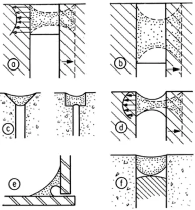
A basic fact, which may not be generally appreciated, is that although the shape of a cured elastomeric sealant can be changed by force, its volume will remain constant. When deformed by a change in joint width, the shape of the cross-section of a sealant bead must change because its area must remain constant. A square bead, when extended, will "neck-in," but in doing so the surfaces free to deform are extended more than the centre of the material so that the adhesion stress at the edges of the bead becomes quite high (Figure 1a).
Figure 1. Sealant Bead Cross-Sections 1. deformation of square bead
2. deformation of deep bead 3. undesirable bead shapes
4. deformation of recommended bead shape 5. corner bead shape
6. bead shape commonly found in joints
W hen the local stress at any point exceeds the adhesion strength, failure commences. It may result in total failure of the adhesion from what should be referred to as a "peeling" action. Because the free surfaces of a deep bead must deform far more than those of a shallow bead, the risk of failure increases with bead depth (Figure 1b). It should also be recognized that if the free surface at either side of the bead is not of sufficient width over-stressing and failure can originate at this surface (Figure 1c).
Study of the deformation of different sealant bead cross-sections indicates that, in general, sealants should adhere only at opposite surfaces and that the free surfaces should be concave. Most of the strain in a bead of this shape (Figure 1d) occurs in its central portion where the cohesive property of elastomeric sealants is generally good. This property can also be
determined in advance. There is a greater area for adhesion with this shape and stresses at the corners of the bead remain relatively low, minimizing the risk of peeling. This basic shape should be used for all sealant heads, including situations where the two surfaces meet at right angles (Figure 1e). Although a sealant bead can seldom tolerate the same percentage strain in compression as in tension, this cross-section improves its potential performance.
The shape factor of sealant beads has been the subject of considerable study and it appears that the best performance can be expected only when a proper shape is employed. It has also been found that the inclusion of air bubbles in the body of a sealant bead should be prevented because they tend to cause a local stress concentration in the sealant. This stress concentration causes a cohesive failure which may propagate down the length of the bead in a "ripping"
action, even without a further change in the joint width. For several reasons it appears that a sealant bead should be wider than the width indicated by the laboratory-determined
extensibility factor and the anticipated movements of the elements being joined. Dimensional variations due to manufacturing and erection inaccuracies, usually discussed under the subject of tolerances, must also be considered when determining the design joint width.
Several conditions must be met to achieve a desirable sealant bead cross-section. The depth of the reglet to receive the sealant must be established by a properly shaped backing of
compressible material to which the sealant will not adhere (e.g. foamed polyethylene rope). This backing must be pinched, attached, or held in some way to prevent its movement under the pressure exerted during installation of the sealant. The sealant must be forced into the reglet so that it fills the intended space completely and is forced into intimate contact with the surfaces to which it is to adhere.
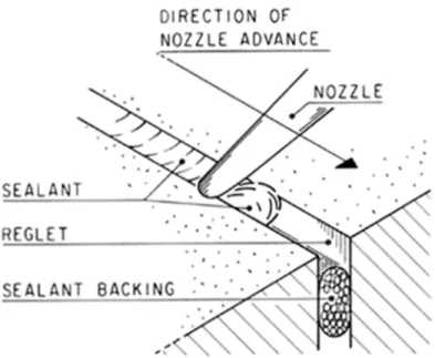
To fill a reglet properly some of the sealant must be forced to flow in the reglet in advance of the gun nozzle (Figure 2). Only when this is done can the fluid sealant be forced to fill the reglet and gain intimate contact with the side surfaces. To produce a concave upper surface, the nozzle tip should be shaped accordingly or the joint surface tooled. The sealant bead shown in Figure 1f is frequently found in joints and is obviously the result of poor installation; it has little chance of successful performance.
Figure 2. Installation of sealant
Adhesion of a sealant is difficult to predict. It depends upon the nature of the substrate, the surface conditions at the time of installation, and the quality of the workmanship, in addition to the properties of the sealant itself. Priming to improve adhesion is essential with some material combinations, and it may be desirable in most instances if only to provide an opportunity for examining the surfaces before installation of the sealant. The sealant manufacturer's
instructions should be followed.
Regardless of its position in a joint, the best performance can only be obtained from a sealant when the bead has the proper shape and dimensions, and when good installation techniques have been employed.
Joint Design
Joints in exterior walls must not permit rain penetration, excessive heat flow, vapour migration or air leakage despite inevitable differential movements between the elements being joined.
Rain penetration can only occur when there is an opening through which the water can pass and a force or combination of forces acting to move it inward (CBD 40). Rain penetration can be prevented if a perfect seal can be achieved and maintained. A perfect seal is not necessary, however, to prevent rain penetration. It can be prevented by designing the joint geometry in such a way that all the forces that can act to drive water inward are controlled. This actually prohibits the use of an air seal at the wetted plane. A seal inward from the wetted plane is necessary, however, to resist air leakage through the joint so that the inward air pressure drop, the major force acting to drive water inward, can be controlled. If the air seal is located where it cannot be wetted, rain penetration will not occur even at minor failures of this seal.
Heat flow at a joint is generally insignificant because of the small area involved unless air leakage occurs. Heat transfer can be reduced by incorporating a dead air space or an insulating material in the joint. The best thermal performance at a joint, however, requires proper design of the edges of the units being joined.
Water vapour migration by diffusion is a slow process and can generally be ignored, especially if there is no exterior seal in the joint. Severe water vapour condensation can occur, however, if humid air is permitted to flow by convection into cold spaces in the joint or to leak through the joint and contact cold surfaces (CBD 72).
Air leakage problems of dirt and odour entry, cold drafts, increased heating and cooling costs, and difficulty in maintaining humidity control can be prevented only by complete air tightness. As this is often impractical, it is fortunate that these problems can be accepted to varying degrees, depending upon the building occupancy. Some interstitial condensation can also be tolerated, depending upon how much there is, where it occurs, the design of the joint, and the materials involved. It is best, naturally, to prevent air leakage as much as possible, since it is instrumental in a majority of wall problems. It should also be mentioned that it is the most difficult mechanism to control.
A study of the requirements of joints shows that the seal in a joint is necessary only for the control of air leakage and that its minor failures can generally be tolerated.
Durability of Sealant
The seal in a joint must provide continuity of the function of the units being joined, not only immediately following installation but also for as long a period as possible, preferably for the life of the building. As with most materials, the properties of elastomeric sealants unfortunately tend to change through time, and this may result in a loss of their ability to perform their required functions. Durability is not an inherent property of any material, but is achieved by protecting it from most of the factors that cause or accelerate its deterioration. The designer who is aware of these factors and of the fundamentals of environmental separation should be able to develop a joint in which deterioration of the sealant is prevented or at least its rate reduced to a minimum.
Sealants located at the exterior of joints are exposed to solar radiation. The ultra-violet radiation and high temperatures that result accelerate the photo, oxidative degradation process. In this position, at the exterior of a joint, sealants must perform in the portion of a wall that is subjected to the greatest range of temperature variation and, consequently, to the greatest differential movements. In cold weather the sealant will be subjected to extreme deformation when it is least able to adjust to movement. The sealant and the materials to which it adheres will be subjected to frequent wetting; and the migration of water to the
interface between substrate and sealant is frequently responsible for severe reduction or loss of adhesion. A sealant bead exposed to view outside or inside is subject to attack by inquisitive fingers and other forms of physical abuse. To provide a long service life a sealant should be protected as much as possible from all these "tortures."
The sealant located toward the interior of a joint is protected from solar radiation, extremes of temperature, and from physical abuse. The sealant bead is only required to resist air leakage if rain water does not contact it. When air leakage is controlled by the part of a wall inward of the
thermal insulation, the differential movements at the air seal in the joint will be at an absolute minimum. Moisture accumulation at the seal from condensation should be prevented by adequate thermal performance of the wall and joints.
Sealants located at the interior can be installed from inside the building and work can proceed despite the erection of panels on floors above. They can also be installed under weather conditions that might prohibit sealing at the exterior. The difficulty of installing sealants in joints located behind columns, beams and floor edges must not, however, be overlooked during design. It is not essential that sealant installation be performed from the building interior, but it is essential that the sealant be located at a reasonable distance behind the exterior surface. A sealant can be protected from the major factors influencing its deterioration when it is located toward the interior side of the joint.
Conclusion
The best joint performance can only be achieved by consideration of all the subjects relating to joints. A successful joint is a compromise based on a thorough analysis of the factors
influencing its performance. It is even possible for an inexpensive material properly used to give service far superior to that of the best material improperly used. The best performance from any sealant and the total joint can be gained by following these simple rules:
1. Design the joint so that the seal is located where it will have the least critical function to perform.
2. Design to protect the sealant from factors that may cause or accelerate its deterioration. 3. Determine the magnitude and nature of the differential movements that will occur at the joint. 4. Select the sealant and design its bead cross section and dimensions in accordance with its
properties and the conditions to which it will be subjected, and ensure that it is properly installed.