Complex Fluids and Hydraulic Fracturing
The MIT Faculty has made this article openly available. Please share how this access benefits you. Your story matters.Citation Barbati, Alexander C., Jean Desroches, Agathe Robisson, and Gareth H. McKinley. “Complex Fluids and Hydraulic Fracturing.” Annual Review of Chemical and Biomolecular Engineering 7, no. 1 (June 7, 2016): 415–453.
As Published http://dx.doi.org/10.1146/annurev-chembioeng-080615-033630
Publisher Annual Reviews
Version Original manuscript
Citable link http://hdl.handle.net/1721.1/107783
Terms of Use Creative Commons Attribution-Noncommercial-Share Alike Detailed Terms http://creativecommons.org/licenses/by-nc-sa/4.0/
Annu. Rev. Chem. Biomol. Eng. 2016. 7:X--X doi: PLEASE INSERT CORRECT CHAPTER DOI, BOTH HERE AND AS TAGGED STRING
Copyright © 2016 by Annual Reviews. All rights reserved
BARBATI MCKINLEY
COMPLEX FLUIDS & HYDRAULIC FRACTURING
C
OMPLEX
F
LUIDS AND
H
YDRAULIC
F
RACTURING
Alexander C. Barbati,
1Jean Desroches,
2Agathe Robisson,
3and
Gareth H. McKinley
11
Hatsopoulos Microfluids Laboratory, Department of Mechanical Engineering, Massachusetts Institute of Technology, Cambridge, Massachusetts 02139 email missing
2
Schlumberger, Paris la Défense 92936, France
3
Schlumberger-Doll Research, Cambridge, Massachusetts 02139
Abstract Nearly 70 years old, hydraulic fracturing is a core technique for stimulating hydrocarbon production in a majority of oil and gas reservoirs. Complex fluids are implemented in nearly every step of the fracturing process, most significantly to generate and sustain fractures, and transport and distribute proppant particles during and following fluid injection. An extremely wide range of complex fluids are used: naturally occurring polysaccharide and synthetic polymer solutions, aqueous physical and chemical gels, organic gels, micellar surfactant solutions, emulsions, and foams. These fluids are loaded over a wide range of concentration with particles of varying size, and aspect ratio, and are subjected to a extreme mechanical and environmental conditions. We describe the settings of hydraulic fracturing (framed by geology), fracturing mechanics and physics, and the critical role that non-Newtonian fluid dynamics and complex fluids plays in the hydraulic fracturing process.
Keywords hydraulic fracturing, porous media, rheology, complex fluids, suspension mechanics, particulate transport
1. INTRODUCTION
Hydrocarbons are crucial feedstocks across all sectors of the global economy. The ease of hydrocarbon extraction translates directly into petroleum availability and lower cost for products derived from petrochemicals. Periods of increased worldwide demand, coupled with restricted supply of hydrocarbons, have
encouraged and enabled various technological advances to recover oil and gas that is increasingly difficult to remove from the ground. While a variety of reservoir stimulation techniques are currently used, we describe the process of hydraulic fracturing and the central role that particulate transport by complex fluids plays through it.
Although hydraulic fracturing of source rocks (also loosely called “shales”) - as opposed to hydrocarbon reservoirs - is a topic of contemporary (and often contentious (2)) interest, hydraulic fracturing is used in a majority of oil and gas reservoirs at some point in their lifetime. Fracturing is used in conventional hydrocarbon reservoirs to increase permeability in damaged formations or in formations which exhibit significantly lower production rates over what could be achieved after fracturing stimulation. It is also used in reservoirs where the intrinsic permeability is too low to yield economical production without it.
Reservoir stimulation by hydraulic fracturing creates reservoir surface by pumping a particle-laden fluid into the rock, generating a large pressure relative to the hydrostatic pressure downhole. Since the rock has low permeability, and the fluid is (mostly) incompressible, the growing pressure is relieved by the fracturing of reservoir rock generating a new flow path. Pumping stops when the desired volume (and fracture extensions) is attained or when the pressure
required to sustain fracture growth exceeds the available pumping capacity; at this point the well is shut. Over time, the pressure in the fracture and in the formation will equilibrate, following the penetration of the injected fluid into the formation and the closure of the fracture. This process depends largely on the fluid leak-off rate inside the formation, and can take several days in low permeability formations. The fractures do not close completely, as the sand or other proppant carried into the fracture by fluid transport remains, and will prop the fractures open. Following this shut-in and leak-off period, the well is
reopened and liquid or gaseous hydrocarbons flow out into the well from which they can be extracted or produced.
The hydraulic fracturing process depends critically upon complex fluids. Prior to hydraulic fracturing, a well must be drilled , cased and cemented. Drilling muds (either aqueous or oil-based) are employed as mechanical stabilizers in the construction of the wellbore to pressurize (via gravitational hydrostatic pressure) the sidewall against collapse, cool the drill bit, and carry away rock cuttings.
Cements are pumped downhole to form a reinforced casing and (along with metal pipe) isolate sections of the wellbore, providing crucial isolation (1) of the well from the surrounding environment. The first step of fracturing consists of pumping a solid-free fluid, called a pad, that initiates the fracture prior to the introduction of a particle-laden fracturing fluid. This way, risks associated with particles reaching the tip of the fracture (described in Section 4) are mitigated.
The fracturing fluids used in commercial operations are proprietary
formulations specific to the geology of the formation and desired treatment, yet nearly all contain rigid proppant particles used to hold the newly-generated fracture network open after the cessation of flow. Fluids ranging from dilute polymer solutions (i.e., ‘slickwater’), polysaccharide solutions (crosslinked and linear), foams (also called energized fluids), micellar fluids (viscoelastic
surfactants), and oil-based fluids are loaded with particles of varying size, aspect ratio, and density to achieve the desired combination of chemical and mechanical properties.
Fluid selection for hydraulic fracturing is a design problem. Optimality is economic: given a hydrocarbon reservoir with a specific set of geological characteristics, what set of fluid properties will produce the most hydrocarbon for the least cost? This question is straightforward but nontrivial, as it requires a thorough understanding of (i) the petrophysical properties of the hydrocarbon reservoir, (ii) the rheology and formulation costs of the particle-laden complex fluid used in fracturing, (iii) the fluid--solid interaction driving the hydraulically-induced fractures in the anisotropic hydrocarbon reservoir, and (iv)
quantification of risk--reward since no process is 100% reliable. The industry has turned to complex fluids to satisfy this optimization process.
In this review, we focus on the application of complex fluids and
non-Newtonian hydrodynamics which governs the hydraulic fracturing of oil and gas reservoirs. This necessarily requires an understanding of hydrocarbon reservoirs, with particular attention to the fluid--solid interactions that occur during the fracturing process, and the nature of reservoir rock (and bounding layers) in general. We first consider a brief history of hydraulic fracturing. This is followed by a discussion of hydrocarbon reservoir petrology and geomechanics. Then, we consider the mechanics of hydraulic fracturing, focusing on the role of fluid, reservoir, and flow properties in determining the fracture geometry. Finally, with
the fracturing process quantitatively described, we detail the rheology of complex fluids relevant in the oilfield and explore the wide-ranging and varied types of fracturing fluids that are employed downhole, highlighting the various processes that these complex fluids are involved in during the hydraulic
fracturing process, as well as the potential knowledge gaps associated with them. 1.1. A Brief History of Hydraulic Fracturing
Hydraulic fracturing is the progeny of reservoir acidizing processes that date back to the late 1800s (3). Acidizing increases permeability and production in reservoirs through the injection of acids directly into the formation which react with, and subsequently dissolve, carbonates and some sandstones (4, 5). The Van Dyke acidizing patent (3) describes several of the features present in fracturing today: the use of a rubber packer to isolate target areas of the well, the loading of the well with a target fluid (in this case an acid), the pressurization (via an imposed hydrostatic head) of the fluid to improve penetration into the formation, and then the breaking (in this case neutralization) of the fluid with a base. This technique was later expanded upon by Grebe and Stoesser (6) who describe an “organic jellifying material” for use in wells. Grebe and Stoesser further describe a wide range of fluids and fluid-property modifiers in a 1935 article (7), and also a description of the hydraulic rock-splitting action (Figure 1) to increase the effectiveness of acidizing. All of these technologies have descendants in the modern oilfield. Hydraulically-driven reservoir deformation was further
recognized in water injection and cementing operations throughout the 1940s, as summarized in the monograph by Howard and Fast (8).
<COMP: PLEASE INSERT FIGURE 1 HERE>
Figure 1 Then and now. Upper left: Schematic diagram of fracturing during an acidizing treatment ca. 1935, from product literature (7). Upper right: The first fracturing operation (1947) in Grant County, Kansas (courtesy Michael B. Smith, credit: Robert C. Fast). Lower left: schematic diagram of a contemporary fracturing job (courtesy Schlumberger) Lower right: Layout for a contemporary fracturing operation. Pump trucks are arrayed at center, and outlying trailers contain liquids. (©CustomAerialImages.com).
The first hydraulic fracturing operation occurred in the Hugoton field, Kansas in 1947, where a gelled gasoline was used as the fracturing fluid. In the decades since, hydraulic fracturing has grown in scale and importance, following
steer a drill bit horizontally over long distances, it enabled the production of source rocks that were not considered produceable previously. In the United States alone, it is estimated that 986,000 wells received fracturing treatments between 1947 and 2010 (9); 278,000 of these wells, mostly focused on the development of source rocks, have been drilled since the year 2000. One reason for this uptick are the increased lateral distances that can be drilled;
contemporary wells routinely exhibit horizontal laterals (l ) in excess of one h mile (10--12). Operators are presently pursuing lengths in excess of 2.25 miles (13). The increase in length is enabled by a decrease in cost per length drilled, which has fallen 57% in the past 4 years (10), current costs (2015) being about 1000$/ft, more (wet) or less (dry) depending on the produced fluid. Fractures are introduced along these laterals by injecting liquids at high flowrate (in excess of 90 bbl/min (14)), stimulating ever-increasing reservoir volumes from isolated wells, recently termed ‘super fracking’ (15).
bbl/min: Common rate of flow in the oilfield, equivalent to 0.111 m3 s−1. 1 bbl is equivalent to 42 gallons
1.2. Requirements for a hydraulic fracturing fluid
The demands on a hydraulic fracturing fluid are many, and will be briefly mentioned here, from the sourcing of the material all the way to the cleanup of the fracture after the treatment has stopped. The material for the base fluid should be inexpensive, easy to source, of constant quality and harmless environmentally. It should be easy to mix on the fly and to pump, and should exhibit a low friction pressure in a pipe in turbulent regime, as it goes down the wellbore. When it hits the perforations in front of the rock to be stimulated, it should transport proppant through these perforations, which make a 90 degree angle with the direction of the flow. After going through the perforations, which behave like jets, it should recover viscosity thinned in the high-shear perforation to create fracture width. It should suspend proppant both in dynamic and static conditions, and exhibit low leakoff into the formation. After pumping has stopped, it should allow the fracture to close quickly and prevent proppant from settling. After the fracture has closed, it should flow back to the surface easily, without impairing the flow of hydrocarbons either through the matrix where it had previously leaked off or through the proppant pack. Finally, its properties
should be tunable to a wide range of downhole temperatures and chemical environments.
Let us note that, for simple Newtonian fluids, many of those requirements are contradictory in nature, e.g. the low friction pressure in the pipe and the high pressure drop in the fracture, or the proppant suspending capability and the ease of proppant pack cleanup. This is the main reason why the industry has turned to the complex fluids to satisfy these requirements.
2. HYDROCARBON RESERVOIR PETROLOGY
Sedimentary rocks form the majority of oil reservoirs. Sedimentary rocks can be formed by the successive deposition of fluids and minerals from weathering (mechanical and chemical), evaporation, or biogenic activity, which, over time, become continuous and porous structures such as sandstones, limestones, and mudstones (16, 17). We shall omit evaporites as they tend to have no porosity or permeability. This sedimentation process occurs as a set of discrete depositions, and the rock is formed by a combination of compaction and cementation (17). Sedimentary reservoirs are porous and present many distinct and identifiable layers, with the precise nature of the sedimentary rock determined by the depositional environment (e.g. a marine shale versus an aolian dune set), along with the thermodynamic and mechanical history of the reservoir as a whole. The size, shape and topology of sedimentary structures, along with the
thermo-mechanical properties exhibited locally in the lithosphere, determine many of the pertinent reservoir properties for hydrocarbon production (18).
Kerogen: A nanoporous (19) material, insoluble to both alkaline and organic solvents.
In some sediments, interspersed among clay, sand, and silt are organic materials that will degrade to form oil and gas. Organics trapped within the sedimentary rock experience progressively greater temperatures (increasing at a rate of about 2.5°C/100m (20, 21)) and stresses as the layers travel deeper into the earth (21). The gradual degradation of organics in these source rocks occurs in three stages: diagenesis, catagenesis, and metagenesis; they can be loosely thought of as the ‘heating’, ‘cooking’, and ‘burning’ of organic material.
of several hundred meters; Here, organic matter is converted to kerogen (21, 22). Kerogen is acknowledged to exist in three types, delineated by origin, structure (aliphatic versus polyaromatic), and constitution (atomic ratios of hydrogen to carbon and oxygen to carbon (21, 23, 24)). Oil and gas molecules are derived from kerogen during catagenesis, which occurs at temperatures between 50 and 150°C. Gas is generated primarily at the higher end of this window. Organic material subjected to yet greater temperatures continue to degrade into dry gas (i.e., methane), with carbon as the ultimate endpoint of thermolysis.
While kerogen is converted to oil and gas in such formations called “source rocks”, traditional drilling operations do not extract hydrocarbons directly from them, as the volume concentration of hydrocarbon is low. Hydrocarbons may undergo primary migration, exiting the source rocks where they originated and then undergo secondary, buoyancy-driven, migration to and within distal porous layers. Eventually, further upward motion of the hydrocarbons is arrested by an impermeable cap (16) and oil and gas sit bounded. Conventional extraction targets oil and gas away from source rocks, in these secondary porous structures where hydrocarbons are concentrated.
The most economically favorable reservoirs exhibit large porosities and permeabilities. Porosity, hydrocarbon saturation and reservoir volume set the available amount of hydrocarbons to be extracted, while reservoir permeability sets the relative ease by which the hydrocarbons may be removed. Early oil and gas drilling relied upon the pressure in the earth to expel hydrocarbons directly or with minimal pumping from the wells (primary recovery). If the hydrocarbons are liquid, this production technique produces only a minimal amount of the hydrocarbons in place and other methods have been developed to recover more of them. For example, as the pressure in the reservoir will decrease as
hydrocarbons are produced at the surface, positive displacement of water can then be used to drive hydrocarbons to the surface, known as secondary recovery. Finally, enhanced oil recovery (or tertiary recovery) makes use of chemical additives pumped downhole to coax and recover oil that could not be removed in earlier stages. In all cases, the techniques used are determined by the
hydrocarbon content and flow properties of the reservoir --- multiple techniques may be used on the same reservoir over the course of its lifetime.
2.1. Fluid Flows in Reservoir Rocks
The sedimentary process endows reservoirs with widely varying porosity and permeability (18, 25--27). The initial sedimentation of material forms a porous structure which, through time, is acted upon by chemical and mechanical forces (28--30) to provide (i) pores in organic material, (ii) pores in inorganic material, and (iii) faults and fractures (31--33); all processes and features yield widely variable porosity and permeability within the reservoir (18, 25--27).
Additionally, the sediment settling process results in anisotropic permeabilities such that transport is favored along the sedimentary beds rather than the direction of deposition (18).
Inorganic (i.e., mineral-based) and organic (i.e., kerogen-based) pores in mature source rocks are discussed in detail by Bernard and Horsfield (34), highlighting the change in morphology of the pore network as the source rocks age. Source rocks are distinguished from conventional oil reservoirs by reduced pore size (35) and the role of nanoscale pores within kerogen trapped in the rock. Nanoscale pores in kerogen may not form a formation-spanning connected network, but do form a local network on the scale of the organic deposit and are storage sites for gas (19, 30).
Many porous media flows are well-described by Darcy’s law, ij i j k p u x η ∂ 〈 〉 = − ∂ 1.
Here, u is the local velocity of the pore fluid, and the brackets, 〈〉, indicate that this velocity is an averaged quantity. This velocity is proportional to the pressure gradient across the porous media via a permeability tensor, kij, and a fluid viscosity η. The
quality or ‘goodness’ of reservoirs is often quantified using permeability values, along with the porosity and total amount of organics available for extraction in the reservoir. Bear (36) (his Table 5.5.1) tabulates permeabilities for soils and rocks. Notably,
4
10≤ ≤k 10 mD for ‘oil rocks’, 10−1≤ ≤k 10 mD for sandstone, and k ≤ mD is 1
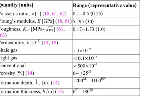
listed as ‘impermeable’, or ‘tight’ in contemporary parlance (18). Modern production technology has significantly modified what we consider as impermeable, see Table 1
for more contemporary values and classification. <COMP: PLEASE INSERT TABLE 1 HERE>
Permeability: A geometric constant of a porous material indicating resistance to flow. It incorporates both the porosity and the tortuosity of the porous media. Porosity: A measure of the open space in a material, reported as percent of void space.
Darcy: Permeability carries units of length squared, and is typically cited in Darcies, 1 D = 9.867 × 10⁻¹³ m2; milli- and nanodarcy permeabilities are
commonly reported.
The linear Darcy relation generally holds for creeping flows of Newtonian fluids. Corrections exist to accommodate larger Reynolds number flows (37), large-scale velocity gradients (38), non-Newtonian effects (39--41), and
pressure-dependent permeabilities (25, 37). Despite these corrections, departures from strictly Darcian flow conditions remain an open problem. Complications arise in time-dependent processes, like hydraulic fracturing, where the
permeability may vary owing to components adsorbed onto the porous matrix from the fluid, and/or variations in the pressure difference between the matrix and fluid modulating the pore structure.
The Darcy law (Equation 1) is invalid for gas flows in nanopores such as those found in kerogen. For these flows, the mean free path (λ) of gas within the pores is large as compared to a characteristic diameter of the pores, dp, and the
continuum Darcy law is strictly inapplicable. The ratio of these lengths form the Knudsen number, Kn
P dλ
= , revealing if the flow may be described using classical continuum descriptions of transport (Kn= 1), if slip effects must be included (10−3 ≤Kn 10≤ −1), or if free-molecule flow (Kn 10≥ 1) must be used to
describe gas transport. Several models have been proposed (42--44), starting with the Klinkenberg relation (42) which introduced an empirical permeability,
ks, slip ‘corrected’ to augment the permeability in the Darcy law,
(1 / )
s b
k =k∞ +K p , so that decreases in thermodynamic pressure (p) will
augment the permeability; here, k∞ is a liquid permeability in the same medium,
p is the pressure in the pores, and Kb is the Klingenberg constant.
There is no universal relation to connect the porosity, φ, to the permeability kij
in rocks or porous media in general. This failure arises from the inherent dependence of the permeability on the detailed geometry of the pores, and the distribution of pore sizes, whereas the porosity is a scalar measure that does not
include pore-scale information beyond the volume fraction of solids. Strikingly, the permeability in mudstones can vary over three orders of magnitude for the same value of porosity (27)! Despite this limitation, several empirical
correlations and analytical models exist (27, 37); The success of the various models depends upon how well the underlying assumptions match physical characteristics of the targeted reservoirs. Katz and Thompson, recognizing the self-similarity of pore spaces for several sandstones (45), developed a predictive permeability model (46) k c= lc
σ σ
/ 0, where c is a numeric constant, l is a c length scale from mercury injection measurements, and G and Gc are electricalconductivities of the brine saturated porous media and brine, respectively. The Katz and Thompson model includes two important components: (i) a single characteristic length, l , which dominates momentum transport, determined by c the inflection point of pressure during a mercury injection test (37), and (ii) a measure of the pore connectivity through the independent electrical conductivity measurements of brine.
Brine: A salt solution typically at a concentration greater than seawater.
Concentrated salt solutions suppress surface conductance effects and encourage measurement of solution conductance.
Natural fractures can also contribute to the porosity and permeability. Fractures in rocks form from stresses and natural fluid motion. These fractures and associated fracture networks have been identified as major contributors to shale gas reservoirs (47--49); it is therefore desirable in these systems to intersect the natural fracture network during the drilling and hydraulic fracturing process (50). Natural fractures are characterized by orientation, length, aperture, and roughness (33, 49, 51, 52). Similar to the porous media described above, the natural fracture network can exist in a percolated or unpercolated state, and can also be both anisotropic and heterogeneous (51). Percolated fractures within hydrocarbon reservoirs do not necessarily conduct liquids or gases; the fractures may be filled with calcite, or are otherwise sealed (48, 50). Transport models for fractures and fracture networks suffer similar limitations to the porous media discussed previously -- the geometry of the networks and individual fractures is strongly variable and typically unknown. Despite these uncertainties, individual
fractures (53) and fracture networks in porous matrices (52, 54--56) have been analyzed to elucidate estimated flows and permeabilities for Darcy flows.
Despite all complications associated with the description of multiphase flow in rocks (brine, liquid and gaseous hydrocarbons), one can infer that the total flux that can be drained from a reservoir into a well is a function of the rock
permeability, viscosity of the reservoir fluids, pressure gradient and surface area over which that pressure gradient is applied. Rock permeability is provided by geology and can only be altered locally (e.g. by the injection of reactive fluids). Mobility of the flowing fluid(s) is also given by the nature of the fluids in place and the temperature and pressure conditions in the reservoir– even if it can be modified in some cases by heat (e.g. injection of steam) or injection of
surfactants. The amount of pressure gradient that can be applied is also limited, roughly by the difference between the initial fluid pressure of the reservoir and the weight of the hydrostatic column in the wellbore. It is therefore natural to look at the surface area over which a pressure gradient can be applied from the well to the reservoir.
A vertical well drilled in a hydrocarbon reservoir drains the reservoir fluids through a small contact area with the producing layers: the intersection of a 0.2m diameter well with a 15m thick producing layer results in about 20m2 of contact area. The magnitude of this contact area can be increased if the well is drilled with a long portion following the producing layer: a 1000m lateral drain placed in the same producing layer would have a contact area with the reservoir of about 1,250m2. Another means is hydraulic fracturing, whose goal is to create a large surface area in contact with the reservoir. For example, the creation of a 100m long bi-wing fracture in contact with the same reservoir would result in a contact area of 3,000m2. If the permeability of the fracture is large enough so that the pressure in the fracture is close to that in the wellbore, hydraulic fracturing is extremely effective at promoting flow from low permeability reservoirs. One of the goals of hydraulic fracturing is thus to create a fracture whose permeability is infinitely large compared to that of the reservoir that it is draining. Let us remark, finally, that for reservoirs with extremely poor flow characteristics (e.g. with permeabilities of the order of 100nD or less), lateral drains can be hydraulically fractured to create enough drainage area to concentrate enough flow into the wellbore.
2.2. Mechanical Attributes of Rocks
Hydraulic fractures arise from fluid--solid interaction resulting in mechanical failure of the formation. The orientation, geometry and extent of these fractures depends strongly on the intrinsic mechanical properties and state of stress of the reservoir rock. As one wishes to limit the extension of the created hydraulic fracture to the producing layers of interest as well as extending the fracture as long as required to obtain the desired producing area, a brief description of the mechanical system formed by both reservoir rocks and the layers adjacent to them follows. Reservoir rocks are usually modeled as linear elastic materials. This is not strictly true for rocks in general (18); elevated temperatures and the presence of pore fluid can lead to plastic rather than elastic failure (57, 58). However, for the hydraulic fracturing process, this has proved extremely
effective, mostly because of the loading path followed by the material during the fracturing process.
Within the linear elastic framework, reservoir rocks are characterized by a modulus of elasticity, E, and Poisson’s ratio, ν. Note that anisotropy of the rock can also be taken into account. Measurements of these properties can be
performed on drill cores removed from the earth, although the cost can be prohibitive and care must be taken to preserve the in situ rock conditions (water/fluid content, overburden pressure) when tests are performed (58). Sonic logging tools permit direct interrogation of rocks downhole (59), accomplished by measuring the propagation speed of waves through rock and using the density to recover elastic moduli and Poisson’s ratio. These and other dynamic methods typically yield larger values of both the Poisson ratio (60) and elastic moduli (60,
61) as compared to measurements using static methods, as would be done in the lab on core samples in gradual compression. Correlations have been developed to allow the transformation of the parameters obtained under small strain / large frequency (dynamic) conditions to parameters corresponding to large strain / low frequency (static) conditions required for modeling the hydraulic fracturing process. Beyond variations in these values due to test type and configuration, mechanical properties also vary substantially from reservoir to reservoir and
within rock layers forming the reservoirs, as presented in Table 1, and in the references cited therein.
Tensile failure in rocks can be characterized by a fracture tougness
K
IC. Contrary to the variation in the elastic parameters, the value of the fracture toughness does not vary strongly between rocks and is of the order of 1MPa m.
The lithostatic stress determines the orientation and, along with rock properties and the injection pressure, the extent to which the reservoir may be fractured. Lithostatic stresses can be highly anisotropic. These stresses arise chiefly from the weight of rock atop any given point in the reservoir. Typically, the lithostatic stress is highest in the vertical direction (aligned with gravity), with a horizontal stress that varies as a function of depth. Brown and Hoek (64) tabulate the ratio v
h
r= and write the empirical bounds σσ 100 0.3 1500 0.5
z + ≤ ≤r z + ,
where z is the vertical depth in meters. Because the density of rocks is not a strongly varying quantity, the vertical stress at the same vertical depth z correlates with 27 103
v z
σ = × , with
σ
v in Pascals. Complexities arise due to the superposition to gravity of both tectonic activity, thermal and fluid pressure effects on the potentially complex geological structure hosting the reservoir of interest.2.3. Designing around geological constraints
In order for a hydraulic fracturing treatment to be effective, one wants to create a hydraulic path that is localized to the producing layer targeted,
perpendicular to the bedding of that layer (to take advantage of the permeability anisotropy of reservoir rocks). Note that, if the minimum principal stress is vertical, the reservoir is unfit for hydraulic fracturing as horizontal fractures will be favored, which will not drain the reservoir effectively. That hydraulic path should also extend sufficiently away from the wellbore and be of an infinite conductivity compared to that of the targeted layer.
Creating a hydraulic fracture of a desired geometry by designing around the geological constraints is only the first step to attain these objectives. One also needs to ensure that there is enough residual permeability of the hydraulic
fracture once pressure is decreased to start flow from the reservoir. This is achieved by placing solid particles that form a highly permeable layer inside the fracture (proppant pack). Transport of these particles from surface to the fracture, so that a permeable enough pack is formed in front of the target layer, is
therefore a critical aspect of hydraulic fracturing. Using fluids that do not damage the flow capacity of the reservoir or that of the proppant pack is also of high importance.
Finally, the - possibly large - variations of both mechanical and flow properties from one layer to the next, along with often poorly constrained variations of these properties along a layer, 100m away or more from the wellbore, put a very strong requirement of robustness on the design of a hydraulic fracture to such variations, and thus on the fluid systems that will be used to create them.
3. MECHANICS OF HYDRAULIC FRACTURING
The mechanics of fracture generation and arrest have been extensively studied in the decades following the first field tests. Since the choice of fluid and pumping rate are the main design levers to achieve the desired fracture geometry in a given geological setting, these studies have highlighted the - often conflicting - requirements placed on hydraulic fracturing fluids. In the following section, we review the phenomena specific to the fluid-solid interactions in hydraulic fracturing.
3.1. Fracture Orientation and Geometry
The fracture orientation conspires with the flow properties of the reservoir rock to determine the efficacy of the fracturing operation. Reservoirs have anisotropic permeability. The permeability is generally smallest through the plane of
bedding, thus the desired flow path is perpendicular to the formation bedding. The orientation of hydraulic fractures is predominantly controlled by the in situ stresses of the reservoir (61, 89), and fractures tend to open in the direction of the minimum compressive stress. This was clearly demonstrated in a set of
laboratory experiments by Hubbert and Willis (90), using a gelatin mold as the reservoir and liquid plaster as the fracturing fluid; after curing of the plaster, fractures of vertical and horizontal orientation were observed consistent with
compressive stresses applied to the mold. A study of the rank ordering of the stresses in the reservoir is thus a pre-requisite to decide if hydraulic fracturing can be applied or not. If the minimum stress is near perpendicular to the reservoir bedding, a hydraulic fracture parallel to bedding will be created regardless of the fluids being used. Thus, flow on the fracture face proceeds through the direction of minimal permeability, limiting the benefit of the fracturing process to increase production.
Pre-existing fractures, joints, and faults can, however, redirect or modify the propagation direction of induced fractures (89, 91--94). In conventional
reservoirs, this reorienting effect is not generally strong enough to override the global fracture orientation that is dictated by lithostatic stresses (95). In
unconventional reservoirs (often fractured source rocks), the interaction between the hydraulic fracture, the bedding planes, and the pre-existing fractures and faults has tremendous importance, directly impacting the amount of stimulated reservoir area. Whether a hydraulic fracture ignores a pre-existing fracture / bedding plane is not only a function of the geomechanical setting but also of the fracturing fluid (Yew2014), which adds another dimension to the selection of fracturing fluids.
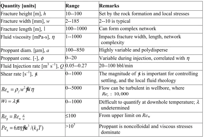
Measurement of hydraulic fracture geometry is challenging, requiring remote downhole, or direct measurement from mineback experiments (95). A wide range of fracture lengths, widths, and heights are reported in the petroleum literature, and, along with treatment and reservoir parameters (50), are highly variable (96, 97); see Tables 1 and 4 for ranges of natural and engineered parameters.
Mineback: Excavation of a fractured formation to measure fracture geometry and extent.
<COMP: PLEASE INSERT TABLE 4 HERE>
The width of the fracture is the smallest lengthscale in the system; It is largest at the wellbore, where the pressure is greatest, and decreases towards the fracture tip. Cipolla et al. (97), in a discussion on the relation between fracture
complexity and dimension, provide fracture widths varying from 2.5 mm to 185 mm when fluids ranging from waterfrac/slickwater (basically dilute polymer
solutions with η ∼O(1) mPa-s) to gel-like fluids (η ∼ O(100 –1000) mPa-s) are used. The fracture length is typically hundreds to more than a thousand meters, and the fracture height may be 50--100 m. The flow may branch during
stimulation, forming a tortuous network of fractures. Treatments of the same reservoir with different viscosity fluids have been observed to follow the general expectation that lower viscosity fluids produce longer (and thinner) fractures than thicker gel-based systems (97). The impact of multiple fracture treatments staged along a horizontal wellbore can be inferred from microseismic
measurements (98), where the seismic activity is assumed to coincide with fracture progress.
3.2. SIMPLE MODELS FOR HYDRAULIC FRACTURE GEOMETRY
One of the strong peculiarities of hydraulic fracturing is the robust coupling between fluid flow, reservoir deformation, and fracture growth. We discuss here insights provided by the two-dimensional Perkins-Kern-Nordgren (PKN) and radial and Kristianovic-Geertsma-de Klerk (KGD) models. These models are physical and geometrical simplifications of the full transient and
three-dimensional fluid--structure interaction problem. These approaches, following a variety of assumptions, provide analytical solutions to the fracture problem illustrating the dominance of dissipation mechanisms and how these mechanisms translate to fracture geometry and fluid design. Regardless of their simplifying assumptions, these models are used to validate hydraulic fracture simulations (65) and inform fracturing job design where applicable.
3.2.1.PK,PKN,KGD, AND RADIAL FRACTURE MODELS
Models by Perkins and Kern (66) (PK), later modified by Nordgren (67) (PKN), a plane-strain model by Kristianovic (68), Geertsma and de Klerk (69) (KGD), along with a radial model (69, 70) all present simplifying assumptions in the state of strain and dissipation, many of which been revisited in later
refinements.
In the PKN model, a bi-wing fracture with elliptic cross-section emanates from the wellbore. The height (ellipse major axis) of the fracture is set a priori by the height, h, of the formation. bounded by layers that are known to (by experience)
arrest vertical fracture growth. The fracture width, w, (ellipse minor axis) is determined via a plane strain elasticity relation (71):
2
(1
)
( , ) 2
( ( , )
)
w x t
h
p x t
E
ν
σ
⊥−
=
−
2.Here, the pressure in the invading fluid, p(x, t), balances against the far--field solid stress, σ⊥, in the formation and compression of the linear elastic reservoir with Poisson’s ratio ν and Young’s modulus E. Note that only the difference is significant, Δ =p p x t( , )−σ⊥. The plane strain condition in each vertical plane constitutes a crucial simplifying assumption --- the elliptical deformation profiles in the direction of the fracture propagation become uncoupled. Whence, the fracture width (minor ellipse axis) is determined uniquely by the local fluid pressure, reservoir stress, Young’s modulus, and Poisson’s ratio at each location along the fracture. Furthermore, in this model, fracture behavior at the
propagating tip is completely neglected; the fracture toughness does not appear in the solution.
The pressure in the fluid is given by a lubrication approximation to the Navier-Stokes equations, inherently assuming laminar flow prevails. Here, the pressure drop along the fracture depends linearly on the viscosity, η, and flow rate, while depending more strongly on the fracture width, so that,
3 64 p Q x w h η π ∂Δ = − ∂ 3.
Note that the flowrate in the fracture, Q, and the width, w, are functions of
position and time. The flowrate varies in time and space along the fracture by any combination of (i) a change in pumping rate (or ‘flow schedule’) at the surface, (ii) leak-off of fluid through the porous fracture walls into the formation, and (iii) accumulation in the fracture as the width varies in space and time.
A statement of mass conservation connects the fracture width (Equation 2), pressure drop (Equation 3), flow schedule, and other system properties to enable prediction of fracture geometry as a function of time:
0 4 L Q q h w x t π ∂ + + ∂ = ∂ ∂ 4.
The first term accounts for the change in volumetric flow as a function of
position along the fracture, the second term, qL is the volumetric flowrate of
leak-off per unit fracture length from the fracture into the formation, and the final term accounts for the expansion or contraction of the fracture width as a function of time.
The early work by Perkins and Kern (PK) (citation) assumed ∂∂Qx
=
0
, neglecting both changes in fracture area and leak-off. Nordgren (citation) recognized that both leak-off and evolution of the fracture aperture must be included, resulting in a nonlinear partial differential equation for the fracture width: 2 4 2 2 1 1 4 1 ( ) 0 128 1 L E w w q h x h xη ν
∂π
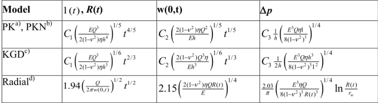
∂ − + + = − ∂ ∂ 5.This equation is subject to the initial condition w(x, 0) = 0, and the distal boundary condition w(x, t) = 0 when the coordinatex≥ l( )t , where l( )t is the fracture length at arbitrary time. The problem is closed by an additional boundary condition on the flow into the fracture as a function of time: Q(0, )t = Γ( )t . In the absence of leak-off, the fracture length, width, and pressure difference in the fracture have all been determined analytically for a constant injection rate at the wellbore (72). These results are shown in Table 2. Note that this model
corresponds to the limiting case of a height-constrained fracture with a length much larger than the height.
<COMP: PLEASE INSERT TABLE 2 HERE>
Models for other limiting cases include that of Geertsma and de Klerk (69), incorporating work from Kristianovich (68), who developed models that include the influence of the fracture tip to describe the fracture geometry. As before, laminar flow is assumed within a fracture embedded in an isotropic linear elastic solid. Models were developed for both linear (KGD) and radial fractures. The KGD case considers plane strain along the propagation direction and corresponds to the limiting case where the height of the fracture is much larger than its length, whereas the radial case corresponds to the propagation of a hydraulic fracture in an infinite isotropic medium. In each, the fracture width is determined nonlocally
by the fluid pressure and far-field stress. Both are constrained by a smooth fracture closure condition (68, 73), for the radial case:
( ) 0 w
r r R t ∂
∂ = = . We present results for both (Table 2), but consider only the radial fracture in detail, as it is the most simple, yet complete, model for practical applications.
The radial model assumes a penny-- or disc--shaped fracture of radius R, emanating from a well of radius rw, with a local width, w(r). The closure
condition places a constraint on the pressure,
2 / ( ) 1 w R r R sp s ds s =
σ
⊥ −∫
6.This mechanical condition is combined with a description of the hydrodynamics in the fracture. A piecewise pressure profile is assumed in the fracture to satisfy
Equation 6. It consists of two regions: a section with logarithmic pressure decay due to viscous dissipation and expanding fracture area along the radius, and a zero pressure region near the fracture tip:
3 6 ( ) ( ) ln , ( ) 0, w w c w c Q r p r p r r r r w r p r r r R η π = − ≤ < = ≤ ≤ 7.
Here, w is the average fracture width. Equation 7 implies a gradual decrease in pressure outward along the fracture followed by a severely dissipative region near the tip, and a zero pressure region to satisfy the tip closure condition. The length scale corresponding to this dissipation region, rc, is found through the tip
closure condition (72), 4 32 3 3 1/ 3 (1 ) / 1 0.368 E Q c R r R σ νη ⊥ − ⎡ ⎤ − ⎣ ⎦ : .
The pressure, fracture width, and radius are determined via an analysis of the strain induced by the pressure, and the hydrodynamic model of laminar flow in a radial fracture (69, 72). These results are shown in Table 2, where both storage and leak-off are neglected. The radial results are semi-analytical (69). The pressure varies weakly with radius, except near the tip through the step function in equation 7.
3.2.2.LEAK-OFF IN THE PKN AND RADIAL MODELS. Substantial complications in the mass conservation statement for both the PKN and radial models are
introduced by fluid leak-off into the formation. The leak-off term qL is often
given by the Carter law (originating in an appendix to a conference proceeding by Howard and Fast (74)), and is typically of the form
exp
2hCL L t t
q = − when the
height is constant. The leak-off rate varies as a function of the elapsed exposure time at the fracture face,
t t
−
exp; this decrease in leak-off is due to the progressive build-up of a resistance in the reservoir to the invasion of the fracturing fluid, be it by simple diffusion gradient or by the formation of a filter-cake, either at the fracture wall or in the near fracture region of the reservoir. In the case of filter cake formstion, material is deposited on the wall and/or within the pores (colmatage (37) or clogging may also occur). The leak-off coefficient, CL,typically depends on the fluid viscosity, the pressure difference between the fluid in the fracture and fluid in the pores, and the permeabilities of the filter cake and reservoir. Models using Darcy’s law can be used to construct the leak-off coefficient (37). However, because the process relies on the detailed pore-scale structure of the rock averaged over large surfaces where the variation of such details is unknown, the leak-off rate is typically determined experimentally, both in the field and in the laboratory (75, 76).
The fracture problem with leak-off can be solved numerically in the general case, as originally done by Nordgren (67) for the PK model. These results indicate a matching at long and short times with restricted versions of the full mass transport equations. Nordgren’s characteristic time scale,
(
5 2)
2 / 3 (1 ) * 2 32 L Q C hG t =π −ν η
, developed by making the PKN equation set dimensionless, indicates early times
*
t= t where leak-off is minimal and late times, t? t*, where fluid loss to the
formation is significant. Limiting results for the fracture length, width, and pressure following this early/late time approach appear in Nordgren (67) and Geertsma (72) for the PKN fracture.
The rapdily increasing complexity of solving the coupled equations for this non-linear moving boundary problem leads very quickly to fully numerical solutions, be it for the radial geometry (citation), or more complex planar or even fully 3-dimensional geometries (citation). Another approach to the problem is to focus on what is happening at the tip of the fracture. Here, the coupling of the various processes at play yields a series of multi-scale solutions
highlighting mechanisms that control energy dissipation as the fracture propagates.
3.3. Asymptotic Solutions
Following the KGD and radial results outlined above, the fracturing
fluid-structure interaction problem has been approached more carefully by Spence and Sharpe (78) through a similarity solution for flow into a penny- (or lens-)shaped cavity. Related approaches have beenadopted to explore the formation of dykes (magma-driven fractures) by Spence and Turcotte (79), and also for studying buoyancy-driven propagation (Spence, Sharp, and Turcotte (80) and Lister (81)). These analyses highlight the importance of various physical processes in
determining the final geometry of the fracture, and, crucially, the localization of processes at the fracture tip.
Lister (81) notes that when the crack tip is saturated with liquid, large
pressures are required to fill the fracture; Instead, it can be supposed that there is a region of fluid lag with inviscid material filling the remainder of the fracture between the liquid front and fracture tip. This distinction between fluid filling and fluid lagging the fracture tip is discussed further by Desroches et al. (82), indicating that fluid approaching the fracture tip implies a solution of zero fracture toughness (
K
IC=
0
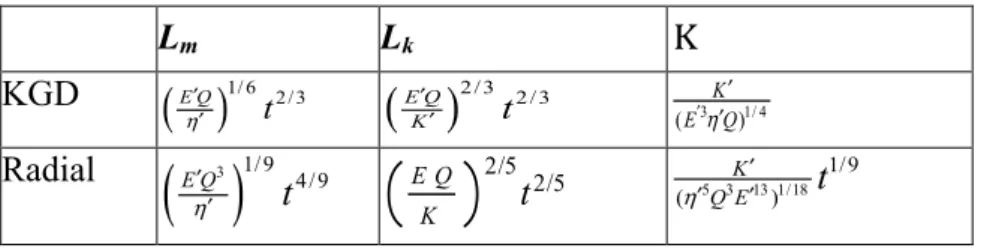
) in the leading order term, with a stress singularity weaker than predicted by linear elastic fracture mechanics. The dominant dissipation mechanism is due to the pumping of viscous liquid into the fracture tip (Poiseuille flow) rather than the fracture process itself. Solutions with non-negligible fracture toughness, then, require a fluid lag between the advancing fracture tip and the driving fluid.The strength of the singularity at the crack tip indicates the dominant physical process (83--86). In 2004, Detournay (84) summarized this work for fracturing in impermeable rock, qL =0, considering both the radial and plane strain KGD
fractures. Absent of leak-off, a dimensionless toughness
( )
m k p L L=
K
identifies if the fracture process is dominated by viscosity (K ≤1) or fracture toughness (4 ≥
K ). The exponent p is 5/2 and 3/2 for the radial and KGD fracture,
respectively. Expressions for Lm and Lk, along with the controlling ratio K are
the same physics for all time, as determined by the temporal invariance of the parameter K . The radial fracture exhibits a
t
19 time dependence, indicating thatthe dominant dissipation mechanism changes from viscous dissipation to fracture toughness dominated at long times.
<COMP: PLEASE INSERT TABLE 3 HERE>
3.3.1. ASYMPTOTICS WITH LEAK-OFF. Inclusion of leak-off for permeable formations adds an additional dissipation mechanism; relaxation of the impermeability condition permits fluid accumulation in the formation, in addition to the fracture. Lenoach (87) considered leak-off with a viscosity-dominated fracture and Bunger et al. (88) consider leak-off in the toughness-dominated case. Subsequently, Garagash et al. (86) has presented a generalized approach where leak-off, storage in the fracture, along with viscous and toughness losses are all active within the fracture and at the tip. This unifying approach verifies that previous analyses (as detailed in (86)) are obtained as limiting cases of the general problem. Tip asymptotics can be used to indicate the dominant mechanisms in planar fracture propagation. A recent review, highlighting the multi-scale and time dependence of the leading phenomena at play during creation of a hydraulic fracture, is provided by Detournay(citation). Verifying the regime in which a hydraulic fracture will be propagating is of crucial importance in the design of laboratory tests and small scale experiments to understand the behavior of a hydraulic fracture. Improper scaling of the dominant physics yields results that are purely of academic interest and cannot be practically exploited.
3.4. Transport of solids in hydraulic fracturing
Solid particles are injected to sustain fractures of the desired geometry against closure stresses imposed by the reservoir. Fractures which close before, or during, hydrocarbon production severely limit the efficacy of the fracturing process. Injected particles are transported by the fracturing fluid to minimize the as designed and final fracture dimensions. A straightforward dimensional analysis provides insight to the transport phenomena at play during creation and
propagation of the hydraulic fracture. The geometry of the fracture (w, h, l), the injection rate (Q , or shear rate γ&), fluid rheology (chiefly: viscosity η, relaxation time λ, fluid density ρf), and proppant properties (solids volume fraction φ,
radius a, density ρs) frame the geometric and dynamic scales, and appropriate
dimensionless parameters in the fracturing process. Application of the
Buckingham Pi theorem to the variables
( , , , , , , , , )
w h a
φ ρ ρ η λ γ
s f&
forms a set of six dimensionless groups, two purely geometric (Π =1 w h/ , Π =2 w a/ ), three dynamic (Re
w=
ρ γ η
fw
2&
/
, Wi= &λγ , Sk= Δρ γ ηaw&/ ), and the volume fraction, φ. Here,Δ = −
ρ ρ ρ
|
s f|
is the density difference. The geometric parameters define the aspect ratio of the fracture (w/h), and the aperture as measured by the particle size (w/a). The relevant dynamic conditions of the flow are indicated by the dominance of viscosity versus inertia through the Reynolds number (Re), the flow timescale versus the fluid relaxation time through the Weissenberg number (Wi), and the importance of particle inertia in unsteady flows via the Stokes number (Sk). The shear rate, γ&, varies throughout thefracture and can be computed from the flowrate and the fracture geometry. Here, we choose the simple relation,
γ
&
=
Qw h
− −2 1, assuming flow in a slit. Note also that a particle-based Reynolds number can also be defined,Re
p= Π
2−1Re
w.Additional physical variables give rise to additional dimensionless groups. These groups will reflect the important physics of the transport process, and the rheology of the complex fluid in the fracture. A Shields parameter, for example, captures the ability of a slickwater treatment to transport proppant particles settled along the bottom of a fracture. Further, we could quite reasonably specify a particle settling velocity to compare against the flow velocity, a wall roughness or channel bend radius to compare against the channel width or particle size (53,
99), a thermodynamic energy scale to compare against viscous dissipation around the particle (100), or additional timescales for the fluid rheology or pumping schedule.
These models highlight expected geometric and dyanmical scalings associated with fluid selection. Parameterizaton of the particle-laden fracturing fluid is often relegated to the magnitude of the viscosity only, occasionally also capturing shear rate dependence (82). The fracture geometry depends weakly on the viscosity: For a PKN fracture geometry, the length scales with the viscosity as
1/ 4
η
−l :
, width asw
:
η
1/5, pressure asΔ :
p
η
1/4. Fluid viscosity must thus be varied by orders of magnitude to significantly alter length and width. However, assuming simple Darcy flow into the formation, 1L
C : η, and Nordgren’s crossover time scales as
t
*:
η
7/3, indicating a strong viscosity dependence for leak-off. Settling also depends strongly on the viscosity; the Stokes settling velocity of a suspension with volume fraction φ scales as 1 5max
(1 )
u: η− −φφ (101).
These scaling considerations highlight contradictory fluid requirements, and the need for complex fluids in hydraulic fracturing. The implications are significant: a fluid designed to create large fracture widths (high viscosity) will also exhibit low leak-off resulting in a long fracture closure time. This long closure time will result in proppant settling to the bottom of the fracture, leaving the top part mostly un-propped and it will re-seal during leak-off reducing the net flow of reservoir fluids. Thus, a large viscosity is required during pumping and a small viscosity is required to aid leak-off before proppant can settle. Further examples include: (1) low pressure drop in the pipe and the simultaneous creation of fracture width, (2) low leak-off during fracture creation but fast fracture closure after pumping has stopped with low damage of the rock permeability (102), and (3) transport of solid particles whilst providing maximum permeability of the placed proppant pack to hydrocarbon fluids.
Three main routes exist to optimize between these conflicting requirements. A ‘train of fluids’ is often used: For example, creation of fracture complexity requires a thin, solids-free fluid. A slurry created by adding solids to the base fluid will not create enough fracture width to admit large concentrations of proppant particles. Therefore, a sequence of at least two different fluids is preferred: a low-viscosity fluid to propagate the leading edge of the fracture, followed by a particle-laden fluid with a larger viscosity. A second route to
address this fluids design challenge is the use of additives to decouple fluid properties: for example, starch particles can be added to control leak-off. A third route is to use fluids whose properties can be altered with time and temperature.
4. FRACTURING FLUIDS
The formulation and properties of hydraulic fracturing fluids vary greatly in response to performance requirements that re set by constraints on the surface and downhole (citation). The choice of fracturing fluid is largely set by reservoir properties, which are strongly variable across different reservoirs (if not within a particular reservoir). Thus, a complex design of the base fluid must be performed for each job. Today, this design is largely empirical and is guided by return on experience.
Fracturing fluid design is constrained. All fluids should: (1) have minimal environmental impact, (2) be easy to mix/hydrate in water with varying ion content, (3) be easy to pump with low pressure drop in the wellbore, (4) be able to travel 1--5 miles through the pipe (typical pipe diameter is 4.5”) and transit the perforation (aperture of about 1” diameter connecting the wellbore to the
formation) without significant pressure loss and material degradation, (5) be compatible with the formation, (6) generate a high pressure drop in the fracture to create fracture width, (7) transport the proppant, (8) minimize leak-off during fracture creation, (9) (but) maximize leak-off after proppant placement to hasten fracture closure, (10) have low residue content to minimally alter
fracture/proppant pack conductivity, and (11) limit proppant flowback during hydrocarbon production. In spite of these (often contradictory) requirements, typical fluids cost less than $1/liter (citation).
Fluids designed to meet these requirements are complex. Additives, both chemical (such as polymers) and physical (e.g. spherical particles and fibers) endow the fluid with a non-Newtonian response in which the stress varies
nonlinearly with the shear rate, and changes also as a function of mechanical (and thermodynamic) variables. Other important non-Newtonian characteristics
include strain-dependent stresses, viscoelasticity, thixotropy, and a finite yield stress during shearing, amongst others (105, 106). Importantly, non-Newtonian
fluids can also exhibit normal stresses which are not observed in Newtonian fluids; normal stresses give rise to several important phenomena, including elastic tension along streamlines (105, 107), particle migration (108, 109), and elastic instabilities (110, 111). The various processes described here, and how they manifest in the fracturing process, are shown schematically in Figure 2.
<COMP: PLEASE INSERT FIGURE 2 HERE>
Figure 2 Schematic diagram of the fracturing process (above), and various transport phenomena involved in hydraulic fracturing.
The majority of fracturing fluids used today are aqueous (9). Diesel, alcohol and other organic-based fluids, while desirable since they tend not to cause formation damage and are easily viscosified, tend not to be used as they are hazardous to pump at high pressures and in large volumes (104). Both aqueous and organic fluids can be foamed (or ‘energized’), and all are eventually filled with proppant. Due to the proprietary nature of fracturing fluids, definitive information on components and concentrations are not generally available. Also, the chemical structure of components can be ambiguous. Reviews by Barati and Liang (197), Montgomery (104, 198), Gulbis and Hodge (192), and Ely (103) describe many chemical and physical properties of commonly used fracturing fluids. We summarize material properties and parameters within the
supplementary material; follow the Supplemental Material link in the online version of this article or at http://www.annualreviews.org/.”
4.1POLYSACCHARIDE-BASED FLUIDS.
Polysaccharide-based fluids are inexpensive and effective viscosifiers, achieving desired fracture widths and reduced proppant settling. Most of these materials are well-studied (200). Guar is the most common polysaccharide used in hydraulic fracturing (198). It is mostly soluble in water (the residue varies depending on the guar), biodegradable, presents low health concern (it is
commonly used as food additive), and can be readily broken. Xanthan gum and cellulosic materials are also used. Xanthan is less-common owing to its higher cost, and materials modified from cellulose (which is itself not soluble in water)
are also used since they have fewer impurities than guar (192) and easily form gels when derivitized (e.g., hydroxyethyl cellulose or HEC) (200). Here, we focus on guar exclusively, as guar-based fluids can answer all of the
requirements enumerated above. Consequently, guar based fluids have been the fracturing fluid of choice for decades.
Uncrosslinked, or linear, guar consists of a mannose backbone substituted galactose with an average ratio 1.8 mannose (201). Uncrosslinked guar behaves as a viscoelastic shear thinning fluid (202). The galactose units are commonly modified (192) to change (i) the solvation properties of the guar, (ii) the
availability of crosslinking sites and chemistries, and (iii) the performance of the material at elevated temperature. Typical guar concentration is 0.5 wt%,
providing viscosity of the order of 0.1 Pa.s at 170s-1 and room temperature (citation).Borate and various metal ions crosslink the linear material to a physical or chemical gel. Crosslinking with borate requires elevated pH (â 7.5) (190, 197), resulting in a dynamic ionic bond in which the borate ion connects
cis-diols on the galactose. The dynamics of these crosslinks have been
extensively studied (191, 203), and they give rise to a classical Maxwell-like linear viscoelastic response of the material (190) and a more viscous solution (as compared to the uncrosslinked case) in steady shear that can also display shear thickening above a critical shear rate (204). Crosslinking with metal ions is performed over a larger range of pH (depending on the ion) (192), and gels crosslinked with zirconate can tolerate a higher downhole temperature than with borate (197). Since the metal crosslinked guar forms a chemical gel, shearing disrupts the bonding network and the gels do not completely reheal (193, 197). Temperature and pH accelerate the crosslink reaction, while the addition of organic molecules (ligands) can delay it. Pressure also affects the rheology: a decrease of 70% was reported in the viscosity of 0.3wt% hydroxypropyl guar crosslinked with diboronic acid when pressure was increased from atmospheric to 10,000psi (citation). Water chemistry (pH and ion content) must also be monitored, as species like bicarbonate, phosphate, magnesium, iron, and silicate can affect the crosslink density and hydration state of the guar (citation).
Guar is often injected with delayed crosslinker and a breaker to modify the fluid rheology away from surface equipment. Ideally, crosslinking would occur
immediately before the fluid transits the perforation to the fracture: (1)
Crosslinking in the wellbore subjects the fluid to high rates of shear (typically 500-1,500 s-1), and may irreversibly damage the crosslinked network. (2) Crosslinked guar is more viscous and more difficult to pump, limiting the pumping rate (citation). (3) Crosslinked guar more effectively carries proppant into the fracture preventing sand from settling to the bottom of the pipe instead of entering the fracture. Even when crosslinking is delayed, the gel is exposed to extremely high shear rates in the jet-like flow through the perforation. Thus, the ability of the gel to heal and recover must be quantified to ensure that the desired rheological properties of the fluid are retained in the fracture. The breaker is added to degrade the guar (crosslinked or uncrosslinked) once the fracture has closed (192). Degradation is necessary to ensure that the ultimate conductivity of the fracture is not hindered by the presence of a viscous fluid, or residual
polymer. Oxidizers and enzymes can be used (such as β-mannanase) to cleave the acetyl linkages connecting mannose--mannose and mannose--galactose groups (citation, 205).
Breaker: Additive to reduce fluid structure and viscosity.
4.2VISCOELASTIC SURFACTANT-BASED FLUIDS.
Micellar surfactants in water constitute the so-called viscoelastic surfactant (VES) class of fluids. Introduced because of simplicity in design, preparation, and breaking requirements, the rheology of VES can be tuned by varying the surfactant concentration and also the amount and type of salt or co-surfactant added to water. Since the surfactant molecules are amiphilic and relatively short-chained (as compared to polysaccharides), these fluids do not require time to hydrate and generally build structure rapidly upon addition to water. Above the critical micelle concentration, the VES forms long worm--like structures that continuously break and reform, endowing the fluid with a Maxwell--like viscoelastic response (206). This microstructure is perturbed and the fluid thins when flowing through the high shear perforation (like guar). Since the proppant-carrying ability depends critically upon the viscosity, the crucial design
parameter is the fluid rehealing time versus the proppant settling time in the near-perforation region. If the fluid does not recover sufficiently fast, the proppant will settle, accumulate, and occlude the perforation resulting in screenout. The micellar fluid rheology is also strongly temperature sensitive; VES are only typically used in formations below 115˚C.
VES has additional benefits: A breaker is not required when the formation contains mobile water. In other cases, VES can be broken by dilution with injected water (citation). Permeability damage is reduced in the formation and proppant pack as the surfactant micelles can dissolve in both aqueous and organic liquids. The strain-hardening extensional viscosity of VES reduces leak-off in formations with small pores. Furthermore, the rheology of such systems can be tuned such that the very high shear rate rheology translates into low frictional pressure losses in the pipe (in turbulent regime), eliminating the need for a cross-linker. The main disadvantage, however, is the low pressure drop they create in the fracture (related to their shear banding). To remediate this issue and ensure enough fracture aperture for proppant placement, VES are generally foamed. While much is known about unladen VES, the current body of knowledge has not enabled a clear link between the structure of the surfactant and the resulting properties of the slurry, limiting the development of this family of fluids.
4.3ENERGIZED FLUIDS, FOAMS, AND EMULSIONS.
All of the fluids described above can be energized (foamed) with nitrogen and/or carbon dioxide, and can also be added as inclusions in an immiscible organic fluid to build an emulsion (197, 198). Energized fluids and foams have the advantage of reduced water usage, while maintaining proppant transport ability. Furthermore, energized fluids require little or no breaker (the foam life can be controlled by surfactant chemistry), and tend not to damage the formation since a majority of the material (by volume) pumped downhole is gas and not water or oil (192). The rheology of foams and emulsions can be tuned through the fraction of the various phases, distribution of the size of the dispersed phase, and the interfacial tensions of the phases (106). Foams can exhibit viscosities far greater than the liquid phase and can exhibit a yield stress (207): they thus