Composition and Correctness
of Heterogeneous Planning Systems
by
Nicholas Pascucci
B.A. Computer Science, Colorado College, 2012
Submitted to the Department of Aeronautics and Astronautics in partial fulfillment of the requirements for the degree of
Master of Science at the
MASSACHUSETTS INSTITUTE OF TECHNOLOGY June 2019
c
Massachusetts Institute of Technology 2019. All rights reserved.
Author . . . . Department of Aeronautics and Astronautics
May 23, 2019
Certified by . . . . Brian C. Williams Professor of Aeronautics and Astronautics Thesis Supervisor
Accepted by . . . . Sertac Karaman Associate Professor of Aeronautics and Astronautics Chair, Graduate Program Committee
Composition and Correctness of Heterogeneous Planning Systems
by
Nicholas Pascucci
Submitted to the Department of Aeronautics and Astronautics on May 23, 2019, in partial fulfillment of the
requirements for the degree of Master of Science
Abstract
Autonomous systems present many new opportunities, especially for exploration in haz-ardous environments. One technique for building increasingly capable planning systems is to compose existing planners to enable specialization and division of subproblems. These systems require new analysis techniques, appropriate for ensembles of planners, if they are to be trusted with safety- and mission-critical roles in the future. Current state-of-the-art techniques address parts of this problem—including analysis of middlewares such as ROS and complex control systems—but have not yet provided analysis methods to ad-dress the particular correctness needs of composite planning systems. Applying formal methods to model the internal communications of planning architectures is a promising way to address this gap.
In this thesis, I develop a formal modeling method which enables proofs of correct-ness for planning system architectures which use a rich common data structure for both their inputs and outputs. The method is demonstrated through a case study of Enterprise, a system of planners developed at the MIT Model-Based Embedded and Robotic Systems (MERS) group which communicate using the Qualitative State Plan (QSP). The verifica-tion requirements of this system inform the development of a formal semantics for first order logic, defined in terms of the common data structure, which is useful for modeling systems of planners. Sentences in this logic can be used to express formal specifications about a planner’s behavior, including correctness properties which are important for au-tonomous operations of critical systems. Using the logic one can also describe systems of planners built around this common data structure. Modeling of the Enterprise architecture and components in the case study demonstrates the usefulness of the technique.
The analysis method allows varying the level of abstraction by permitting the assump-tion of certain component behaviors by the architect. This allows the analysis to treat planners as “black-box” implementations while describing the rest of the system. Systems of planners can be described using specification composition, which enables description of various architectures. The use of intuitionistic mathematics enables mechanization of the logic in a variety of computer proof assistants to enable machine-checked proofs and implementation of planners by refinement from specification. Mechanization and oppor-tunities to extend the method to more expressive logics are discussed as future work. Thesis Supervisor: Brian C. Williams
Acknowledgments
Defining, researching, and writing a thesis is not an easy task in the best of times but it is made more so by the love and support of those around me. I want to thank all of those who helped me get to where I am today, and those who helped me create the work you are about to read.
To my lab-mates at the Model-Based Embedded and Robotic Systems group: thank you for your support, insight, and feedback on a project which did not quite fit the mold, and for putting up with my abstract nonsense. Thanks to the Scouts group for being a great team and bringing me on many adventures.
To my girlfriend, Lauren: thank you for supporting me, understanding me, and al-ways being there; for rubber-ducking and talking to me about abstract nonsense over scotch.
To Ethan: thank you for sparking my interest in category theory and formal methods and for teaching me so much about it, in addition to being a supportive and caring friend.
To all of my friends and family: thank you for helping me grow and become who I am today. Without you I wouldn’t be here.
And finally, to Brian: thank you for giving me the chance to explore an area outside the norm for the group, and for your advice along the way; I hope that this work opens new horizons, as mine have been opened.
This research was funded by a grant from Exxon Mobil Research and Engineering Corporation through the MIT Energy Initiative, Award 023730-00025.
Contents
1 Introduction 15
1.1 Motivation . . . 15
1.2 Approach and Innovations . . . 18
1.3 Structure of the Text . . . 19
2 Related Work 21 2.1 Testing Autonomous Systems . . . 21
2.2 Applications of Formal Methods to Autonomous Systems . . . 23
2.3 Verifying Internal Message Semantics of Autonomy Architectures . . . 26
2.4 Summary . . . 27
3 Architectural Models & Problem Statement 29 3.1 Notational Conventions . . . 29
3.2 Problem Statement . . . 30
3.3 Modeling and Specifying Architectures . . . 30
4 The Enterprise System Architecture 37 4.1 Architectural Principles of Enterprise . . . 37
4.1.1 Common Representations . . . 39
4.1.2 Service Discovery and the Metadata Endpoint . . . 40
4.1.3 State Management . . . 41
4.2 Application: Undersea Exploration as a Space Analog . . . 42
4.2.1 Deployment: Au’Au’ Channel, Hawai’i . . . 43
4.2.2 Deployment: Puntarenas Province, Costa Rica . . . 45
4.3 Correctness, Validation, and Verification in the Modularized Architecture . 47
5 Logical Foundations 49
5.1 Introduction . . . 49
5.1.1 A note on notation . . . 50
5.2 Fundamentals of Intuitionistic First-Order Logic . . . 50
5.2.1 Historical Background . . . 51
5.2.2 Signatures of First Order Logics . . . 53
5.2.3 Heyting Algebras . . . 55
5.3 Case Study: Qualitative State Plans (QSPs) . . . 61
5.3.1 Temporal Constraints . . . 62
5.3.2 State Constraints . . . 64
5.3.3 Definition of the Qualitative State Plan . . . 66
5.3.4 Use of Constraint Systems for Models, Goals, and Solutions . . . 68
5.3.5 The Heyting Algebra of Qualitative State Plans . . . 70
5.3.6 Evaluating FOL Formulae in the Heyting Poset . . . 73
5.4 Extensions: Abstraction and Refinement of Constraint Systems . . . 74
6 Application to Modeling and an Enterprise Case Study 77 6.1 Abstract Architecture of Enterprise . . . 77
6.2 Modeling Activity and Path Planners . . . 78
6.2.1 Common Properties . . . 79
6.2.2 Leaf and coordinator planners . . . 81
6.3 Entailment of Specifications and Internal Models . . . 84
6.4 Example: Describing Sulu . . . 86
6.5 Example: Describing ScottyPath . . . 87
6.6 Example: Specification as a Design Aid . . . 89
6.7 Summary . . . 91
7 Conclusion 93 7.1 Summary of Contributions . . . 93
7.2 Future Work . . . 94
7.2.2 Logical Extensions . . . 94 7.2.3 Flexible Architectural Models . . . 95
List of Figures
3-1 An example system diagram showing the functional tree structure created
by an architecture. . . 32
3-2 Concretization of an architecture using an instantiation table. . . 34
4-1 The original, simplified, Enterprise system architecture. . . 38
4-2 The revised system architecture, as of 2019. . . 38
4-3 A block diagram showing the virtual machine architecture used in the Hawai’i deployment. . . 44
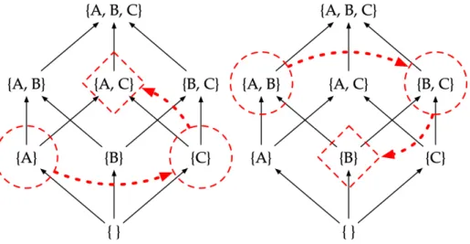
5-1 The join{A} ∨ {C} = {A,C}and the meet{A,B} ∧ {B,C} = {B}. . . 57
5-2 A basic temporal constraint network consisting of two events and one con-straint. . . 62
5-3 A region defined by the intersection of half planes. . . 65
5-4 In this illustration, an agent must remain between walls which move over time. . . 65
5-5 An example QSP describing a high-level plan for a fictitious UAV. . . 67
5-6 The goal model QSP for the firefighting example. . . 69
5-7 The plant and obstacle model QSP for the firefighting example. . . 69
6-1 An example system containing both coordinator (A) and leaf planners (B, C). 81 6-2 A possible problem decomposition for the example architecture. . . 82
6-3 Commutative diagram specification for decompose, refine, and compose. . 83
6-4 Abstract architecture, instantiation table, and concrete architecture for the leaf planner Sulu. . . 86
6-5 Abstract architecture, instantiation table, and concrete architecture for Scotty paired with an “identity” planner. . . 87
List of Tables
5.1 The relative pseudocomplements (x → y) for all pairs of x and y in the {A,B,C}lattice. . . 60
Chapter 1
Introduction
1.1
Motivation
Robotic systems are becoming increasingly capable as technology improves. Advances in miniaturization have provided raw computational horsepower, allowing each new system to incorporate greater levels of artificial intelligence (AI) than its predecessors. In turn, these more capable robots are tasked with more and more difficult missions. Among these diverse applications of AI, space exploration presents both unique opportunities and unique challenges. Robots have cemented their role as the key agents for human space exploration in part due to their robustness, expendability, and low cost relative to living explorers. As our abilities to explore the solar system grow our machines are at the vanguard, venturing into new and more hazardous destinations. To succeed at the challenging missions we have created for them they will need to operate independently and autonomously, and to respond to unforeseen challenges while still achieving their mission objectives.
How best to achieve a high level of autonomy remains an area of active research, with model-based techniques presenting a promising approach. Provided with logical representations of their world, themselves, and their goals, these agents are able to reason using these models to determine the best course of action available to them. Model-based methods formed the basis of the first artificial intelligence system to control a spacecraft independently: the Remote Agent Experiment (RAX), launched aboard the Deep Space 1 spacecraft in 1999 [1]. As part of NASA’s New Millennium Program (NMP),
increase the likelihood of mission success. Although the project achieved its validation objectives [2], the vision of routine, frequent operation of fully autonomous, self-operating
spacecraft espoused by the Remote Agent team [3] has yet to come to fruition.
A handful of successor projects have incorporated advanced autonomy technology into NASA spacecraft since, but none have reached the level of independence that pro-ponents of the New Millennium Program had anticipated. Despite the NMP motto of “faster, better, cheaper,” [4] NASA spacecraft remain costly to develop in both time and
money. The resulting conservatism with regard to new technologies requires that only those deemed either low-risk or absolutely necessary for mission success are flown. New technologies are able to make inroads when the mission parameters dictate their use— see, for example, the limited automatic scheduling capability of the James Webb Space Telescope [5]—but overall the use of onboard autonomous systems remains rare despite
their potential benefits. This is due in part to concerns about how to integrate these tech-nologies into existing operational and technological structures, and in part due to a lack of trust in autonomous systems.
Gaining trust in AI systems is difficult, largely due to the unfortunate truth that in-creased capability generally comes at the cost of inin-creased complexity. We require the systems playing a leading role within complex and expensive spacecraft to meet a high bar of quality and reliability. Standard flight control software deployed in a safety- or mission-critical role must meet certification requirements vouchsafing its suitability for the job. One might expect autonomous systems to be certifiable under these same guide-lines, but due to their adaptability they are even more complex than “standard” software and testing their correct function in more than a trifling portion of the possible states the program may enter is next to impossible [6]. To provide a certification of correct system
function suitable for mission critical software, more powerful techniques must be used. Formal methods provide a possible way forward. By describing systems at a higher level of abstraction, formal analysis techniques are able to cope with the increased com-plexity more gracefully. They also provide stronger guarantees of correct behavior in the form of logical proofs that systems satisfy their specifications. Recent developments in the use of “lightweight formal methods” [7] have shown that the application of rigorous
modeling and analysis techniques during the design stage is a useful tool for identifying conceptual errors at a reduced cost, and identifies bugs that testing does not.
In this thesis I demonstrate a first-order logical language aimed at this conceptual-design niche. The logic is suitable for writing specifications of correct behavior for AI systems built by composing several heterogeneous planners, which I term “composite planning architectures.” This language focuses on semantic-level modeling of the com-munications between planners, as opposed to verification of the internals of the planners themselves or modeling of the communication channel. It is defined using a constructive mathematical basis that makes it suitable for use in computer proof assistants and as the starting point for correct-by-construction implementations using refinement techniques. Combined with an architectural modeling technique that can capture architectures at a variety of abstraction levels, we have the beginnings of a powerful tool set for designing and verifying composite systems.
To help motivate the development of the logical foundations of this language, I will provide examples throughout the thesis grounded in the Enterprise planning architecture developed by the Model-Based Embedded and Robotic Systems Lab (MERS) at MIT.
En-terprise is itself a composite planning architecture, with a number of activity and path
planners communicating to solve planning problems cooperatively. These planners use a common problem format, the Qualitative State Plan (QSP), that is both flexible enough to describe broad classes of planning problems and useful as the basis for planner specifica-tions.
In the following chapters I develop the logical framework needed to provide semantics for first-order logic in terms of any data structure with the correct algebraic properties. I characterize QSPs and the planners operating on them, demonstrate that such a logic exists for QSPs, and how it can be used to perform analyses of the composite planning system at an architectural level.
To set the stage for these developments, we will first need to set a common modeling paradigm and lexicon. The next section provides definitions of the terminology used in the thesis, including architecture, component, and specification; a brief discussion of the modeling approach; and the formal problem statement guiding the research.
1.2
Approach and Innovations
Providing a useful tool for answering the specification problem involves modeling dif-ferent aspects of the system in difdif-ferent ways. From a structural perspective, we require models of system components at a level of detail that enables proofs of their behavior, given the components they depend on, to be constructed. These proofs in turn are used to support specifications of component behavior expressed in terms of the logical prop-erties of the messages exchanged between components, including simple propprop-erties such as termination or correctness with regards to constraints, and complex ones such as a guarantee of least-commitment. Finally, at an architectural level we need to model the concretization process and show that it maintains the invariants established by the previ-ous work.
Scaffolding for this process is provided by the semantics imposed by the structure of the messages exchanged between components. In following chapters I will examine what it means for a message type to have sufficient structure for these semantics to be defined. As an example of this approach we will examine the Qualitative State Plan (QSP) structure deeply, demonstrating that it can support a semantics for intuitionistic first-order logic by showing that the set of QSPs forms a Heyting algebra. I then show how sentences in the specification logic encode specific sets of these objects that are exchanged between planners and satisfy certain properties. These properties in turn are a useful basis for proofs of correctness of the planners themselves as they provide both axioms and goals.
I also provide a number of worked examples demonstrating how to apply the logic to architectural problems, using Enterprise as a case study. Alongside formal descriptions of a common set of desirable properties, I present more detailed specifications of two plan-ners: Sulu [8] and ScottyPath [9]. These planners are arranged into a number of example
architectures whose properties I explore, leading to an example of how to use the logic for specification of novel systems. The logic is used during the design process to either support the safe reuse of existing planners or to create new ones using the specifications as a basis for implementation using correct-by-construction refinement techniques.
1.3
Structure of the Text
The following chapters discuss the background of research against which this work was done, the details of the specification logic, and a case study for the Enterprise compos-ite planning system. Chapter 2 discusses related work with a focus on the analysis of complex spacecraft autonomy systems and existing formal approaches to modeling and verifying them. Chapter 5 describes in detail the mathematical foundations of the veri-fication logic, with a case study examining the Qualitative State Plan structure used by
Enterprise. Chapter 4 describes Enterprise in greater depth, motivating its design through
real-world research deployments in oceanography. Chapter 6 then discusses the intrica-cies of modeling and a case study using Enterprise. Finally, Chapter 7 concludes the thesis with final thoughts and possible areas for future research.
Chapter 2
Related Work
The body of knowledge regarding analysis of autonomous systems is growing rapidly, as intelligent systems penetrate daily life and more attention is paid to certifying that these systems behave appropriately. A variety of approaches have been taken, including model-based and formal methods; however, the literature to date has focused primarily on either component-level analyses or concurrency problems and not sufficiently addressed the semantics of the internal communications of autonomy architectures in a formal way. The limitations of previous approaches to analysis and testing of autonomous systems, primarily the complexity of these systems and limited abstraction, are being eroded by recent developments in lightweight formal methods. In this chapter I describe the state of the research as of this writing, and point to gaps in the field that this thesis begins to fill.
2.1
Testing Autonomous Systems
Artificial Intelligence systems are beginning to permeate safety-critical systems across a number of terrestrial industries. Computer-controlled cars, planes, and factories are on the forefront of autonomy adoption and valuable lessons have been learned from their efforts—both successful and not. A key challenge encountered by all of these systems is that formulating good acceptance criteria for autonomous systems is quite difficult, due in part to the inherent complexity of software systems and in part to the necessity of modeling the operational context in determining the behavior of an adaptive system.
software is able to take on a practically limitless number of possible states. Exhaustive testing of the state space is impossible for most software systems due to time and space constraints [10] [11]. Additionally, the behavior of the system in each of these states can be
quite difficult to analyze as, due to the discrete mathematical nature of software systems, many traditional (i.e. continuous) engineering analysis tools do not apply [12]. For
model-based AI agents, this difficulty is compounded because these systems operate at two levels: they contain models of the agent and its environment, along with a reasoning engine operating on those models. Models require different validation approaches from engines and have different lifecycles [13], with the engine being reusable across multiple
models and models being tied closely to the system under control [14]. Because of this,
investments of time and resources into validation and verification of the engines have larger payoffs over multiple missions if the engine can be reused [2].
In aerospace, these verification and validation (V&V) tasks would generally fall under the purview of a project’s systems engineering team. To cope with the explosion in sys-tem complexity brought on by increased hardware and software capabilities, the syssys-tems engineering community has recently turned its attention towards their own model-based techniques known as Model-Based Systems Engineering (MBSE) [15]. MBSE refers to
a broad set of approaches that emphasize capturing system designs and behaviors as a set of computer models, enabling systems engineers to simulate the system and identify problems early in the design cycle. Building the process around computable models, pro-ponents claim, helps to expose assumptions and prevent divergence of understanding between the different parties involved in designing a complex system [11].
One of the existing MBSE approaches for designing spacecraft control systems is the State Analysis/Mission Data System (MDS) framework designed by researchers at the Jet Propulsion Laboratory [16]. The framework combines a modeling and analysis method
(State Analysis) with a set of off-the-shelf software components. These pieces work syn-ergistically to enable engineers to design sophisticated control systems by composing well-understood parts. At its core, State Analysis/MDS is a mechanism for identifying the possible states a system under control can be in and the possible control interfaces that can affect that state, so that the system designer can create a control system. The uniform approach allows techniques like MDS to provide stronger analysis results than previously have been achievable, while operating within finite resource constraints. However, MDS
does not provide guarantees on the system behavior. Making models explicit within a system architecture is a necessary step towards full verification, but it is not sufficient; in the next section, I discuss formal approaches to verification that can provide true “for-all” guarantees.
2.2
Applications of Formal Methods to Autonomous Systems
Taking these techniques a step further, one might consider other types of analyses that can be performed on a system model. As I have already discussed, simulation and testing of a software system is not sufficient to determine correctness due to the large number of states it can be in. To get more leverage in analyzing large systems it is necessary to abstract the system and consider many possible states at once. This is the domain of formal methods.
At a high level, there are two major approaches to the formal analysis of software systems: model checking and theorem proving. Model checking is a fully automatic process that enumerates the possible state trajectories of a system model and attempts to discover paths leading to violations of a user-provided constraint on the system behavior. Current hybrid model checkers such as Alloy [7] are able to examine extremely large state
spaces quickly, but a fundamental limitation of the technique is that it is restricted to a finite set of states. In many cases this may be “good enough”, and a growing body of work in lightweight formal methods encourages the use of model checking systems as a way to discover design errors earlier in the development process [17]. For safety-critical
applications, however, the additional guarantees provided by theorem proving may be necessary.
Theorem proving relies on traditional mathematical techniques to produce proofs of correct behavior for a software system within a sound logical framework. Modern developments are generally supported by computer proof assistants such as Isabelle, PVS, Spark, or Coq, that implement consistency checking routines and programming languages for expressing proofs. Some systems, such as Coq and SpecWare, are designed to support the extraction of verified routines from the proof system itself (c.f. [18], [19]).
By exploiting more powerful mathematical abstractions, proof-based techniques are able to tackle larger state spaces than model checkers. However, they require a deeper
knowl-edge of both the system to be analyzed and the mathematics used to model it than model checking, leading to a higher barrier to entry for these systems and lower adoption among engineering teams [20].
Both techniques have been applied, with mixed results, to the verification of space-craft software. During the course of the Remote Agent Experiment a concurrent effort was made to develop formal models of the system and analyze them for errors. This analysis was performed twice: once during the system development, and once following the identification of a concurrency error during the flight. In both instances the use of model-checking tools (in the first instance SPIN [21], in the second Java Pathfinder [22])
identified concurrency errors, including the flight error. However, these efforts were ex-perimental and required the team to dedicate a large amount of time to modeling the system, with a particular emphasis on reducing the program state space to make model checking tractable. Most of the validation of Remote Agent was performed using scenario based testing instead of formal methods, though in the final Remote Agent DS1 Technology
Validation Report the team stated:
The primary lesson is that the basic system must be thoroughly validated with a comprehensive test plan as well as formal methods, where appropriate, prior to model development and flight insertion. . . .
The RAX experience confirms that testing FSW is hard. The bug that was found during flight shows that more attention and effort needs to be spent validating the basic engines. The validation cost is well worth the effort be-cause the engines are components that can be re-used over many missions. [2]
The view that formal methods are useful but should be focused on slow-changing areas of the system, is a valid one. It indicates that to get the most benefit from formal modeling, the areas of the design that combine highest technical risk and a slow pace of evolution should be prioritized. Towards that end, the recent pushes in formal modeling have focused on the early design phases where mental models are not yet well developed, and where decisions affect large parts of the system and generally remain in place for the system’s lifetime. This is the premise behind Alloy [17] and TLA+ [23], which both
to directly verify a program’s implementation.
An alternative approach is to push the verification further back in the development cycle and embed a runtime monitoring system that can check the execution of the pro-gram against a specification. Because the system only needs to examine a single run of the program, the specifications are generally easier to write, and when combined with a provably-correct recovery system gives more confidence that the system will not enter erroneous states in an unrecoverable manner. These techniques can also be combined with testing to perform verification in the design loop [24], though they do not provide
the same design guidance as the other techniques mentioned previously because they are performed a posteriori.
Ultimately the difficulty in using formal methods lies in how best to use abstractions to reduce the scope of the analysis. Design-time approaches deal with larger blocks of the system where implementation details are ignored. Runtime monitoring focuses on a single execution, rather than all possible executions. Both of these approaches are helpful, because they exploit modularity properties of the system to reduce complexity.
To be useful for analysis of large, complex systems, formal modeling techniques need to be made modular. Mixed-and-matched modeling techniques, applied where appropri-ate at various levels of abstraction, likely present the best balance between automation and confidence that the system contains no errors [20]. Within the robotics community
both model checking and theorem proving have been applied to a number of verification domains ranging from probabilistic validation of system models [13] to analysis of
middle-ware channels in ROS-based architectures [25]. Whether the problem can be formulated
in such a way that a given technique can be applied is a major factor in determining the tools to use.
In the following section, I describe a particular domain that has been under-examined and will be the focus of the analyses in this thesis: semantic-level modeling of com-munications between planners, as opposed to verification of the planners themselves or modeling of the communication channel properties. This approach enables the use of ei-ther theorem proving tools or model checkers for verification, and addresses the question of correctness from a new perspective that is synergistic with other analysis methods.
2.3
Verifying Internal Message Semantics of Autonomy
Architec-tures
Given the finite resources available for V&V, it is important to consider carefully where to apply them in order to get the greatest benefit. The current trend in robotics software design is towards component-based architectures where systems are built by connecting a set of reasoning components together using a middleware system such as the Robot Operating System (ROS). The majority of the verification done on this type of system focuses either on the components or on the middleware. Component verification involves showing that a given piece of software is compliant with a specification—for example, that a planner will not violate a risk bound by design [26] or that a planning system is free of
runtime errors [14]. Analysis of the middleware linking these components tends to focus
on the concurrency properties of the communications channel itself such as messaging latency, queue behaviors, and timeouts [25].
These approaches, either alone or combined, are not sufficient to fully characterize the behavior of the system. This is due in part because they are performed at a level of abstraction similar to that of the system itself. As Leveson argues in [10], to understand
a system holistically one must take a higher-level perspective of it—one that both encom-passes the system and enables reasoning about it using tools not present in the system itself. This is primarily because interactions between components are the driving factor of system-level behavior, and reasoning about these interactions holistically requires looking at the system from the outside. Emergent behaviors, those which arise from the interac-tions between components in a given system rather than from the individual components in isolation, are invisible unless the system is examined in this way [10].
One implication of this line of reasoning is that there is no singular approach to for-malize this type of meta-analysis that applies in all situations. The existing analysis methods are incomplete; among the missing pieces, the robotics community lacks a sys-tematic method for analyzing the communications that occur between components at a semantic level—i.e. what do the messages mean, within the problem domain—as a distinct perspective from looking at the properties of the communications channels car-rying those messages. This perspective is desirable because while failures in the com-munications channel may ripple out through the architecture, semantic mismatches in
the inter-component communications can have direct effects on system behavior even in the absence of component failure [10]: consider the scenario where a high-level
plan-ner dispatches sub-problems to child planplan-ners in a way that does not respect constraints between the sub-problems. Describing the communications flows at this level gives us another powerful viewpoint on systems of reasoning components that we did not have before.
This thesis describes an approach to connect the logical semantics of these messages to a symbolic language, enabling the system designer to write high-level specifications of planner behavior in terms of the messages exchanged with other planners. As a construc-tive mathematical approach, it is suitable for use in model checkers and theorem provers; and, with the help of a suitable tool set such as SpecWare, can enable the refinement and extraction of planner implementations from specifications [19]. Focusing on the logical
properties of the messages is a novel approach to formal specification that has not yet taken hold in the planning community, and that can augment existing approaches to give a holistic view of the system under analysis.
2.4
Summary
Showing that a given software system is free of errors and satisfies its specification is a very challenging problem. AI systems make it even more difficult due to the very proper-ties that make them useful, such as their adaptability and context-sensitivity. Model-based approaches are gaining adoption for the decomposition and analysis of complex systems, and for the task of verifying software the most appropriate models give formal properties that can be verified automatically. The current trend in the application of formal methods is towards earlier, design-time checking of high level system models and specifications.
Theorem proving and model checking are the two major approaches to this verifi-cation, each having different trade-offs; while model checking is easier to use for the non-specialist, theorem proving offers greater expressive power and abstraction enabling analysis of larger systems. Both of these techniques have been applied to robotics prob-lems, largely in either demonstrating that components meet their specifications individ-ually or that communications channels do not introduce system errors. Within the plan-ning community, there does not yet exist an approach to modeling the communications
between reasoning components that can describe the planning problems and solutions exchanged. The approach outlined in this thesis leverages the mathematical semantics of the data structures used to communicate this information between planners to enable architectures to be modeled precisely enough for model checking or theorem proving to be applied.
Chapter 3
Architectural Models & Problem
Statement
In order to address the modeling problem formally, we will require a method for repre-senting architectures in a way that makes them easy to analyze. This chapter outlines the modeling technique used throughout the thesis, and uses it to articulate the formal problem statement.
3.1
Notational Conventions
Throughout the text, I will refer to the following constructs using a common set of iden-tifiers reflecting those used in this chapter.
• T is the generic type of the data structure used to express system models, mission goals, and planning solutions. When the type of an object may be ambiguous I will annotate types using the convention x : U, wherexis the name of an object or variable and Uis its type. The typeT× T should be read as a pair ofT’s.
• A “fat” arrow, =⇒, represents implication within the “meta-logic” used to define specification logic terms.
• A “skinny” arrow, →, has different interpretations depending on the context in which it used. In a type definition, such as for f : X→ Y, it represents the type of a function from type X to type Y. Otherwise, it represents implication within the
specification logic.
• The objectm : T is a model of the system under control.
• The objectg : T is a specification of the goal state that the system must achieve.
• The objectp : T is the output of a planner.
• Planners are represented as functions of the typeT× T → T, where the arguments are the model and goal specifications. In general I will use the symbolsto represent these functions. Function application is written ass(m,g).
• The names of functions within equations and concrete implementations of T are typeset in Roman type (for example, calls(x,y) or x :QSP). In text they are set in a monospaced font, such as calls(x, y).
3.2
Problem Statement
The goal of this thesis is to show how to model software architectures so that they can be analyzed. The following section describes how these models are constructed and imbued with logical specifications in order to allow the designer to reason about their system at all stages of the design process from initial concept to final implementation.
Stated formally, the problem statement is as follows:
Definition 1 (Architectural Correctness Problem). Given a model of a software system
com-prised of an initial architecture A, a set of concrete components C, an instantiation tableI, a set of component specifications Sc, and a system specification Ss, determine if the most
concrete child architecture ofAunderIsatisfiesSs.
3.3
Modeling and Specifying Architectures
To describe a system’s architecture formally, and to write specifications about it, we need a way to make a model of it. This model must capture the salient aspects of the architecture—namely, the components involved in the design and their relationships with each other—while retaining an appropriate level of abstraction. It should make analysis tractable and not unnecessarily restrict the possible implementations of the system.
All of the components for the architectures in this thesis will be planning systems. They interact by passing planning problems to each other in a synchronous, hierarchi-cal hierarchi-calling style. There are several possible implementations of this architectural style, ranging from a single process that only uses its language’s built-in procedure calling mechanisms, to a fully distributed planning architecture that uses network protocols to connect clusters of planning systems together. This modeling approach can be applied whenever the details of how the planners are connected can be safely ignored and only the semantics of the messages passed between planners are considered.
Once we have a model of the architecture, we can write specifications for how the pieces of the model must behave which are encoded in a suitable logic. In this section I explain how models are built, and how specifications are assigned to components in the model. Chapter 5 will provide a deeper treatment of the logic used to write these specifications.
Let us begin from the top, with an architecture.
Models of System Architectures and Components
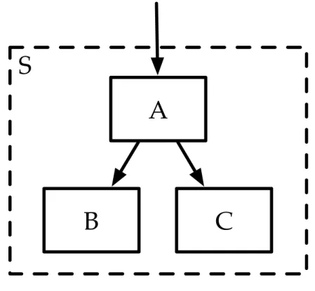
Definition 2(Architecture Model). An architecture model is a connected tree structure with
directed edges, whose nodes are contained in a set of abstract componentsAand a set of concrete componentsC. The edges are defined by a binary relation calls(a,b). When calls(a,b)is true, the componentais able to call on the componentbto solve planning problems; diagrammatically this is represented with an arrow fromatob.
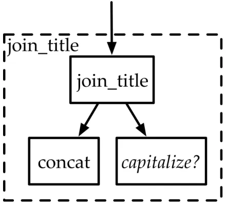
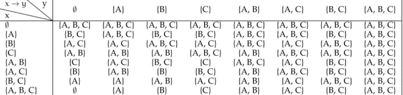
The component models represent both planners and systems of planners as mathe-matical functions. These functions are arranged by their calling relationships into a tree structure, as shown in figure 3-1. In this figure, we see a function join_title which calls two other functions: concat and capitalize?. In this example, we have a function for joining two strings together, and we know that we need a way to capitalize strings but we don’t know how to do so yet. Sometimes we won’t know which specific implemen-tation of a component to use in a given part of the architecture and will need to defer the decision until later. A typical programming approach to this problem is to create a higher order function which can accept another function as an argument, but because the specification logic used in this thesis is first order, we will need another solution.
join_title
concat
join_title
capitalize?
Figure 3-1: An example system diagram showing the functional tree structure created by an architecture.
Instead of allowing higher order functions which would make the logic more com-plex and difficult to analyze, the modeling framework allows parameterization of compo-nents through the use of an “abstract” component. These are named placeholders, like capitalize?, within the functional model of a component that can be bound to different “concrete” component. Binding a concrete component to an abstract component can be thought of in a similar way to the linking stage of compilation. This abstraction allows the structure of the system to be described independently of the components chosen to fill each role.
Definition 3(Abstract Component). An abstract component is an atomic identifier, unique
within the architecture, that represents the use of another component whose implementation is not yet known. A given abstract componentca may be used within the function definition of a
component modelcbonly when the relationcalls(cb,ca)is true.
Definition 4(Concrete Component). A concrete component is a model of a distinct software
component. In this thesis these models represent planning systems and are expressed as functions of two arguments, having typeT× T → T, whereT is the type of the planning problem representation.
Concrete components have a body which defines the details of how its operational behavior is implemented.
Component bodies are not explicitly represented in the architectural model, but in-stead are given in a separate model (c.f. Section 6.3). The component’s body may refer to abstract components, but may not quantify over them or accept them as parameters in order to keep the specification logic first-order.
Note that the type given here for a concrete component differs from the typical one for a planner. A more common representation allows separate types for the initial state, plant model, environment model, and goal model. The approach used here unifies the initial state and goal state into a single state evolution objective, combines the plant model and environment model into a single object representing the invariant constraints of the sys-tem, and represents all of these pieces using the same type. This simplifies the mathemat-ics considerably without sacrificing expressivity in the input representations. Subsection 5.3.4 justifies this choice in more detail; for now, we will defer this discussion and return our attention to the architectural modeling framework.
Making Abstract Architectures Concrete
We now have a mechanism for arranging concrete components, i.e. those we know how to implement, and abstract components, which we have not yet chosen an implementation for, into a hierarchical calling structure. Naturally we may find ourselves with architec-tures that have varying mixes of these two component models, ranging from entirely concrete models to entirely abstract ones. Usually a design will start with a very abstract model. As we discover more information during the design process we will want to be able to make abstract designs more concrete by binding the abstract components to con-crete implementations. This process is called concretization, and uses an instantiation table to tell us which abstract components are bound to which concrete ones.
Definition 5 (Abstract and Concrete Architecture). When an architecture’s set of abstract
components A is non-empty the structure is called an abstract architecture; when A is empty, the architecture is a concrete architecture.
Definition 6(Instantiation Table). The instantiation table is a mapping from abstract
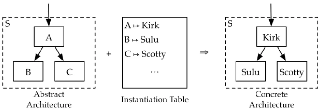
Abstract Architecture S B A C A ↦ Kirk B ↦ Sulu C ↦ Scotty … Instantiation Table + ⇒ Concrete Architecture S Sulu Kirk Scotty
Figure 3-2: Concretization of an architecture using an instantiation table.
table must map every abstract component to at most one concrete component.
The process of converting abstract architectures to concrete ones with an instantiation table is illustrated in figure 3-2. Each abstract component is replaced with a concrete component in an iterative process, each step of which yields a child architecture under the
instantiation table. When there are no remaining abstract components to replace, the child
architecture is fully concrete.
If an abstract component does not have a matching concrete component in the in-stantiation table, the configuration cannot be fully concretized by that table; the result-ing architecture is another abstract architecture that has been partially concretized. This might happen if an architect can’t commit to a particular implementation of an abstract component—for example, it may not exist—but can make decisions about others. This flexibility is an important feature of the modeling technique, because it enables modeling to occur at all stages of the architecture’s implementation, from conceptual design to final implementation.
Because the instantiation table maps each abstract component to at most one concrete component, we can see that the “most concrete” child architecture is the (unique) fixed point of the concretization operation under a given instantiation table, if it exists. When it does not exist the architecture cannot be instantiated; this may occur if there exist cycles within the dependency graph encoded by the instantiation table. This places a restriction on the types of architectures that can be modeled in this formulation.
Our definition of a model, and of the process of concretizing it, is restrictive in the sense that it does not permit circular calling patterns or heterogeneous subtrees that require binding the same symbol to different components. This is primarily a pragmatic consideration for the purposes of the thesis; more expressive formalisms are possible but
require more structure from the specification logic.
Adding Specifications to Architectural Models
Our ultimate goal is to be able to construct a formal proof of correctness for the systems we are modeling. Beyond modeling the structure of an architecture and the components in it, we will also need to be able to attach logical specifications that restrict the behaviors of the components and of the overall system. These specifications will be written in a first order logic, and capture the properties of the components by describing the planning problems that they send to each other.
Definition 7(Specification). A component specification is a first-order logical formula of the
form ∀(m g :T), f(m,g) = x → □, wherefis the name of a component (planning over type T) that may be either abstract or concrete,mandgare the system model and goal specification to be planned for, and□is a placeholder for a sentence in first-order logic defining the properties of the planner solution.
Definition 8(Specification Set). Several specifications can be combined into a specification set.
Each specification may name a different component (fin the definition above), and restricts that components behavior.
Generally an architecture will have a specification set which provides the desired behaviors of its components, and a concrete component will have a specification set that describes the actual properties imposed by its particular implementation.
The core of this thesis is dedicated to showing how the semantics of these specifica-tions is defined. The particulars of the logic are discussed in greater detail in the following chapters. For the purposes of this section, it is sufficient to describe when a component “satisfies its specification under a given specification set”.
Satisfaction of a specification set in this context means that we can demonstrate that when the component is used in a certain architecture it behaves correctly, assuming that the components it depends on also behave correctly. To do this we need to build a proof demonstrating that the truth of the sentence forming the specification of our component is a logical consequence of the component’s implementation. The behaviors of the other components (as given by the specification set) are taken as assumptions or axioms for this proof. Reasoning from these axioms using a model of the component, we are able to
decide whether or not the component will behave correctly in all situations. This process is described in more detail in Chapter 6.
Even if each component meets its own specification in isolation, it may not be the case that the system as a whole does. We must also demonstrate that the top-level com-ponent, the root of the call tree, satisfies its specification given a set of conforming child components.
We can say that an architecture satisfies a specification set if, for any choice of instanti-ation table whose concrete components individually satisfy their respective specificinstanti-ations in the set, the root component satisfies its specification. Because an architecture may be totally abstract or totally concrete, this definition gives us flexibility in modeling differ-ent structures and assessing the impact on the system’s correctness when using differdiffer-ent components.
Chapter 4
The Enterprise System Architecture
Before discussing a case study in applying the logic to a real system, it will be helpful to understand the origins and design of our exemplar. MIT’s Model-based Embedded and Robotic Systems (MERS) group has iteratively improved on a common system for a num-ber of years. This system, known as Enterprise, integrates multiple reasoning components within a unified framework to address planning and execution problems, with an eye towards spacecraft applications. In this chapter I will describe the principles guiding
En-terprise’s development and discuss undersea exploration as an application of the system,
setting the stage for the case study in Chapter 6.
4.1
Architectural Principles of Enterprise
In its original conceptual form Enterprise was described as a layered architecture as shown (figure 4-1), with human-facing components handling plan relaxation and negotiation at the top, a layer of executives and high-level planners in the middle, and a set of lower-level planners and diagnostics systems at the base [27]. This approach was
straightfor-ward conceptually, but in 2017 the implementation of the system had expanded to the point that it needed a renewed focus on the interfaces between planners. The existing ap-proaches to integration tended toward tight coupling between components and difficulty incorporating new components as they became mature.
To give the system more flexibility, enable faster integration of new reasoning com-ponents, and simplify field deployments in 2018 the MERS group redesigned the system around a small number of well-defined application programming interfaces (APIs), as
Spock Adaptive Science Uhura User Interaction Kirk Activity Planning ScottyPath Path Planning
Figure 4-1: The original, simplified, Enterprise system architecture.
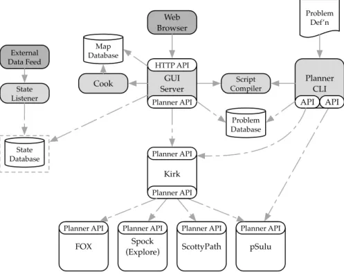
Planner CLI API API Problem Def’n Web Browser Map Database Problem Database GUI Server Planner API HTTP API Cook External Data Feed State Listener State Database Script Compiler Spock (Explore) Planner API pSulu Planner API ScottyPath Planner API Kirk Planner API Planner API FOX Planner API
Figure 4-2: The revised system architecture, as of 2019.
shown in figure 4-2. Reasoning components meeting these specifications would be mod-ular and able to serve a variety of roles both inside and outside a deployed Enterprise instance. Components could be easily substituted for each other, leading to faster testing and validation cycles and enabling researchers to take advantage of common infrastruc-ture. User interfaces and other auxiliary systems would consume the same APIs as the rest of the system, giving them greater utility and a better return on the time and effort invested in building them.
Achieving this level of modularity required that we adopt a common representation for environment, action, and state models; that we provide a way to signal important properties of planning systems (e.g. risk awareness) in a composable way; and that we manage state within the system explicitly.
4.1.1 Common Representations
A common representation for planning problems, system models, and environments forms the communications fabric connecting all of the planners within Enterprise. Prior to the redesign effort various planners would consume and produce related structures in different encodings, making it difficult to integrate systems pairwise1
. For example, the pSulu risk-aware path planner [26] used an in-memory problem representation
imple-mented as a set of Lisp objects, while the ScottyPath continuous-time planner [9] read a
Qualitative State Plan (QSP) represented in the YAML text format from disk. Our main activity planner, Kirk [28], acted as the architectural glue holding together the various
reasoning components and performing impedance matching between their interfaces. An expected consequence of this approach is that Kirk quickly grew in complexity and be-came tightly coupled to the other planners.
To alleviate this problem we required a common representation to be used for planing problems, and for their solutions. For this purpose we adopted the Chance Constrained Qualitative State Plan (CC-QSP) that adds chance constraints2
to the QSP structure dis-cussed in Chapter 5. The CC-QSP was a good fit as it has several desirable properties: it is a superset of the most common plan representations in use among the Enterprise components; it allows expressing constraints on time, location, and risk; and it is easy to represent in a language-independent format. In addition, as I show in Chapter 5, it is possible to give precise semantics to the deterministic (i.e., non-chance constraint) portion of the CC-QSP, which aids in analyzing the system for correctness.
Models of the system under control and of the environment can, in principle, also be encoded as constraints within a Qualitative State Plan. In practice this is encoding is too
1
Various standard problem formats have been used in Enterprise over time, including the Temporal Plan Network (TPN) and Reactive Model Based Programming Language (RMPL). As various planners advanced they implemented their own extensions and diverged from a common representation.
2
Chance constraints are limits on the probability of constraint violation, given a stochastic model of the system under control. A good example of their use is to limit the chance that an underwater vehicle collides with terrain, given unknown currents and model errors.
“final” to provide the flexibility desired; instead, we use a more “initial” representation that encodes vehicle dynamics as Linear Time-Invariant systems within a matrix format and obstacles as GeoJSON geometry. These formats are also well defined, and the ability to model them as QSPs again simplifies analysis of the system.
While the CC-QSP is the current de facto plan representation, the system is able to support multiple formats in a standard way. This is enabled by the metadata system de-scribed in the next section, which gives each Enterprise component the ability to broadcast its own input and output formats and adapt to those of its peers.
4.1.2 Service Discovery and the Metadata Endpoint
To protect the modularity of the system it is necessary to provide a way for components to discover important run-time properties of their peers without having to encode specific knowledge about those peers ahead of time. For example, a component invoking a sub-planner may need to know if it can use the sub-sub-planner to solve multi-agent problems. If it is able to discover the identity of its sub-planner it can gain this information, but this approach can quickly become brittle and prone to failure when another, previously unknown component is used instead. Our solution to this problem was to add a specific API call providing a metadata message that enables planners to inspect their peers.
The metadata message contained, among other data, the following fields:
• The planner’s name;
• its capabilities, as a set of atomic, pre-determined symbols; • supported file formats;
• a version identifier;
• and a recursive listing of the metadata of its own sub-planners.
This is a general-purpose method for planners to discover capabilities provided by their peers, and for other systems such as user interfaces to examine the system structure. Architectural flexibility is maintained by abstracting the planner capabilities into a set of common tag-like declarations. For example, pSulu is risk-aware while ScottyPath is a multi-vehicle planner; other planners can advertise these same abilities when they are
installed in the system and be used in a similar fashion with no changes to the upstream components.
An important consequence of this method is that because each planner is in com-plete control of the capabilities it broadcasts at run-time, it may make decisions about what guarantees it can provide based on the currently-deployed system architecture. As a hypothetical example, a planner that can provide risk-aware planning when given a risk-aware sub-planner but not when given a naïve one may change the capability set it broadcasts based on what it is able to determine from its children’s metadata. This en-ables flexible architectures, and incremental enhancements can be made locally without impacting the global structure.
4.1.3 State Management
When designing a composable system it is natural to imagine each component as a pure, stateless function, transforming inputs into outputs directly and with no side effects. While this model is conceptually quite simple and valuable for analysis purposes, it does not reflect the fact that real systems maintain state and use it for a variety of purposes, not the least of which is to improve their own performance. To preserve the major benefits of the functional approach while enabling components to use state effectively requires taking a principled path towards managing state.
As a motivating example of why state management matters, consider that several of the planners in Enterprise retain the state of their solvers after completing a plan in order to be able to reduce the time required for subsequent planning problems. This “warm start” capability is extremely useful in improving planner performance as it reuses knowl-edge of the problem domain captured in the solver state. At its most beneficial, this type of strategy can act as a memoizing cache and return pre-made solutions to prob-lems that have already been solved. Unfortunately, the naïve approach to implementing this capability—namely, to keep the solver state in memory—carries a number of issues. When planners encounter unrecoverable errors or must be restarted for another reason (such as for a system upgrade) they lose their state. Caching systems are ineffective or potentially incorrect when they do not have access to the entire problem context, includ-ing the solver state. Performance benefits of reusinclud-ing previous solutions are not realized when there are multiple replicas of a planner, and synchronizing their states is difficult.
To address these issues we introduce the concept of a state token. State tokens are an opaque, unique identifier that the planner provides to clients along with the results of a planning session in order to recreate the saved state of the solver3
. They may be implemented in any number of ways, including as a direct encoding of the solver state in the token or as an obfuscated database key pointing to persisted state stored elsewhere. On subsequent requests the client may provide the token to the solver as a “hint” about how to best approach the problem, potentially realizing large performance gains with no compromises in correctness. In addition, because the state is now explicitly encoded in the request context, a number of new architectures are possible that enable the use of caching systems between planners, horizontally scaling planners through replication and load balancing, automatic failure and restart tolerance, and more.
One additional benefit of this approach is that it makes the full system quite easy to model by extending the naïve functional model mentioned at the beginning of this section to include the solver state as an input. By doing so, analysis of the correctness properties of the system is dramatically simplified, and reasoning about state becomes less burdensome. For the purposes of this thesis, we will make the additional assumption (justified by the properties of the planners in practice) that the final result of a planning session is invariant with respect to the state of the planner, and that the only property changing when state is changed is the speed with which that solution is produced.
4.2
Application: Undersea Exploration as a Space Analog
As described in earlier chapters, it is quite difficult to find opportunities to deploy state-of-the-art AI systems aboard spacecraft due to the high cost of such missions and the risk posed by novel software systems. To gain experience with real-world AI assisted missions, the MERS team has partnered with the Woods Hole Oceanographic Institution (WHOI) to deploy Enterprise on oceanographic research expeditions.
These expeditions are a particularly valuable space analog because they provide a challenging and often dangerous environment for robotic explorers, where loss of commu-nication is commonplace. Changing tides and currents along with bathymetric obstacles introduce a number of risks for the vehicles including loss of power, collision with terrain,
3
and inability to complete planned trajectories within timing constraints. These challenges are a good match for Enterprise, which can apply multiple planning techniques to address them.
Space analogies extend to the concept of operations (CONOPS) as well. As part of the proposal for a series of joint MIT-WHOI missions under the auspices of the NASA Planetary Science and Technology from Analog Research (PSTAR) program, the CONOPS for a generic exploration mission was described as involving three primary system roles working in concert: an orbiter, a probe, and a lander. Upon reaching the research site, which may be an exoplanet in the space context or an area of the ocean in the Earth-bound context, the orbiter collects high-resolution mapping data for use in future mission planning and identifies areas of scientific interest. It then dispatches a probe to perform additional reconnaissance to determine if these sites are worth detailed study and to update predictive models used for identifying further visitation goals. Finally, a lander is dispatched to perform more extensive investigation of the highest-value areas. Each of these stages provides more information at a correspondingly higher cost. It makes sense, therefore, to try to quickly identify the best possible use of the most expensive asset (the lander) by targeted deployment of the remote sensor platforms (orbiters and probes).
In the oceanographic context we can draw analogs to these roles: the research vessel with its array of sonars, water column sensors, and surface-based instrumentation is the “orbiter.” A team of low-cost, low-capability autonomous underwater vehicles (AUVs) are the “probes,” and a high-cost but highly capable remotely operated vehicle (ROV) is the “lander.” Maximizing the strengths of this joint system while minimizing the costs of operations benefits from powerful planning capabilities.
We have deployed Enterprise on a number of these expeditions, but I will focus pri-marily on the January 2018 mission to Hawaii and the December 2018 deployment to Costa Rica. It was in the time between these cruises that the MERS team converged on the modular architecture described above and began to reap the benefits.
4.2.1 Deployment: Au’Au’ Channel, Hawai’i
In January of 2018 the MERS team was part of a multinational group of researchers aboard the research vessel Falkor, operated by the Schmidt Ocean Institute, whose objective was to explore the coordination challenges implicit in operating large numbers of heterogeneous
AUVs concurrently. Additionally, our scientific objectives also included identifying and capturing imagery of sea bottom coral formations within the Au’Au’ channel between the islands of Maui and Lna’i. Operations during the cruise included the coordination of vehicles from the Woods Hole Oceanographic Institution (WHOI), the Australian Center for Field Robotics (ACFR), the University of Rhode Island (URI), and the University of Michigan (UM).
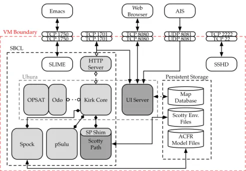
A typical day during the cruise would involve committing to a high-level mission plan developed during the previous evening, which outlined particular deployment zones and asset allocations (e.g. the availability of small boats and Falkor crew to recover vehicles) to service the science objectives. During the course of the day various vehicles would be deployed and recovered, sometimes multiple times, with groups operating in paral-lel. Plans evolved quickly in response to new findings, hardware or software failures, resource contention, and other factors, making planning and coordination of the research groups a continuous challenge. Automated planning tools with the ability to de-conflict various teams and perform negotiations to resolve over-constrained problems were in high demand. VM Boundary SBCL Uhura UI Server HTTP Server pSulu Scotty Path
OPSAT Odo Kirk Core
SP Shim SLIME TCP 1701 TCP 1701 TCP 8080 TCP 8080 TCP 1750 TCP 1750 TCP 22 TCP 2222 SSHD Web Browser UDP 8081 UDP 8081 AIS Persistent Storage Map Database Scotty Env. Files Spock Emacs ACFR Model Files
The Enterprise system deployed by MIT was used to produce risk-aware trajectory plans for all of these various teams over the course of the cruise, and through the process of designing models and planning missions we discovered that our existing architecture was neither flexible or robust enough for our needs. The system deployed in Hawai’i was built using a VirtualBox virtual machine with pre-installed software support for the various planner systems and run them within a contained environment. Figure 4-3 shows the conceptual architecture of this virtual machine. While this approach was portable and allowed us a consistent environment in which to run the planners, it was also brittle, com-plex, and difficult to maintain. Integration between the planners was ad hoc and the input formats poorly specified, leading to flakiness in the system and difficulty tracking down bugs. Because each system was implemented independently using different guiding prin-ciples, researchers familiar with one system could not expect to meaningfully contribute to others.
Our diagnosis of these issues directly informed the redesign of the system around the architectural principles described previously, and a migration to the Docker containeriza-tion technology as the basis for future deployments. We exercised these revised system during the following expedition, this time in Costa Rica.
4.2.2 Deployment: Puntarenas Province, Costa Rica
Our next deployment, to Costa Rica’s western shores, demonstrated the flexibility and stability of the new design. Each of the Enterprise components was encapsulated into a separate Docker image, with the arrangement of the various pieces defined externally using the Docker Compose tool set. Containerization enforced communication to occur along explicit channels described in the system architecture, and standardization of these lines of communication enabled the containers to be connected in an ad-hoc manner to create new Enterprise instances.
The decoupling enabled much faster research iterations. Now, instead of having to re-build a virtual machine containing the entire system at once when a change was made—a slow, fragile process that could take hours—each component could be built independently with a clean and deterministic process, yielding predictable results. New features could be developed, built, and deployed within an hour without incurring system downtime. We exploited these properties to create continuous integration and continuous