HAL Id: hal-02893574
https://hal.univ-lorraine.fr/hal-02893574
Submitted on 8 Jul 2020
HAL is a multi-disciplinary open access
archive for the deposit and dissemination of
sci-entific research documents, whether they are
pub-lished or not. The documents may come from
teaching and research institutions in France or
abroad, or from public or private research centers.
L’archive ouverte pluridisciplinaire HAL, est
destinée au dépôt et à la diffusion de documents
scientifiques de niveau recherche, publiés ou non,
émanant des établissements d’enseignement et de
recherche français ou étrangers, des laboratoires
publics ou privés.
Current-driven transverse domain wall oscillations in
perpendicular spin-valve structures
M Lubarda, M Kuteifan, C.-H Lambert, V. Lomakin, E. Fullerton, S. Mangin
To cite this version:
M Lubarda, M Kuteifan, C.-H Lambert, V. Lomakin, E. Fullerton, et al.. Current-driven transverse
domain wall oscillations in perpendicular spin-valve structures. Physical Review B: Condensed Matter
(1978-1997), American Physical Society, 2020, 102, pp.014405. �10.1103/PhysRevB.102.014405�.
�hal-02893574�
1
Current driven transverse domain wall oscillations in perpendicular spin valve structure
M. V. Lubarda1-4, M. Kuteifan2,3, C.-H. Lambert2, V. Lomakin3, E. E. Fullerton3, S. Mangin2 1 Faculty of Polytechnics, University of Donja Gorica, Oktoih 1, 81000 Podgorica, Montenegro
2 Université de Lorraine, CNRS, Institut Jean Lamour, F-54000 Nancy, France
3 Center for Memory and Recording Research, University of California, San Diego, California 92093-0401, USA 4 Department of Mechanical and Aerospace Engineering, University of California, San Diego, California
92093-0411, USA
Spin-transfer-driven oscillations of a transverse domain wall confined to a perpendicular spin-valve structure are investigated using a one-dimensional model. The stack consists of a polarizer, nonmagnetic spacer, soft free layer, and pinned magnetic layer. It is found that the domain-wall oscillation frequency is a non-monotonic, highly asymmetrical function of applied electric current, showing a strong dependence on the current direction and the relative strengths of the interfacial and bulk spin-transfer torques. Micromagnetic analysis reveals that the surprising and atypical oscillator response is due to an interplay between the interfacial transfer torque, the bulk spin-transfer torque, the exchange torque, and the damping torque. The underlying physical and materials responses are examined, including the important role of the domain-wall twist. The competitions between the involved torques under different operating conditions suggest that the oscillator could serve as a model system to investigate magnetic and spintronic phenomena at the nanoscale. The observed current-dependent twisting of the free-layer magnetization about the axis of precession may further be found interesting for investigations of the interaction between spin-polarized current and chiral spin structures.
I. INTRODUCTION
Spin torque nano-oscillators (STNOs) are nanoscale microwave generators holding great technological promise for telecommunications, microwave-assisted magnetic recording (MAMR), neuromorphic computing1, 2 and other high-frequency applications3-6. In STNOs, an electric current, typically DC, drives the magnetization into precession by means of spin-transfer torque (STT)7-11 or spin-orbit torque (SOT)12-15. The magnetization precession is commonly detected through the giant magnetoresistance (GMR)16, 17 or tunneling magnetoresistance (TMR)18 effect as oscillations characteristically in the high MHz to low THz frequency range. STNOs have lately attracted considerable research interest due to their technological appeal, including nanoscale dimensions, integrability with CMOS technology, high operating frequency, non-linear response, and frequency tunability19-32.
Most widely investigated STNOs are point-contact geometries22, 33-37 and pillar-structured STNOs based on magnetoresistive spin valves38-41 and magnetic tunnel junctions (MTJs)23, 42-46. Nanowire-based STNOs have been considered, as well27, 47, 48. Depending on the specifics of the system, the magnetic object undergoing oscillations can be a magnetic domain23, 39-46, domain wall (DW)47, 49-57, vortex38, 58-60, or skyrmion30, 61-65. Within each STNO category, numerous device designs have been proposed with the aim of achieving improved performance characteristics, including higher operating frequency, narrower linewidth, greater power output, and enhanced tunability. Many designs have demonstrated their usefulness as model systems for fundamental investigations of physical processes occurring in magnetic and spintronic systems at the nanoscale. Particularly, STNOs have been used for the study of angular momentum transfer between spin-polarized current and local magnetization, topological excitations, vortex dynamics, mode hopping, spin wave generation, and phase locking.
2
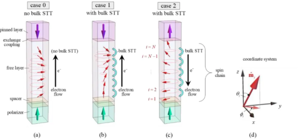
In this work, we consider from a theoretical and numerical standpoint the operation and properties of all-perpendicular spin-valve STNOs where a DW is formed in the free layer under the application of an electric current. . The system is comprised of a multilayer stack consisting of a polarizer, nonmagnetic spacer layer, magnetically soft free layer, and pinned magnetic layer (Fig. 1a). The polarizer and pinned magnetic layers are assumed to have strong perpendicular magnetic anisotropy and considered fixed in these discussions. An electric current applied perpendicularly through the stack drives the oscillator dynamics in the free layer. An alternative three-terminal device involving a nonmagnetic heavy-metal layer at the base of the free magnetic layer is also discussed.
In the sections to follow, we first demonstrate the operation of the STNO in three regimes. Then, we present a reduced-complexity computational model and describe the observed dependence of the oscillation frequency on the applied electric current, the structural and material properties of the free layer, and the spin polarization factor for different operating configurations of the STNO. We finally examine and discuss the underlying physics responsible for the unique dynamical response of DW-based spin-valve STNOs, including reference to the nature of the competition between the participating interactions and the role of DW twist. Further details are also given in the Supplementary Material.
II. STRUCTURAL CONFIGURATION AND OPERATION
We consider three cases of operation illustrated in Figs. 1a-c. Depending on the directions of applied current and pinned layer magnetization, and whether bulk STT is negligible (case 0; Fig. 1a) or appreciable (cases
Figure 1: Schematic illustration of an all-perpendicular spin valve in the three cases considered: (a) case 0, (b) case 1, (c) case 2. In cases 0 and 1, the polarizer and pinned layer magnetizations are oppositely oriented and electron flow is in the direction from polarizer to pinned layer. In case 2, the magnetizations of pinned layer and polarizer are equally oriented, and the electron flow is in the reverse direction. In case 0, the electron flow within the bulk of the free layer is not spin polarized, while in cases 1 and 2 it is. The free layer magnetization is modeled as a chain of spins, with the
adopted spin-numbering scheme shown in Fig.1c. Figure1d shows the coordinate system with
respect to which the direction of each spin iis represented in terms of the polar and azimuthal angles,
i
3
1 and 2; Figs. 1b, c), strikingly different frequency responses are obtained (Figs. Erreur ! Source du renvoi
introuvable.a-c), with particularly surprising and atypical frequency-current characteristics observed in
cases 0 (Fig. 2a) and 2 (Fig. 2e). Frequency results in Fig. 2were obtained by simulating the magnetization dynamics of the free layer based on the spin-chain model outlined in section III (calculation details can be found in the Appendix).
Figure 2: (a-c) Frequency as a function of applied current for cases 0, 1, and 2 (Fig. 1a-c). (d-f) Corresponding spin configurations during steady-state precession about the vertical axis for several illustrative current values. (Spin valve not drawn to scale for convenience of illustration. Geometrical and material parameters are given
in the main text. Conversion from current amplitude to current density for all cases: 0.025 mA ↔ 108 A/cm2.)
In all cases considered (Figs. 1a-c), upon application of electric current, the spins of the itinerant electrons flowing through the spacer layer interact with the local magnetic moment of the polarizer and free layers, causing a transfer of angular momentum between them. This is known as the STT effect7, 8, 11. Because it is local in nature, occurring primarily at the interfaces of the magnetic and spacer layers, it is referred to as
4
the interfacial STT effect. As discussed later, the bulk STT effect9, 10 also has an important role in the STNO operation.
For electron flow from the polarizer toward the free layer (cases 0 and 1; Figs. 1a and b, respectively), the resulting interfacial STT tends to orient the magnetization of the free layer in the direction of the polarizer magnetization. Conversely, for electron flow in the opposite direction (case 2, Fig. 1c), the interfacial STT tends to orient the magnetization of the free layer in the direction opposite to that of the polarizer magnetization. In all cases, the tendency is for a DW to be introduced into the free layer from the end adjacent to the polarizer.
In case 0 (Fig. 1a), as the current is initially increased, the magnetization of the free layer cants due to the action of the interfacial STT, and precession begins about the pinned-layer interlayer exchange field with a frequency that is positively correlated with current (inset of Fig. Erreur ! Source du renvoi
introuvable.a). For sufficiently large currents, a DW is introduced into the free layer (Fig. Erreur ! Source du renvoi introuvable.b-iii) and moves up toward the pinned layer as current is further increased.
Remarkably, a maximum precessional frequency is eventually reached (Fig. Erreur ! Source du renvoi
introuvable.a-iv), at which time the DW is closest to the pinned layer (Fig. Erreur ! Source du renvoi introuvable.b-iv). Further increases in current results in a reduction of precessional frequency and a
downward movement of the DW away from the pinned layer. The frequency asymptotically approaches zero (Fig. Erreur ! Source du renvoi introuvable.a) and the DW position converges to the midpoint of the free layer (Fig. Erreur ! Source du renvoi introuvable.b-v) as I .
In cases 1 and 2 (Figs. 1b and c), when the spin polarization of the electric current within the bulk of the free layer is non-negligible there is an additional bulk STT exerted within the free magnetic layer due to the interaction between the spin-polarized current and the spatially varying local magnetic moment9. The primary action of the bulk STT is to push the DW in the direction of the electron flow10.
In case 1 (Fig. 1b), the bulk STT drives the DW toward the pinned layer, against which it is progressively compressed as current is increased. Since the interlayer exchange torque, which generates the precession, is larger when the DW is more compressed against the pinned layer, and because the in-plane component of the free-layer net magnetic moment (precessional inertia) is smaller with greater DW confinement (Fig.
Erreur ! Source du renvoi introuvable.e), more rapid oscillations are observed at larger current (Fig. Erreur ! Source du renvoi introuvable.b).
Conversely, in case 2 (Fig. 1c), the bulk STT pushes the DW in the reverse direction, toward the polarizer. For relatively low currents, precession is driven by the interlayer exchange torque supplied by the pinned layer (top), hence precession in the CCW direction (f 0), as can be inferred from the pinned-layer magnetization orientation. As the current is raised, the frequency of precession reduces, reaching zero (static equilibrium) for a certain current value (Fig. Erreur ! Source du renvoi introuvable.c). With a further increase in current, precession begins again, but now in the opposite, CW direction (f 0), with f positively correlated with I.
In all cases, under constant current, the system converges to a solution characterized by a steady-state precession of the DW magnetization about the vertical axis at some given frequency. The frequency-current relationships observed for the three cases (Fig. Erreur ! Source du renvoi introuvable.) can be understood in terms of the competition between the participating torques (Figs. 3, 4, and 5) and the twist of the spin chain that develops in case 0 and case 2, but not in case 1 (Fig. 6). The interplay between interfacial STT, bulk STT, interlayer exchange, and magnetocrystalline anisotropy, discussed here in the context of STNOs,
Code de champ modifié
Code de champ modifié Code de champ modifié Code de champ modifié
5
may be additionally relevant to STT-MRAM designs employing elongated storage layers, which have recently been proposed as a route to enhancing lateral scalability of memory cells to sub-10nm scale66-68. Similar interactions are also expected to occur in analogous three-terminal systems involving a current path running horizontally through a non-magnetic heavy-metal layer connecting to the free layer in place of the polarizer-spacer duo55, 69-75. In such devices, the role of the interfacial STT would be replaced by that of the SOT deriving from the spin-Hall effect or broken inversion symmetry at the corresponding interface12-15.
III. ONE-DIMENSIONAL SPIN-CHAIN MODEL
A one-dimensional (1D) model is first employed to represent the STNO in simplified form and to gain a general understanding of the underlying physics controlling STNO response highlighted in Fig. 2. Within this model, the magnetizations of the polarizer and the pinned layer are fixed. All degrees of freedom of the magnetic system are thus solely associated with the magnetization of the free layer, which we model as a chain of spins (Fig. 1c). The dynamics of the chain of spins describing the free layer magnetization is governed by the Landau-Lifshitz-Gilbert equation, consisting of the precessional- and damping-torque terms, and extended by the interfacial current-induced torque term, either interfacial STT or SOT, and the adiabatic and non-adiabatic bulk-STT terms14:
eff, interface, bSTT, ˆ ˆ ˆ ˆ i i i i i i i d d dt
dt m m m H m τ τ . (1)In the equation above, mˆi denotes the unit direction vector of the ith spin in the chain, t (s) is the time,
1 1
(rad s Oe )
is the gyromagnetic ratio (taken as positive), and
(unitless) is the Gilbert damping constant of the free layer. The effective magnetic field exerted on spin i is denoted by Heff,i (Oe). It is equal to the sum of the applied magnetic field Happ,i, the bulk exchange field Hex,i, the interlayer exchange fieldHiex,i, and the magnetocrystalline anisotropy field Hanis,i, i.e.,eff,i app,i ex,i iex,i anis,i
H H H H H
. (2)
Here, we have excluded from considerations the Oersted field, estimating that its effect on magnetization dynamics is negligible considering the nanoscale size of the spin-valve structure that we model (see next section for spin-valve dimensions). We have also dropped the magnetostatic field in Eq. (1), to simplify the analysis of the interplay between interactions responsible for the observed STNO frequency-current characteristics (Figs. Erreur ! Source du renvoi introuvable.a-c), which are not qualitatively affected by dipolar coupling. Expressions for the fields in Eq. (2) are provided in the Supplementary Material.
The interfacial current-induced torque in Eq. (1), as the interlayer exchange torque, is exerted only at an end spin, specifically the bottommost spin (i 1), and is modeled as
interface,1FLˆ1 ˆ DLˆ1ˆ1ˆ
τ m p m m p
. (3)
The direction of the unit vector
ˆp
and the values of the prefactors
FL and
DL are determined by thespecifics of the mechanism responsible for the torque, device geometry, materials system, and magnetization configuration14. In the case of interfacial STT, the unit vector
ˆp
has the direction of the polarizer magnetization, i.e., pˆ
0 0 pz
withp
z1
. In case of SOT,ˆp
is in the plane of the6
referred to the Supplementary Material and elsewhere14. In our analysis, we explicitly consider the case of interfacial STT, i.e., τinterface,1τiSTT,1, and shall refer to it from this stage forward by this latter symbol.
The last term τbSTT,i in the dynamical Eq. (1) represents the bulk STT, which, unlike the interfacial STT,
is applied to all the spins of the spin chain . The bulk STT efficiency is considered zero in case 0 and non-negligible in cases 1 (Fig. 1b) and 2 (Fig. 1c). While the bulk STT generally consists of an adiabatic and non-adiabatic contribution, we neglect the latter contribution in the ensuing analysis, as its effect on the results was found to not be significant. In other systems, however, the non-adiabatic contribution can play a critical role9, 10, 76-78. The explicit expression for the bulk STT is provided in the Supplementary Material.
According to the first term in Eq. (1), the precessional torques due to the micromagnetic fields can be individually computed using
τ
m H
ˆ
. These torques, together with the interfacial and bulk STTs, are depicted in Fig. 3a. The net magnetic momentμ
net(emu)
of the free layer and the net individual torquesacting on it,
T
iSTT,T
bSTT,T
iex, Tdamp (emu/s), are schematically represented in Fig. 3b. Their computationis detailed in the Supplementary Material.
Several qualities of the involved torques should be pointed out, which can be deduced from their expressions given in the Supplementary Material. For a vertically magnetized polarizer, assuming that
FL
0
in Eq. (3) (reasonable assumption for all-metallic spin-valve devices), the interfacial STT has only a polar component, i.e., τiSTT,1
iSTT,1 1θˆ , where θˆ1
cos
1cos
1 cos
1sin
1 sin
1
is the unitFigure 3: (a) Schematic illustration of the torques acting on the bottommost (i = 1), interior (1 < i < N), and topmost (i = N) spin of the free layer. (b) Representation of the net magnetic moment of the free layer with the net torques exerted upon it. Generally, the directions and magnitudes of the torques depend on the STNO operational configuration (orientation of polarizer and pinned layer magnetization), the relative strengths of the interfacial and bulk STTs, and current amplitude (Fig. 5).
7
vector in the polar direction with respect to the first spin. Similarly, for a vertically magnetized pinned layer, the interlayer exchange torque acts only along the azimuthal direction with respect to the topmost spin, i.e., τiex,N
iex,NˆN, where ˆN
sin
N cos
N 0
. In case of a planar spin structure, the bulk exchange torque and the bulk STT have the form τex,i
ex,iˆi and τbSTT,i
bSTT,iθˆi, whereas in the presence of DW twist, i.e., for a non-planar spin structure, these torques have finite projections in both the polar and azimuthal directions, i.e., ex,i ex,iˆi ex,iˆi
τ θ and bSTT,i bSTT,iˆi bSTT,iˆi
τ θ . Finally, on the condition of a steady-state precession about the vertical axis, the damping torque on each spin must be along the local polar direction, i.e., τdamp,i
mˆidmˆi dt
damp,iθˆi. To clarify, in the formsτ
θ
ˆ
andˆ T
T , the scalar prefactors multiplying the unit vectors denote not vector magnitudes,
τ and T T, but rather the sign-inclusive component values,
τ θˆ andˆ
TT T . Such a notation
convention is used to avoid clustering of indices when possible.
It can be concluded that the net interfacial STT torque and the net interlayer exchange torque acting on the net magnetic moment
μ
net of the free layer can be written as TiSTTTiSTT 1θˆ and Tiex = TiexˆN. With respect to the net magnetic moment, however, these and remaining net torques take the general formnet ˆnet ˆnet
ˆ
= T T T
T μ θ
, where Tμˆnet denotes the radial component tending to increase or decrease
the magnitude of
μ
net
netμ
ˆ
net. Nevertheless, in specific cases, a given individual torque may have onlyone finite component, as illustrated below. Finally, we note that during steady-state precession about the vertical axis, when the magnitude
μ
net is unchanging, the vectorial sum of all net torques must be of theform TnetTiSTTTbSTTTiexTdampTnetˆnet, indicating a compensation of torque components, to be addressed in the coming analysis.
IV. STNO CHARACTERISTICS
A. In the absence of bulk STT: case 0
First, we consider current-induced DW oscillations in an all-perpendicular spin-valve structure in the absence of bulk STT (case 0, Fig. 1a). This provides a clearer understanding of the effects of the interfacial STT on oscillator dynamics and the coupling between the polar and azimuthal degrees of freedom of the spin chain. The bulk STT can generally be neglected when the spin polarization of the electric current passing through the free layer is sufficiently small. A heterostructured free layer, for example, can be optimized for large STT near the free-layer/spacer interface and reduced STT within the bulk through appropriate materials selection.
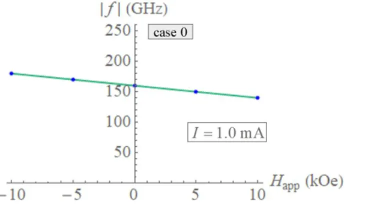
We assume the soft free layer to be perfectly soft, i.e., to have zero magnetocrystalline anisotropy. The operation of the considered STNO is analyzed in the absence of an applied magnetic field. Oersted and magnetostatic fields are excluded from the model. Since we are considering an all-perpendicular spin-valve structure, the polarizer and the pinned layer are taken to be magnetized vertically. We chose the former to be magnetized up, i.e., pˆ
0 0 1
, and the latter to be magnetized down, i.e., qˆ
0 0 1
. In the absence of bulk STT and for a symmetric interfacial-STT efficiency Eq. (A5), the response of the modeled STNO is identical regardless of the relative orientations of the polarizer and pinner-layer magnetizations.8
Figure 4:Illustrations of the competitions between local torques τi’s acting on an arbitrary interior
spin mˆi, and of net torques T ’s acting on the net free-layer magnetic moment μnet, during steady
9
By symmetry, we expect the precession of spins of the free layer under an applied current to be about the vertical axis, as illustrated in Fig. 1a.
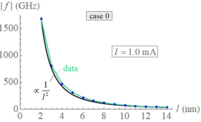
The free layer is modeled as a rectangular cuboid of length l 7 nmwith a square base of side length 5 nm
w . The free-layer exchange length, saturation magnetization, and damping parameter are chosen to be
A
ex1.0 μerg/cm
,3 s 800 emu/cm
M , and
0.02, respectively. The finite-differences cell size associated with each spin is 1 nm, henceN
l
7
spins discretize the free layer magnetization. The energy density of the interlayer exchange coupling between the free and pinned layers is set toJ
ex
2
A
ex
, which specifies an interlayer exchange coupling of the same strength as theexchange coupling between neighboring spins within the free layer. The device-specific constants in Eq. (A5) are chosen to be qp A 1 and
q
n
B
0
, so that
( )1. By numerically integrating theextended LLG Eq. (1), we obtain the dynamics of the spin chain describing the free-layer magnetization. Figure Erreur ! Source du renvoi introuvable.a shows the frequency of steady-state oscillations of the free-layer magnetization as a function of applied current. Electron flow in the direction from polarizer toward to the pinned layer is regarded as positive current in the present case.
At zero applied current, the system is in a stable equilibrium state with the free-layer magnetization oriented in the direction of the pinned layer (Fig. Erreur ! Source du renvoi introuvable.d(i)). The bulk and interlayer exchange energies are both minimum for this configuration. As the applied DC current is increased, the interfacial STT acts to tilt the bottommost spin of the free layer in the direction of the polarizer magnetization, i.e., counter to the magnetization of the pinned layer (Fig. Erreur ! Source du renvoi
introuvable.d (ii)), provided there is a small perturbation of the bottommost spin that directs it away from
its perfect alignment with the magnetization of the polarizer. With initial tilting of the first spin, the remaining spins in the chain tilt as well, owing to the bulk exchange interaction. As a result, a finite angle
q
N
develops between the last spin iN in the chain and the magnetization direction of the pinned layer ˆq. The finite angle
Nq implies an interlayer exchange torque exerted by the pinned layer on the free layer.This torque, received by the topmost spin of the chain, is distributed over the remaining spins via the bulk exchange interaction and generates the precession of the free-layer magnetization as a whole.
Simulations show that the magnetization oscillations persist only if a current is applied in excess of a threshold value, which, for the specified STNO, is
I
th0.02 mA
. ForI
I
th, the precessingmagnetization relaxes back to its perfectly vertical equilibrium configuration (Fig. Erreur ! Source du
renvoi introuvable.b(i)), regardless of the magnitude of the perturbation. A finite threshold current for
sustained magnetization oscillations is a common feature of many STNO devices29, 40, 79.
From the above considerations, it is reasonable to expect that an increase in applied current leads to an increase in the angle
Nq between the topmost spin and the pinned-layer magnetization, and hence resultsin a greater interlayer exchange torque, implying faster precession. For relatively low currents, this is indeed the case, as implied by the initial positive correlation between the absolute frequency and applied current shown in the inset of Fig. Erreur ! Source du renvoi introuvable.a. Surprisingly, with greater increases in applied current, the frequency begins to level off and subsequently decrease (inset of Fig. Erreur !
Source du renvoi introuvable.a), approaching asymptotically zero in the high current limit, i.e., f 0
10
As noted, for zero applied current, the free-layer magnetization is stationary, with all spins oriented along the direction of the pinned-layer magnetization, i.e.,
i
0
, for all i. As the current is initially increased,the spins tilt, and the polar angle of each spin becomes finite, i.e.,
i
0
. Simulations show that the twistingof the spin chain for sufficiently reduced current is relatively small, hence we can regard the spin chain as being approximately structurally planar at low currents. In this case (Fig. Erreur ! Source du renvoi
introuvable.a,d(ii)), the azimuthal directions are nearly the same for all spins, i.e.,
net 1 2
ˆ ˆ ˆ ... ˆ N
. Furthermore, the polar directions of all spins for low currents are mutually comparable as well, i.e., θˆnetθˆ1θˆ2 ... θˆN. We, therefore, conclude that at low current bias, the interfacial STT, TiSTTTiSTTθˆnet, which acts in the ˆθnet direction, is balanced by the damping torque,
Figure 5: (a-c) Azimuthal and (d-f) vertical projections of the net interlayer exchange, interfacial spin-transfer, and damping torques, and the resultant net torque acting on the net free layer magnetic moment in cases 0, 1, and 2, given as a function of applied current. The azimuthal torque components drive STNO oscillations, while the vertical torque components mutually compensate for steady-state magnetization precession.
11 dampTdampˆnet
T θ
, of opposite sense, so as to result in steady-state precession of the spin chain about the vertical axis, i.e.,
iSTT damp 0 (for low currents)
T T
. (4)
The situation described by the equation above is analogous to that characterizing many previously proposed STNO designs3, 34, 39, 80, 81. The interlayer exchange torque, TiexTiexˆnet, acting in the azimuthal direction
net
ˆ
, consequently, generates alone the precession of magnetization in the low current regime. Since, according to Eq. (A11),
T
iex0
for a downward-oriented pinned-layer magnetization (q
z1
), themagnetization precession of the free layer in the case considered is in the CW direction.
For a larger current bias, a twist in the spin chain becomes prominent (Fig. 4a(i) (shadow), Fig. 6a,d) and Eq. (4) no longer holds. That the spin chain necessarily features a twist during steady-state oscillations can be recognized by inspecting the conditions for steady-state precession of any interior spin of the chain (Fig. 4a(i)). If the spin chain is undergoing steady-state precession about the vertical axis as a whole, then each spin must be undergoing steady-state precession about the same axis individually. The damping torque,
damp,i
ˆidˆi dtτ m m
, acting on an arbitrary interior spin i, consequently, acts in the θˆi direction in the case of steady-state CW precession about the vertical axis. For such precession to be possible, there must be an equal and opposite torque to balance τdamp,idamp,iθˆi. In our reduced complexity model, this torque could only come from the bulk exchange interaction, provided there exists a twist in the spin chain to generate it. A twist in the spin chain, therefore, is a necessary condition for steady-state precession of the free-layer magnetization in case 0.
To restate the physics in simple terms, the nonuniform fanning of the spin chain (which specifies the
-profile) results in an uncompensated, azimuthal component of the bulk exchange torque, ex,i ex,iˆi
τ
, on each interior spin, which generates its precession about the vertical axis, whereas the twisting of the spin chain (which specifies the
-profile) gives rise to the polar component of the bulk exchange torque,ex,i ex,iˆ
τ θ
, needed to balance the damping torque, τdamp,idamp,iθˆi, so that steady-state precession is achieved.
12 In the continuum limit, a finite ex
τ
implies a non-vanishing second derivative of the polar angle
( )z , whereas a finite ex
τ
implies a non-vanishing first derivative of the azimuthal angle
( )z with respect to the longitudinal coordinate z50. Since the rate of precession and, consequently, τdamp initially increasewith current, the counterbalancing torque component ex
τ
must also increase for steady-state precession to
Figure 6: (a-c) The azimuthal angle difference, N1, between the topmost and the bottommost free-layer
spin as a function of applied current for cases 0, 1, and 2. The angle difference reflects the twist in the spin chain, which monotonically changes with applied current in cases 0 and 2, while it is absent in case 1. (d-f) An overhead view of the free layer spins at a given current showing the developed twist in the spin change. (A careful comparison of the positions of the arrow tips with respect to their circular traces reveals that in case 0
1 45 N
13
persist at larger applied current. This implies increased twist at larger current amplitudes and oscillation frequencies (Fig. 6a).
Since the azimuthal direction ˆi
sini cosi 0
of each spin is substantially different in the presence of prominent twist, Eq. (4) no longer holds, as it was based on the approximation of structural planarity of the spin chain. Figure 4a(iii) demonstrates that the net interfacial STT, TiSTTTiSTT 1θˆ , is no longer in balance with the net damping torque, Tdamp, since the two torques in the presence of prominent twist have significantly different directions.Along the vertical direction, the net damping torque, Tdamp, is still compensated by
T
iSTT (Figs. 4a(iii) and5d), so that steady-state precession is realized:
iSTT damp 0
z z
T T
(5)
The net torque generating the precession of the twisted spin chain, therefore, is equal to the vectorial sum of the interlayer exchange torque,
T
iex, and the uncompensated component of the interfacial STT,iSTT damp
T T
. The uncompensated STT component given by the latter sum is necessarily an in-plane component, such that the net torque
net iex iSTT damp
T T T T
(6)
is along the azimuthal ˆnet direction of the net magnetic moment
μ
net, i.e., TnetTnet netˆ , as required for steady-state precession about the vertical axis (Fig. 4a(iii)).As can be seen in Fig. 4a(iii), the in-plane component of the net interfacial STT projects negatively onto the azimuthal component of the net interlayer exchange torque, thus exerting a braking action that slows down the precession of the free-layer magnetic moment. Geometrically, as the twist increases with increasing current (Fig. 6a), the net interfacial STT orients more in the direction opposite to that of the net interlayer exchange torque, bringing about a reduction of oscillation frequency with increasing current, as observed in Fig. Erreur ! Source du renvoi introuvable.a for high current values. The competition between the azimuthal components of the net torques and the compensation of their vertical components is shown in Figs. 5a and 5d.
In the limit I the oscillation frequency is observed to approach zero (Fig. Erreur ! Source du renvoi
introuvable.a). This implies static equilibrium in the high-current limit. Such an equilibrium is only
possible on condition that Tnet0. Indeed, as simulations reveal, the azimuthal-angle difference between
the first and last spin in the twisted chain approaches 90 in the given limit, i.e.,
N
190
as I (Fig. 6a). According to Eqs. (A10) and (A11), in this limit, the interfacial STT tends toward an antiparallel alignment with the interlayer exchange torque, as shown in Fig. 7, which results in torque cancellation (
net
0
T
, f 0).It can be intuitively argued that in the high current limit steady-state oscillations cannot persists in case 0. Namely, when I , we expect that mˆ1
0 0 1
on account of an infinitely coercive interfacial STT. A vertically oriented spin, however, cannot precess about the vertical axis, as it possesses no in-plane14
component; hence, it cannot transmit power to the neighboring spin in the chain through the exchange interaction.
In effect, the limiting condition I is equivalent to the condition of a vertically fixed bottommost spin. Since the magnetic moment of the pinned layer is also vertically fixed, the system reduces to a string of spins with vertically fixed ends, a basic micromagnetics boundary-value problem with a well-known equilibrium solution. This solution consists of a DW centered at the midpoint between the two boundaries, with no twist and a constant rate of change of the polar angle
along the direction of the string of spins,i.e., uniform fanning82. This is precisely the solution obtained by our simulations for the spin valve in the
high current limit (Fig. 2d(v)), where the
N
190
difference between the first and last spin of thechain in the high-current limit is reconciled with the no-twist solution of the basic micromagnetic boundary-value problem by virtue of the fact that the first (bottommost) spin of the spin chain has a vanishing in-plane component, i.e.,
1
0
as I . As Fig. 6d shows, even for a relatively low current, the twistingof the spin chain is concentrated near the bottom of the free layer where the spins are largely vertically oriented, so the twist is not very noticeable. In the continuum limit (N ), when I , the twisting is confined to an infinitesimally small region at the base of the free layer, and since
(z 0) 0, the overall spin configuration can equivalently be regarded as having no twist.Considering that steady-state precession in case 0 depends sensitively on the azimuthal angle difference
1
N
, which is highly affected by fluctuations of spin direction, we expect considerable spectral linewidth broadening in the presence of thermal agitation of the spins due to finite ambient temperature and Joule heating. The stochastic fluctuations of the direction of the bottommost spin of the free layer imply not only fluctuations of the interfacial-STT magnitude, but also its direction. A drastic effect of thermal fluctuations is expected at larger currents, when the bottommost free-layer spin is mostly vertically orientedFigure 7: Illustrations of the net magnetic moment of the free layer, μnet, and the torques acting on it in
case 0 when I . In the high-current limit, the net interfacial STT, TiSTT, counterbalances the action
of the net interlayer exchange torque, Tiex, thus bringing the system into a state of static equilibrium. As
Fig. 6a shows, the twist in the spin chain (which in the considered limit is confined to the bottommost
region of the free layer) approaches 90 , and thus, according to (A10) and (A11), TiSTT tends toward an
15
(
1
0
) andT
iSTT is large. Under such conditions, a very small fluctuation of the spin’s direction can resultin a diametrical change of the torque’s orientation. Since
T
iSTT drives oscillations by forcing a DW into thefree layer wherein it precesses about the interlayer exchange field, and modulates the precessional frequency through its braking action, thermal fluctuations at larger currents theoretically are expected to highly impact the oscillator’s dynamical response in case 0.
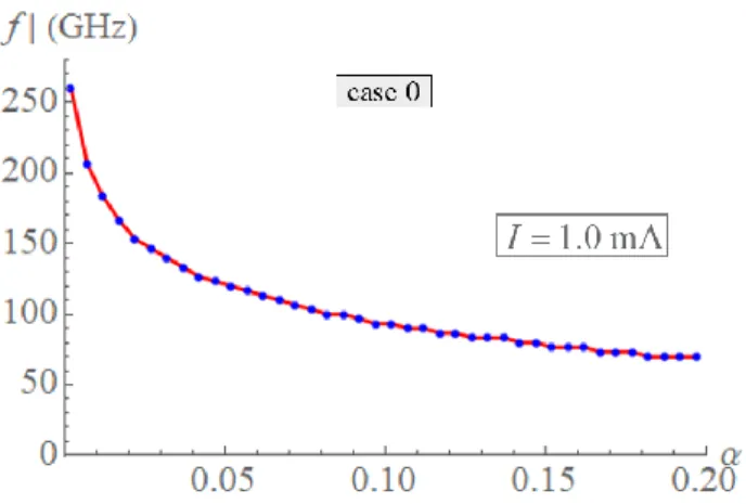
It must be noted, however, that for the present STNO specifications, a current of I 1 mA, closely matching the amplitude at which the frequency of oscillations is maximum (Fig. 2a), corresponds to a current density of
9 2
2.78 10 A/cm
j
, which exceeds by roughly two orders of magnitude thebreakdown threshold for typical spin-valve devices. It would, therefore, be experimentally difficult to study the oscillator response in the high-current regime in case 0, as the device would likely not be able to withstand the extreme conditions of operation. Exploring the physics of the frequency dependence on current in case 0, nonetheless highlights the competition between the participating torques and the role of DW twist, which is particularly useful in explaining the behavior of the STNO under case-1 and case-2 operating conditions discussed in the subsequent sections.
The effects of damping and other material and structural parameters on the STNO dynamical response in case 0 are presented in the Supplementary Material.
B. In the presence of bulk STT: cases 1 and 2
We investigate the current-frequency characteristics of a spin valve of the same structural and material properties as described previously, except now we consider the current passing through the free layer to be spin polarized by setting, for the first set of simulations, P 1 in Eq. (A7). This leads to the emergence of the bulk STT, which distinctly affects the STNO response. Later we shall inspect the dependence of the
-f I characteristics on the value of the spin polarization P. To simplify analysis, we shall ignore non-adiabatic effects, and thus impose
0 in Eq. (A6). (Simulations with
~ indicated that the non-adiabatic effects on dynamics of our oscillator were not significant.)Figures 2b and 2c show that in the presence of bulk STT, the f I- characteristics of the modeled STNO are qualitatively different for the two considered operating configurations, i.e.: (case 1) when the magnetic moments of the polarizer and the pinned layer are oriented antiparallel to each other (Fig. 1b), and (case 2) when they are oriented parallel to each other (Fig. 1c). To induce oscillations, the electric current in case 1 must be applied so that electrons flow from the pinned layer toward the polarizer, while in case 2, the electric current should be applied in the opposite direction; otherwise the applied current stabilizes the spins in a static vertical configuration.
Case 1
The bulk STT tends to translate a DW in the direction of the electron flow. In case 1, the spin current passing through the free layer pushes the DW against the pinned layer, causing it to compress (Fig. 2e). This compression of the DW results in an increased bulk exchange torque in the azimuthal direction, and hence increased rate of precession47, 50. Since the DW cannot exit the free layer at the top interface because the pinned-layer magnetization is fixed, increased current inevitably implies increased DW compression and greater oscillation frequency (Fig. 2b).
16
Simulation results presented in this section where obtained using a spin-chain model consisting of N 21 spins (cell size 0.33 nm) in order to resolve the spatial magnetization variation associated with DW compression against the pinned layer in case 1 (Fig. 2e).
To reach a deeper understanding of the interplay between the different participating interactions resulting in steady-state precession in case 1, we inspect the balance of torques necessary for the steady-state precession of an arbitrary spin interior to the free-layer spin chain. In Fig. 4b(i), we see that the bulk STT,
bSTT,i
bSTT,iˆiτ θ
, responsible for pushing the DW toward the direction of the pinned layer, acts counter to
the damping torque, τdamp
dampθˆi. Simulation results confirm that these two torques indeed compensate one another for each interior spin of the chain during steady-state precession, i.e., τbSTT,iτdamp,i0, for all i. A twist in the spin chain, therefore, is not a necessary condition for steady-state precession in the presence of bulk STT for the considered configuration (case 1, Fig. 4b(ii)), as the damping torque τdamp,i is already balanced at each interior spin by τbSTT,i.Simulations confirm that a twist does not develop during steady-state oscillations in case 1 (Fig. 6b). Still, as in the absence of bulk STT (case 0, Fig. 4a(i)), it is the bulk exchange torque, τex,i
ex,iˆi, arising from the nonuniform fanning of the spins that generates the precession in the azimuthal direction internally.Externally, as required for steady-state precession about the vertical axis, the vertical components of the torques acting on the net magnetic moment balance (Figs. 4b(iii) and 5e),
iSTT bSTT damp 0
z z z
T T T
. (7)
The net torque, equal to the vectorial sum
net iex iSTT bSTT damp
T T T T T
, (8)
acts, in consequence of Eq. (7), in-plane and orthogonal to
μ
net, i.e., in the azimuthal ˆnet direction, thus generating precession of the net free-layer magnetic moment about the vertical axis. Schematically this is illustrated in Fig. 4b(iii).Figure 5b shows that for large enough applied currents, the interfacial STT is negligibly small in comparison to the remaining torques in equation Eq. (8). This can be expected in view of the near-perfect vertical orientation of the bottommost spin (i 1) for such operating conditions. Under such conditions, the described spin valve responds equivalently to the STNO investigated by Franchin, et al.50, involving a free layer pinned at both ends, and an absence of interfacial STT. The authors have analytically determined the
-f I characteristics for such a system in the low and high current regimes. Our simulations similarly show that for large current amplitudes the frequency is proportional to the square of the current, i.e.,
2
f I .
For a discussion of the dependence of frequency on the damping constant and other material and structural parameters, see the Supplementary Material.
17
Case 2
Qualitatively very different f I- characteristics are obtained for case 2, when the polarizer and pinned-layer magnetizations are oriented in the same direction, and the electrons stream from the pinned pinned-layer toward the polarizer. For convenience, we shall redefine here positive current to correspond to electron flow from the pinned layer toward the polarizer. Simulations of spin-chain dynamics in case 2 were obtained using a spin chain involving N 14 spins (cell size 0.5 nm). Figure 2c shows for the described operating configuration a threshold current of
I
th0.05 mA
required for sustained CCWmagnetization precession. From this mark (f 40 GHz), the oscillation frequency is seen to gradually decrease to zero with increasing current amplitude, at which point the DW magnetization ceases to precess (f 0). As current is increased further, precession commences again, but now in the opposite CW direction (f 0).
For the material and structural specifications of the STNO described, the current amplitude at which static equilibrium is reached (
I
00.5 mA
; Fig. 2c) in case 2 corresponds to a current density of9 2
0 1.4 10 A cm
j , which well exceeds the typical spin-valve breakdown threshold. It would not be straightforward, therefore, to experimentally explore the STNO response within a current range inclusive of
I
0. Yet, we do not dismiss the possibility that certain modifications to STNO specifications may resultin a sufficient reduction of the transition current,
I
0, that would make experimental investigation of theoscillator response within its vicinity feasible. Explaining the unique frequency-current characteristic shown in Fig. 2c, in any event, proves to be useful in broadening our understanding of the nature of possible torque competitions in spin-valve devices featuring a DW.
For a deeper insight into the physics responsible for the atypical oscillator behavior illustrated in Fig. 2c, we turn our attention to the torques exerted on an arbitrary interior spin within the free-layer spin chain. For low current values, precession of the net magnetic moment is predominantly due to the interlayer exchange torque supplied by the pinned layer (Fig. 5c). Since the pinned layer in case 2 is oriented upward, the precession is initially in the CCW direction (or sense) when viewed from the top. The sense of magnetization precession specifies the orientation of the damping torque, τdamp,i
mˆidmˆi dt, whichis proportional to the first time-derivative of the magnetization.
Figure 4c(i) illustrates the torques acting on an arbitrary interior spin when the magnetization precession is in the CCW direction. For current values giving rise to CCW precession, the damping torque is oriented in the θˆi direction. The polar component of the bulk STT, bSTT,i
τ
, is also oriented in the θˆi direction, as it tends to propel the DW in the direction of the electron flow, i.e., toward the polarizer. These two torques,
damp,i
damp,iˆiτ θ
and bSTT,i
τ
, therefore, constructively superimpose. Yet, we know that for steady-state precession the resultant polar torque on each spin must vanish. We thus conclude that a twist in the spin chain is a necessary condition for steady-state CCW precession in the presence of bulk STT in case 2, so that torque compensation in the polar direction is achieved, i.e., damp,i bSTT,i ex,i
τ τ τ 0 , where ex,i τ is the polar component of the bulk exchange torque arising from the twist. Furthermore, we conclude that the
18
sense of the twist is such that the bottommost spin leads in the CCW precession of the spin chain, i.e.,
1 2
...
N
, so that ex,i
τ
is oriented opposite to the remaining two torques, τdamp,i and bSTT,i
τ . Simulations confirm the presence of twist in the spin chain during steady-state CCW precession in case 2 (Fig. 6c,f).
The twist, which is a necessary condition for steady-state precession in the presence of bulk STT in case 2, implies the existence of a finite azimuthal component of the bulk STT, bSTT,i
τ
. For the particular sense of twist inherent to steady-state CCW precession in case 2 (Fig. 6c), bSTT,i
τ
is oriented counter to the azimuthal component of the bulk exchange torque, ex,i
τ
, resulting from the nonuniform fanning of the spins. Consequently, the azimuthal component of the bulk STT, bSTT,i
τ
, whose magnitude is monotonically increasing with applied current, exerts a breaking action upon the CCW precession of the free-layer magnetization.
With increasing current and twist, the azimuthal component of the bulk STT, bSTT,i
τ
, acting on each internal spin i, grows in magnitude, ultimately counter-balancing the azimuthal component of the bulk exchange torque, ex,i
τ
. At compensation, i.e., ex,i bTT,i
τ τ 0
, static equilibrium is reached, hence
f I
( )
0
0
, forsome particular current value
I
0 (Fig. 4c(i)). With further increases in current, bSTT,i τ overcomes ex,i τ , i.e., bSTT,i ex,i
τ
τ
, and precession commences again, but now in the opposite, CW direction.
Figure 4d(i) shows the torques acting on an interior spin when
I
I
0, i.e., in the case of CW precession,where bSTT,i ex,i
τ
τ
. The damping torque, τdamp,i , being proportional to the time-rate of change of the
spin direction vector
m
ˆ
i, changes orientation with the change of the sense of precession, and hence is nowin the direction counter to the polar component of the bulk STT, bSTT,i
τ
(Fig. 4d(i)). Since the twist of the spin chain increases continuously as the current approaches
I
0 from below, it does not undergo a suddenchange in sense as the current crosses
I
0. Consequently, the azimuthal components of the bulk STT, bSTT,i
τ , and the bulk exchange torque, ex,i
τ
, do not change orientation upon the transition from CCW to CW precession. Simulation show that the twist continues increasing linearly as current is increased beyond
I
0(Fig. 6c).
From the viewpoint of net magnetic moment (Figs. 3c(iii) and 4d(iii)), the vertical components of the net torques balance, as expressed in Eq. (7), while the resultant torque
T
net , given by Eq. (8), necessarily actsin the ˆnet direction, thus generating magnetization precession about the vertical axis, similarly as in case 1. However, unlike in case 1, the magnitude of
T
net is not monotonically increasing with current, as impliedby the f I- characteristic shown in Fig. 2c, and as observed in Fig. 5c.
The main contribution to
T
net, whenI
I
0, comes from the interlayer exchange torqueT
iex, as seen in19
in the CCW direction when viewed from the top, according to Eq. (A11). Figures 4c(iii) and 5c show that the bulk STT,
T
bSTT, countersT
iex along the azimuthal direction. With increasing current,T
bSTTincreasingly exerts a braking action on the magnetization precession, ultimately causing it to stop (f 0) at
I
I
0.When the applied current I exceeds
I
0, the azimuthal component ofT
bSTT overcomes the azimuthalcomponent of
T
iex, and precession commences again, only now in the opposite, CW direction when viewedfrom the top (Fig. 4d(iii)).
Neither for
I
I
0 (Figs. 4e(iii)) nor forI
I
0 (Fig. 4d(iii)) is the azimuthal component of the interfacialSTT,
T
iSTT, or the damping torque, Tdamp, comparable to that of the azimuthal components ofT
iex and bSTTT
(Fig. 5c). This remains so even for very large current,
I
I
0, when the magnitude ofT
iSTT issubstantial. This is because in case 2, the bottommost spin adjacent to the polarizer layer is oriented almost entirely in-plane (Fig. 2f), and hence
T
iSTT ( m
ˆ
1) is almost perfectly vertical, i.e., it has no appreciablein-plane (azimuthal) component.
The half-DW-like spin configuration of the free layer observed in case 2 (Fig. 2f) reflects the competition between the interfacial and bulk STTs in displacing the magnetization nonuniformity within the free layer in the vertical direction: the interfacial STT tends to drive a DW into the free layer, while the bulk STT works to expel the DW at the bottom end of the free layer by pushing it downward, in the direction of the electron flow.
A discussion of the influence of damping and other STNO parameters on STNO response is provided in the Supplementary Material.
V. CONCLUSION
We investigated the spin-transfer-driven oscillations of a transverse domain wall confined to an all-perpendicular spin-valve structure using a 1D micromagnetic model. The response of the STNO under three operating conditions was considered: (case 0) in the absence of spin polarization of the electron flow within the free layer (i.e., in the absence of bulk STT), and (cases 1 and 2) in the presence of bulk STT, when itinerant electrons flow from the polarizer toward the pinned layer (case 1), and when they flow in the opposite direction (case 2). It was found that the twist of the magnetization about the vertical axis of precession plays a key role in the operation of the studied STNO. It was shown that the twist develops as a necessary condition for steady-state oscillations about the vertical axis in case 0 and case 2. As discussed in the Supplementary Material, owing to this twist, the frequency of oscillations is virtually insensitive to the damping constant
of the free layer in case 2. This insensitivity is attributed to the nearly complete balance between the interfacial and the bulk spin-transfer torques in the vertical direction. Due to the competition between these two torques in the azimuthal direction, the precession of the free-layer magnetization is found to switch from CCW to CW as the applied current is raised beyond a certain compensation-point value.We showed the way in which the material and structural parameters influence the frequency of the STNO in the three cases considered and suggested how variations in the values of these parameters may affect the spectral linewidth (Supplementary Material). The highly atypical dynamical response of our STNO to
20
current for the three cases investigated and the different competitions that arise in each case between the acting torques suggest that the described STNO may be found useful for fundamental investigations of spintronic and magnetic phenomena at the nanoscale. The nature of the interplay between the exchange, STT, and damping torques, resulting in qualitatively different STNO characteristics obtained for cases 0-2 (Fig. 4a-c), suggests that introducing additional interactions, such as SOT or Dzyaloshinskii-Moriya interaction (DMI), in a confined current-driven system such as the one studied here, or extensions of it, may result in altered modes in which participating torque components cooperate in producing steady-state precession, which could sensitively affect STNO performance. Moreover, the dependence of twist on current, as observed in cases 0 and 2 (Fig. 6a, c), invites the question of how a spiral spin structure83-85 having inherent twist may interact with the spin-polarized current in the confines of a spin valve. The interaction between the two may result in the partial unwinding or further twisting of the magnetic structure, with a concomitant change in oscillation frequency. Exploring the operation of similar systems featuring additional interactions could thus reveal new possibilities for tailoring STNO response to current.The prospect of optimizing STNO response for reduced sensitivity to the damping constant, as indicated here, could have additional implications for spintronic-device engineering and related technologies.
While steady-state magnetization precession about the vertical axis in an all-perpendicular spin-valve structure, considered here, does not generate power output through the magnetoresistive effect, it does produce an oscillating stray magnetic field, which could be useful for microwave-assisted magnetic recording and for dipolar coupling between oscillators through the magnetostatic interaction. Alterations to the all-perpendicular STNO design, such as introducing a non-perpendicular anisotropy component to one or more of the layers41, 86-89, or extensions to the STNO geometry, such as a transformation to a three-terminal device90, 91, could be considered as a means for extracting microwave electrical signals from the oscillator, though such considerations are beyond the scope of the present work.
ACKNOWLEDGEMENTS
Work at UCSD was supported by Quantum-Materials for Energy Efficient Neuromorphic-Computing, an Energy Frontier Research Center funded by DOE, Office of Science, BES under Award DE-SC0019273. This work was also supported by the impact project LUE-N4S, part of the French PIA project “Lorraine Université d’Excellence”, reference ANR-15IDEX-04-LUE, and by the “FEDER-FSE Lorraine et Massif Vosges 2014-2020”, a European Union Program.
APPENDIX: Spin-chain model details: field and torque calculations
The exchange field within the 1D spin-chain model (Eq. (1)), is given by
ex ex, 2 1 1 s 2 ˆ ˆ i i i A M H m m (A1)where
A
ex(erg/cm)
is the exchange stiffness constant. The thickness (cm) denotes the portion of thelength of the free layer occupied by each spin, i.e., l N, where l is the free-layer thickness and N is the number of spins discretizing the free-layer magnetization. A numbering convention is adopted such that the free-layer spin adjacent to the polarizer is regarded as the first spin in the chain (i 1), while the
free-21
layer spin adjacent to the pinned layer is regarded as the last spin (iN). We account for the discontinuity of the free layer at the top and bottom interfaces via the imposition
m
ˆ
0
m
ˆ
N 1
0
.The interlayer exchange field is due to the ferromagnetic interlayer coupling between the free layer and the pinned layer. This field is exerted only at the boundary, specifically, upon the topmost free-layer spin (
iN), adjacent to the pinned layer. The expression for the interlayer exchange field is
ex iex, s ˆ i iN J M
H q (A2)where
iN is the Kronecker delta function,2 ex (erg/cm )
J is the interlayer exchange-coupling energy density, and ˆq is the unit direction vector of the pinned-layer magnetization.
The uniaxial magnetocrystalline anisotropy field for the ith spin is expressed as
u anis, s 2 ˆ ˆ ˆ i i K M H m k k , (A3) where 3 u (erg/cm )K and ˆk represent the free-layer magnetocrystalline-anisotropy energy density and the unit vector in the direction of the associated easy axis.
The interfacial STT, appearing in Eq. (1) as τinterface,i, is modeled by:
iSTT, 1 p 1 1 s ˆ ˆ ˆ ( ) 2 i i i j M e
τ m m p . (A4)Like the interlayer exchange interaction, the interfacial STT is a boundary effect, directly influencing only the first spin in the chain (i 1), hence the appearance of the Kronecker delta function
i1 in the expressionabove. Constants (erg s) and e (C) are the reduced Plank’s constant and the elementary electric charge. The electric current density is given by
2
(A/cm )
j
, while ˆp denotes the unit direction vector of the magnetization of the polarizer. The angular dependence of the STT efficiency is specified byp n 1p 1p 1p ( ) cos cos q q A B A B
. (A5)Here,
q
n,q
n, A, and B are device-dependent constants [ref., Xiao et al., 2005] and cos
1pm pˆ1ˆ. Inwords,
1p is the angle between the directions of the first spin in the chain and the adjacent polarizermagnetization.
The bulk STT contribution to the dynamics of the 1D chain of spins, appearing in Eq. (1), is expressed as
1 1 1 1 bSTT, ˆ ˆ ˆ ˆ ˆ ˆ ˆ 2 2 i i i i i i i i i u i i u i