DESIGN OF A SMALL ELECTRIC MOTOR DYNAMDMETER
By
Villiam A. Black Jr.
Submitted in partial fulfillment
of the requirement for the degree of Master of Science.
From The
Massachusetts Institute of Technology 1951
Author
Department of Electrical Engineering January 10, 1951
Thesis Supervisor
Chairman of Departmental Committee on Graduate Students.
6/
-7
Cambridge, Massachusetts January 10, 1951
Professor Gordon S. Brown
Chairman of the Graduate Committee Department of Electrical Engineering Massachusetts Institute of Technology Cambridge 39, Massachusetts
Dear Sir:
In accordance with the requirements for the degree of Master of Science, I submit herewith a thesis entitled "Design of a Small Electric Motor Dynamometer".
Respectfully,
William A. Black Jr. __ _
The author wishes to express his appreciation to Mr. Alexander Kusko for his advice and encouragement, to Mr. Charles O'Grady and Mr. L. A. Gould for their helpful suggestions, and to Mr. B. F.
Middleton for his assistance in construction of the dynamometer in
the student shop.
-CONTENTS
Page
ABSTRACT 1 SU... ... . .vi
CHAPTER 1 SUMMAR . . . 1
CHAPTER 2 INTRODUCTION
1. Measurement of Speed-Torque Characteristics
la. Loading of Electric Motors . . . .
lb. Torque Measurement . . . . . . lc. Speed Measurement ... 2. Method of Investigation . ... CHAPTER 1. 2. . ..
10
. . 10 3 PROCEDURE Dynamometer Specifications . . . . Dynamometer Design . . . . 2a. Electromechanical Dynamometer . . . .2b. Generator Current Controlling Circuit . . . ,
2co Speed-Control Voltage . . . .
CHAPTER 4 RESULTS
le Construction of Dynamometer ... 19
la. Cradled Generator . * * ... .. 19
Fig. 1. Photograph "Dynamometer Assembly" * * 24
Fig. 2. Photograph "Dynamometer Assembly" . . 25
Fig. 3. Dynamometer Cradle Construction Detail 26 lb. Speed Control Tachometer ... ... 20
lc. Control of Generator Armature Current . . . . 21 Fig. 4. Armature Current Control Circuit Diagrea27
Page
2.
Experimental Results . . . . ... 222as Constant Torque . . . . . . . . . 22
Fig, 5 Graph "Armature Current vs. Speed"n * . 28
Fig. 6 Grqph "Dynamometer Torque vs. Speed"n 29
2b* Constant Speed ... .... ... * * * ... * 23
Fig. 7 Graph "Dynamometer Torque vs. Speed" . . 30 Fig. 8 Graph "Tachometer Output vs. Speed" . * 31 2c. Driving Motor Torque . ... * * * ... 23 Fig. 9 Metering Diagram for Experimental Data 32
5 DISCUSSION OF RESULTS
Cradled Generator. . . . . Speed Control Tachometer . . . . Generator Current Controlling Circuit Driving Motor . . . . . . . . • . . . . . . . . • . • . . . . ". 33 . 35 • " 36
CHAPTER 6 RECOMMENDATIONS . . . 9 9 0 * . & 0
APPENDIX
Constant Torque Loading by an Induction Motor . . . . Fig. 1. Graph "Calculated Motor Torque vs. Motor Speed" Fig. 2. Graph "Calculated Motor Torque vs. Motor Speed"
with
"Combined Rotor & Stator Copper Losses" . . Fig. 3. Graph "Calculated Motor Torque vs. Motor Speed"
with
"Combined Rotor & Stator Copper Losses" . Fig. 4. Loading Devices . . . . Fig. 5. Electric Motor Speed-Torque Characteristics * * • CHAPTER 1. 2. 3.
4.
38 40 42 4346
~ _. ____ CL___Page
Fig. 6. Motor-Load Stability . . . . .
47
Sample Data Sheets .. ... . ... ...48
Bibliography .* • * *
•....
.• • *
0 &
49
IC-ABSTRACT
With the increased use of sub-fractional hp electric motors it has become necessary to further study the problems encouhtered in exp-erimentally determining speed-torque characteristics of electric motors. An electronically controlled dynamometer was designed -nd built which would provide accurate loadin, and accurate torque measurements of these small motors. A study of the dynamometer indicated that it can be used to accurately control the loading and to accurately determine the speed-torque characteristics of small electric motors if care is exercised in its construction and operation.
CHAPTER 1
S1IARY
It was desired to construct a dynamometer which would permit stable load-ing and accurate torque measurload-ing of sub-fractional hp electric motors when determining their speed-torque characteristics. An electronically
con-trolled dynamometer to fulfill this purpose was designed and constructed. Electronic control was applied to the dynamometer to permit accurate load-ing. A study of the completed electronically controlled dynamometer
in-dicated that it might be satisfactorily used to accurately test sub-fractional hp electric motors.
Design of the dynamometer was begun after a study was made of the pro-blems encountered in experimentally determining the speed-torque characteris-tics of electric motors. The testing methods employed at the present time,
the various speed-torque characteristics of electric motors that may be tested, and the various components that could be used in the dynamometer construction were included in the study.
The various testing methods used in experimentally determining the speed-torque characteristics of electric motors are presented in Chapter 2. Load-ing, torque measurLoad-ing, and speed measuring of the motor being tested are done in various ways. Loading is achieved by friction brakes, eddy current brakes, and direct-coupled generators. Torque measurement is done by spring balances, beam balances, torsion wires, and torque meters. Speed measurement is achieved through the use of direct coupled tachometers and slip counters, electronic tachometers, and calibrated variable frequency light sources. It was found
the testing procedures applicable for large and fractional hp electric motors are not necessarily applicable for testing sub-fractional hp elec-tric motors.
Chapter 3 presents the dynamometer specifications that should be met to provide stable loading of the various types of sub-fractional a-c and d-c electric motors, and to permit accurate torque measurements. These specifications are summarized as follows:
1. The dynamometer should provide stable loads for small induction motors, d-c motors, universal motors, and synchronous motors. 2. It should provide a convenient means of accurately measuring
the tested motor's running torque.
3. It should be capable of driving the motor being tested and provide a means of measuring the running torque when reverse-speed characteristics are needed.
4. It should be constructed with a minimum of components and with simplified controls so that maintenance and operation can be done quickly and conveniently.
A cradled generator was selected as the loading device in preference to a friction or eddy current brake because of its superior fulfillments of four specifications. An electronic powersupply was chosen to control the generator current, because of the ease of obtaining precise current control.
The results obtained from tests on the constructed dynamometer are presented in Chapter 4. The construction details and the operating charao-teristics were not exactly as expected, but the practicability of the
A tabulation of specific results are as follows:
1. An "Electric Motors Corp." d-c generator rated at 115 v.,
0o. amp., 7,000 rpm was cradled as the dynamometer.
2. An "Elnico Midget Rotation Indicator" rated at 110 v., 60 cycles, 1 phase was employed as the tachometer for t he feedback voltage.
3.
The generator armature current control circuit consisted of three 6L6 vacuum tube circuits in parallel, and one 6SF5 vacuum tube circuit acting as a d-c amplifier for the speed voltage error signal.4. Standard power panels found in the measurements and machinery laboratories at M.I.T. were employed as the power supply.
CHAPTER 2
INTRODUCTION
The loading of small electric motors and the measurement of their torque for testing purposes has been accomplished by many devices. Each device used in testing electric motors possesses certain advantages for particular motors, but the disadvantages have prevented universal application of any one device. Chapter 2 presents several widely used loading, torque measuring, and speed measuring devices used at the present time for test purposes, and points out their advantages and disadvantages. The important motor operating regions which could be
observed accurately by means of a correctly designed dynamometer are also presented.
1. Measurement of Speed-Torue Characteristics
The large increase in the use of small electric motors of 1/50 h.p. and less has made it necessary to measure their speed-torque character-istics in a practical, not tedious manner. Various means of measuring these characteristics may be found in text books, periodicals, and research papers.1 These methods, while practical for the larger elec-tric motors, are not necessarily applicable or exact in the speed-torque measurement of smaller motors.
A means to provide an easily adjustable, stable load on the tested motor through its operating range is the problem that presents
itself in the measurement of speed-torque characteristics. Various
1. See Bibliography for references, p. 49.
_~-Y--PI-_1-~-methods for loading and measuring the speed and torque of electric motors, aid the advantages and disadvantages of each are presented below,
la. Loading of Electric Motors
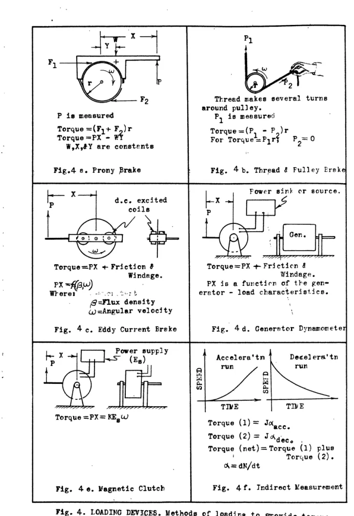
The prony brake or absorption dynamometer as a device of loading depends upon the surface friction between the brake lining and the drum attached to the motor shaft.1 The brake has a tendency to produce variations in the load, due to the change in friction between the brake band and the brake drum; the friction being a function of the normal forces on the drum, the coefficient of friction of the brake and drum, and the relative speed of the two surfaces. The brake can be used only as a power absorbing device and cannot be used to drive the motor when reverse-speed characteristics are needed. Loading of the motor being tested can be accomplished at low speeds and at zero speed, by the prony brake.
The thread-and-pulley brake, an adaption of the prony brake applied to small motors, consists of a spring balance, a thread, and a drum attached to the motor shaft.2 The tension of the thread around the drum is adjusted manually; the procedure is therefore tedious and perhaps inaccurate, especially if the operator does not hold his end of the thread at zero tension. As with the prony brake, the power
flow is unidirectional and the device cannot be used to drive the tested motor. Loading of the tested motor can also be accomplished from zero speed.
The eddy current brake provides a convenient means of adjusting
1. See fig. 4, Pc45,
L I ~
and maintaining a steady load from a steady d-c power supply. The brake consists of a disk attached to the tested motor shaft, and two or more d-c excited coils attached to a pivoted balance arm such that the magnetic flux produced by the coils will pass through the disk. Since the brake torque is a function of the air-gap flux density and the angular velocity of the disk, high loading at low
speeds can be accomplished only by a very high flux density. This re-quirement of a high flux density presents a serious limitation when loading is desired at near zero speeds. Low loads at high motor
speeds may not be possible with the eddy-current brake since the friction and windage loading of the rotating disk can become larger than the desired load. Friction and windage loading by the disk at high speeds, which is not measurable by the torque indicating device, can be taken into consideration by a graph of disk friction and windage losses vs. disk speed.
The electromechanical energy conversion loading device consists of a generator coupled to the tested motor.1 The generator is cradled as a dynamometer, and particular care must be taken to minimize the friction between the cradle and the generator frame if accurate torque measurements are to be obtained. The power output of the generator may be absorbed in a resistance load or it may be pumped back into the electrical system. As with the eddy-current brake, friction and windage losses by the generator rotor may be large at high speeds and thus may prevent light loads at high motor speeds. With small dynamometers employing brushes and commutators, the brush
1. See fig. 4, p. 45.
friction is relatively large. This brush friction can be the limit-ing factor in determinlimit-ing the minimum loadlimit-ing obtainable by such a dynamometer. An advantage offered by the direct-connected generator not offered by the aforementioned devices is that it can be used to drive the tested motor when reverse-speed characteristics of the tested motor are needed. Loading of the tested motor from zero speed may be possible with some generators, but usually only if auxiliary
control equipment is used.
The magnetic clutch, its characteristics varying considerably
with design, can be applied as a motor loading device. 1 All power input to the clutch is dissipated as heat through its walls, and thus it can be used only to absorb power from the tested motor and can not be used to drive it.
Indirect measurement of speed-torque of electric motors can be made from the slope of the speed-time curves of acceleration and deceleration runs of the motor if the motor-rotor inertia is known.2 Accurate measurements must be made in determining the speed and time simultaneously during the test run, in determining the rotor inertia, and in determining the slope of the speed-time curves if
consistent speed-torque data is to be obtained. This method of torque measurement is applicable where the motor shaft is inaccessible for direct coupling of a loading device.
lb. Torque Measurement
A spring balance actuated by a lever arm attached to the
frame of the loading device offers a convenient means of measuring 1. See fig. 4, p. 45.
2. See Bibliography, ref. #3, P-49 , and fig. 4, P-45.
---the motor torque. The balance may be obtained in various sizes;
calibration of the scales must be made periodically to assure accurate results.
A beam balance offers a more accurate means of measuring the motor torque than does the spring balance. The time consuming process
of balancing the scale is acceptable only where extreme accuracy in torque measurements must be made.
Torque may be measured directly by observing the angular defleo-tion of the tested motor mounted on a torsion wire, the axis of
which coincides with the spin axis of the rotor. Construction of the torsion wire mount can be tedious and costly, but for measuring very
small torques this disadvantage need not be important.
A torque meter has been designed which is connected between the shaft of the tested motor and the shaft of the load.1 Variations of a magnetic airgap, due to variations in shaft torque, unbalances a bridge network from which a calibrated meter reads torque directly. The advantage of such a meter is that motor shaft torque is measured at the motor shaft, and not through auxiliary equipment where torque losses occur. The torque meter was designed for measuring torques on large electric motors, however the design may be applicable to small electric motors. Measurement of torque is independent of the speed of the motor shaft, thus torque at and near sero speeds may be measured if leading of the tested motor is possible at low speeds.
lc. Speed Measurement
Direct-coupled tachometers and slip counters provide an
accurate means of measuring the speed of electric motors. These
speed-1. See Bibliography, ref. #14, p.
49,
8
measuring devices act as loads on the tested motor, and if the load presented by the tachometer or slip counter is appreciable compared to the motor load, it will be necessary to include their load as part of the friction and windage correction curve.1 If this is
not desirable and a generator dynamometer is used, it may be necessary to mount the tachometer or slip counter as an integral part of the dynamometer so that the torque of the speed measuring device will be measured by the torque measuring device.
Neon lights with variable-frequency source or a Strobotac offers a means of measuring the tested motor speed without creating a load on the motor. Small changes in speed can be measured only as accurately as the neon-light supply frequency is known, or as accu-rately as the calibrated dial of the Strobotac can be read. Their versatility, due to mobility and no loading, makes them suitable
for speed measurements of small electric motors. The manual operation of the neon lights and the Strobotac prevents their application for
speed measurement for control purposes, as would be necessary in feed-back control circuits.
Electronic tachometers have been designed for use where speed signals are needed for control purposes without the speed measuring device presenting a load on the driving motor. Their inaccuracy at low speeds in their present design does not make them applicable for wide ranges of speed.
1. The application of friction and windage correction curves has been presented in Section la under the eddy current brake.
9
2. IETHOD OF IINESTIGATION
As presented in Section 1, the methods and devices employed for testing electric motors are varied. It was felt that an effort
should be made to determine if small electronically controlled dyna-mometers could be applied for testing small electric motors.
A construction of a practical dynamometer should provide a more convenient means of accurately measuring the speed-torque character-istics of small electric motors in important operating ranges, a few of which are the following:
1. Servo motors.
a. Entire speed range including reverse speeds. 2. Fractional-hp induction motors.
a. Starting torque
b. Torque before and after switching of starting winding. c. Breakdown torque.
3. Fractional-hp synchronous motors. a. Starting torque.
b. Pull-cut torque.
After deciding that an electronically controlled dynamometer might prove satisfactory, the problem then became one of designing and constructing such a dynamometer. The dynamometer must provide an easily-adjustable, stable load to a variety of all electric motors, and provide an accurate means of simltaneously measuring the tested motor running torque. The designing, construction, and testing of the dynamometer was to be done to determine its limitations. The study of these limitations would include the effects of auxiliary control equipment used in conjunction with the dynamometer, as well as the - __ _ =LI-
-Tn--i.-effects of the dynaaometer itself. The particular results desired would be the effects of dynamoneter-rotor friction and windage,
dynamometer-cradle friction, torque of lead in wires, torque of
auxiliary rotating equipment, and effects due to control of the dynamometer by feed-back circuits.
CHAPTER 3
PROCEDURE
As was shown in Chapter 2, there are numerous types of loading, torque-measuring, and speed-measuring devices used in the testing of electric motors. These devices are not necessarily directly applicable to the testing of small electric motors. Chapter 3 shows that the selection of a loading device to be used as a dynamometer depends upon the operating characteristics desired. A dynamometer having the desired operating characteristics of either constant speed or constant torque requires the application of a d-c shunt-generator, a vacuum-tube-controlled power supply, and tachometric feedback. The size and type of generator, vacuum tubes, and tachometer depends upon the magnitude of torque required, the magnitude of rotational losses of the generator, the current demand of the generator, and the speed range to be covered.
1. lDynapMter Specifications
The dynamometer when constructed should have definite character-istics which would make it applicable to general small-electric-motor testing. The essential specifications for the dynamometer are the following:
1. The dynammeter should provide stable loads for small in-duction motors, d-c motors, universal motors, and synchro-nous motors. The speed range required would be from 0 to
7000 rpm.
I;-r~C~s~L~-2. It should provide a convenient means of accurately measuring the tested-motor running torque. The loading torque should
be from 0 to 10 in.-os, throughout the speed range previously
mentioned.
3. It should be capable of driving the tested motor and provide means of measuring the running torque when reverse-speed
characteristics are needed. The speed and torque ranges should be the same as for forward speed.
4. It should be constructed with a minimum of components and with simplified controls so that maintenance and operation could be done quickly and conveniently.
To obtain a versatile dynamometer with suitable operating char-acteristics it was necessary to study the speed-torque charchar-acteristics of the various small electric motors which may be tested. Fig. 5, p.46 shows the typical motor speed-torque characteristics. With such a variety of characteristics, it was decided that a dynamometer having a single operating characteristic could not possibly provide stable operation for all tested motors throughout the wide speed range.
The criterion for stable operation of a motor-load is that an increment in speed must be associated with an increment in load torque that is larger than the concurrent increment in motor torque, i.e., dT/dN > dT./dN. 1 To obtain dTdN > dT./dN for various types of electric motors, it was decided to construct a dynamometer having the two oper-ating characteristics of either constant torque or constant speed.2
1. See fig. 6, p. 47,
2. See fig. 6, p-47 for stable operation with constant torque and constant speed loading.
The regulation of speed and torque need not be sero since it is only necessary that stable operation be maintained by either speed control or torque control.
The dynamometer would not be required to have the accuracy necessary
to measure the variations of tested motor torque due to pole and slot effects noticeable at low motor speeds.
2, Dynamceter Design
The dynamometer assembly was to consist of three elements. The loading device which could be coupled to the tested motor shaft, the load-controlling circuit which would provide the desired operating char-acteristics, and the torque-measuring device. These elements were to be chosen from the components given in Chapter 2.
2a. Electromechanical Dynamometer
An electromechanical conversion device consisting of a small generator cradled as a dynamameter was the only load as given in
Chapter 2 which fulfills the four specifications as set forth at the beginning of Chapter 3. This type of dynamometer, however, has inherent limitations which do not permit ease of adjustment and maintenance of stable motor loading throughout the tested-motor operating-speed range. A few of the limitations of the cradled-generator dynamometer are the following:
1. Torque at speeds below 100 rpm are difficult to obtain unless auxiliary equipment to control armature current is used. 2. Stable loads are not always presented to induction motors
where the speed-torque curve of the tested motor has a large positive slope. 1
1. See fig. 6, p. 47 for graph of stable loads.
3. Friction and windage torques of the generator rotor are often times several in.-os., which is comparable to the loading desired for small electric motors.
4. The friction of the generator cradle and torque of arma-ture and field lead-in wires can cause an inaccuracy in torque measurement.
A d-c generator was chosen for the dynamometer because of the relative ease of speed and torque control as compared to the control of the induction and synchronous motors. 1 Torque control then became a problem of controlling the field and armature current.
The measured torque of a cradled-generator dynamometer is the torque exerted by the generator frame. The shaft torque of the dyna-maometer is equal to the shaft torque of the tested motor if a rigid coupling exists between the two, but the torque exerted by the frame of the dynamometer is not necessarily equal to this shaft torque. The measured torque is equal to the shaft torque minus the friction torque of the cradle, the torque of the lead-in wires, and the friction and windage torque of the dynamometer rotor; plus the reaction torque of the dynamometer brush and bearing friction.
The controllable torque is the air-gap torque. This torque is a function of the field and armature current.
TA K a Where: T= air-gap torque.
'a= flux density in air gap.
I = armature current.
Ka= constant of generator
To permit accurate torque measurement it is essential that control of the generator armature and field currents be made precisely. To
measure accurately the shaft torque, it is essential that the stray torques be negligible compared to the measured torque, or known quite accurately at all operating speeds and loads. In general, the stray torques are not negligible with small generators. To reduce the error in torque measurement it is necessary to minimise these
stray torques during the construction of the dynamometer.
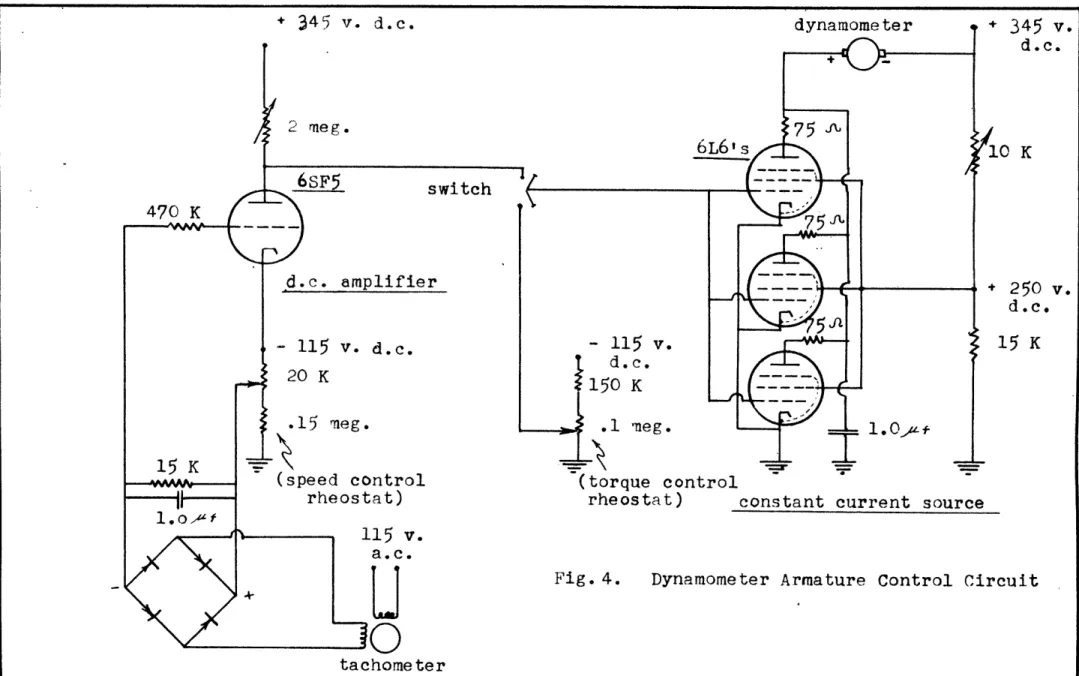
2b. Generator Current Controlling Circuit
The field current or the armature current, or both, may be varied for controlling the air-gap torque. It was decided to employ a shunt generator so that control of the field and armature currents could be made independently. The field current under steady state
con-ditions depends upon the applied voltage and the resistance of the field winding. The armature current, however, depends upon the tera-inal voltage of the generator and the characteristics of the armature circuit and connected load. The field current was to be maintained constant by a constant applied direct voltage, and control of the air-gap torque was to be accomplished by armature-current control. Constant torque could then be obtained, by maintaining constant
arma-ture current.
Employment of a d-c shunt-generator for the dynamometer with armature-current control necessitated that the control circuit have certain requirements, a few of which are the following:
1. The maximum direct current required would be less than 10 amperes.
2. The armature current control circuit must be capable of per-mitting either constant torque or constant speed loading of the tested motor. A selection of constant torque or constant
speed should be made manually by a selector switch.
3. Constant armature current must be maintained even though
the terminal voltage of the generator increases with increased speed.
4. A speed reference voltage must be capable of varying the generator armature current to provide constant speed control. 5. Variations in magnitude of torque and speed during test runs
should be made by control knobs.
A control circuit was sought which would have inherent-constant-current characteristics regardless of the variations of generator terminal voltage with variations in generator speed, yet permit manual changes in the current. This selection would eliminate the need for current-reference and associated feed-back circuits, and re-quire that only speed reference and associated feedback circuits be needed to control the generator armature current.
With the low current demand required by the dynamometer, vacuum tubes were the desirable choice for the current supply. The inherent-constant-current characteristics of pentode tubes permit ease of main-taining constant current, yet permit control of current by a reference voltage applied to control grids.
2c. Speed-Control Voltage
The speed feedback voltage could be obtained from the gen-erator terminals or from a tachometer attached to the gengen-erator shaft. It was decided to employ a tachometer which could be mounted as an integral part of the cradled generator so that the driving torque of the tachometer could be measured directly by the torque-measuring device.
The speed feedback voltage from the tachameter would be com-pared with an arbitrary speed reference voltage, the difference of which would provide the error signal with which to control the
gen-erator armature current when the gengen-erator is operating as a speed regulator.
With the proposed procedure as presented in Chapter 3, the author began construction of a cradled-generator dynamometer and the control circuit. During construction of the dynamometer simplicity in design of the generator cradle and controlling circuit was kept in mind, as accurate torque measurements and load control could always be obtained through ease of maintenance and ease of operation. For this reason, a controlling circuit wgs desired that would have inherent constant current characteristics, so as to eliminate the current control feed-back circuits.
18 L*l --~ l~-L
CHAfPTER
RESULTS
Small-cradled-generator dynamometers of the size to measure the speed-torque characteristics of miniature electric motors can be con-structed to give consistent accurate results. Such small dynamometers, however, must be constructed and handled as precision instruments, and not abused as the large-hp dynamometers commonly found in most electric motor laboratories.
1. Construction of Dynamometer
A cradled-generator dynamometer employing feedback speed control and constant-torque loading of a tested motor was constructed and tested. The dynamometer assembly consisted of a cradled d-c shunt generator, a drag-cup-type tachometer, and a spring-balance torque-measuring de-vice. Pictures of the dynamometer assembly with the tested motor and shaft coupling removed may be found in figs. 1 & 2 on pages 24 &25 . The dynamometer and all control equipment was designed to operate from the standard power panels found in the M.I.T. measurements and machinery laboratories. Where possible, the 345-volt, d-c regulated power supply was used to reduce the errors in measurement that would arise from
normal voltage fluctuations.
Dynamometer speed was determined by a Strobotac, whereas speed-control voltage was determined by a tachometer.
la. Cradled Generator
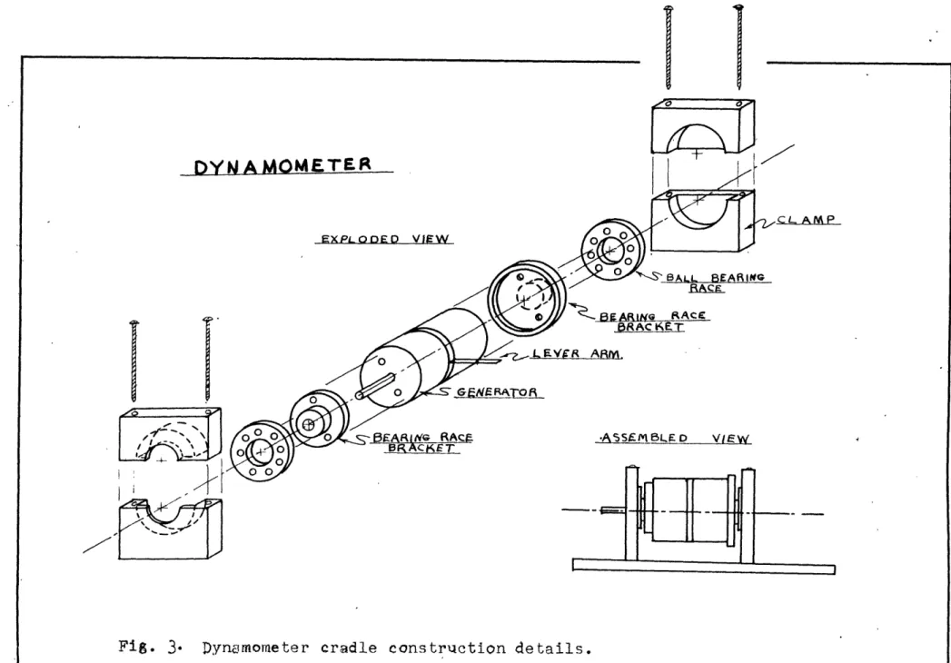
The construction of the cradled-generator dynamometer mounting is shown in fig* 3, page 26. The d-c generator was an *Electric Motors
Corp." motor rated at U15 volts, 0o. amperes, 7000 rpm, and continuous duty.
Ball-bearing races of 2 inches outside diameter and 1 inch inside diameter, clamped by two end blocks to the base plate, were employed in mounting the generator. The large size bearings were employed so that the generator shaft and shaft extension could have friction-free rota-tion through the bearing-race opening. Light-sewing-machine oil was used as lubricant for the ballbearings so that any viscous force due to the oil could be kept at a minimum.
The torque produced by the armature and field lead-in wires was reduced to 0.035 in.-oz. by the use of 10-inch lengths of multiple-strand wire. The wires were looped around the generator frame to reduce the space requirements.
The lever arm which transferred the generator-frame torque to the spring balance was constructed of iron strap and had an effective
length of 2 inches. Acting on this lever arm were two limit stops which prevented large angular deflections on the generator frame. Any sudden or large deflection of the generator frame caused undue strain on the generator cradle, and caused misalignment of the lead-in wires producing a source of varying stray torques.
The generator field current was maintained constant at 0.4 amperes throughout the testing by the laboratory l15-volt, d-c power supply.
lb. Speed-Control Tachometer
The speed of the dynamometer was determined for feedback pur-poses by an "Elnico Midget Rotation Indicator" rated at 110 volts, 60 cycle, 1 phase. The tachometer- and rectifier-output voltage may be
seen in fig. 8, page 31 An RC filter was used across the rectifier
output terminals during the test runs. The tachometer and generator were coupled together through a train of three gears at a ratio of 1:2. The tachometer-feedback-voltage constant was not uniform through-out the entire speed range of 7000 rpm. The variations in the constant may be approximated as follows:
0 - 2000 rpm K=0.0002 volts rpm 2000 - 3000 rpm K=0.0006 volts/rpm 3000 - 7000 rpm K =0.00093 volts/rpm
The external mounting of the tachometer created a torque loss be-tween the driving motor and the spring balance. The minimum torque loss was found to vary from 0.20 in.-oz, at 500 rpm to 0.32 in.oz, at 7000
rpm. This torque increased with accumulation of dirt on gears. Ic. Control of Generator Armature Current
The current-control device consisted of three 6L6 vacuum
tubes circuits in parallel as the current source, and a 6SF5 vacuum tube circuit as the direct-voltage amplifier. See fig. 4, page 27 for the circuit diagram.
For the purpose of maintaining constant torque loading, the 6L6 vacuum tubes were found to be adequate for the magnitude of generator current needed. Approximately constant current was maintained even though the open-circuit voltage of the generator varied from 0 to 125 volts, at speeds f rom 0 to 7000 rpm with a field current of 04 amperes. See fig. ., page 28 for the constant current curves.
The regulated 345 volt, d-c power source was used for three 6L6 and one 6SF5 vacuum tubes. Grid control of the 6L6 tubes provided the means of accurately controlling the magnitude of the generator arma-ture current. For constant torque loading of the tested motor, the control grid voltage was obtained from a potentiometer. The
was connected from common ground through a resistor to minus 115 volt, d-c. For constant speed loading of the tested motor, the control grid voltage was obtained from the 6SF5 tube circuit. The 6SF5 con-trol grid voltage was produced by the difference of the tachometer feedback voltage and the reference speed voltage. The reference speed voltage was obtained from a potentiometer. This potentiometer was connected from minus 115 volt, d-c through a resistor to common ground.
2. Experimental Results
The vacuum-tube generator for controlling armature current was found adequate for the small size of motors to be tested. The control circuit was found inadequate for constant-speed control because of the non-linearity of the-acuum tubes and tachometer feedback voltage throughout the speed ranges desired. Constant-torque control was made possible with a minimum of controls by the inherent-constant-current characteristics of the 6L6 vacuum tubes.
2a. Constant Torque
Constant torque was intended to be maintained by constant arma-ture current. The armature current supplied by the 6L6 vacuum tubes was not constant throughout the speed range of 0 to 7,000 rpm. Fig. 5,
P.28 indicates an increase of current with an increase in dynamometer speed. This resulted in an increase in torque with an increase in speed as shown in fig. 6, p,29 * With a generator torque constant of 2.'37
in.-oz. per ampere, an increase in armature current of 0.2 amperes re-sulted in an increase of torque of 0.47 in.-oz. Besides the increase in torque due to armature current, there was an increase of 0.4 in.-oz. due to the generator rotor friction and windage. The maximum slope of --r -i~--- If-- .
i:F
I
the torque curves, 0.15 in.-oze per thousand rpm, was considered low enough for the purpose of controlling the load on a tested motor.
2b. Constant Speed
The constant speed runs were accomplished by the dynamometer acting as a speed regulator for the tested motor. The runs were made with the speed setting knob set for speeds of 2,000, 3,500, 5,000
and 6,000 rpm at a torque near 5.0 in.-oz. The nonlinearity of the
circuit components and lack of compensation for it is evident from the speed curves. The leveling off of the curves at 1.0 in.-oz, is due to the friction loading of the dynamometer.
2c. Driving Motor Torque.
The indicated torque as obtained from the dynamometer spring scale and mhich has been plotted on the various graphs is not the torque of the driving or tested motor. The correct torque would be the in-dicated torque plus the torque losses. The friction and windage loss torque of the dynamometer hich was not transferred to the generator frame was found to be negligible. The generator cradle torque was found to be 0.035 in.-oz. The tachometer and gear train torque was found to vary from 0.2 in.-oz. at 500 rpm to 0.33 in.-oz. at 7,000 rpm. The driving or tested motor torque would then be the indicated torque plus 0.035, plus the tachometer and gear train torque corresponding to
the designated speed. The gear train torque was found to increase con-siderably with accumulation of dirt on the gear teeth. This increase in stray torque reduces the accuracy in obtaining the tested motor torque.
DYN
A_
MMETE~t
EXPLOnDO VIEW G FR~of -BEARING f*ACf ~13RCET &~SBLLa BA RI IVG F3 FAsume RACCE BRAC KET -A'5SF-ftLUo VIE!WFi8
3'Dynmomtercradle
constriaction details.+ 3 4 5 v. d.c. 2 meg. switch 470 K d.c. amplifier - 115 v. 20 K .15 meg. d. c. (speed control rheostat) 115 v
a.c.
DO
(torque controlrheostat) constant current source
Fig. 4. Dynamometer Armature Control Circuit
tachometer 345 v. d.c. 250 v. d.c. 15 K 15 K -0 .
i i t 14z+-~- I - 1 '-L.. - -4 " hJ -7 45 ~---.r. F34 oil ' i Lr 7 17-T.,~ t~ I-! -J-,
YN40AxE At1AAURi I1REI'TJ vs DYNAMQ~ETrER SPIRED -iQR
t : s: 1 .a~N: A~a i t
A rm'at ure (*urrent bo t Ti'f- k~
:Set at zero ped, Dyha r-), C,tr ia ratureciurte'
with thq corresporfling :-ar~mt -ci r e n t
-77I
i-J
1- I ;i-_.-1 x~L~e--- 1..I
7 T P
I
T 4 1 I~~~~~~ ~ ~>
t
1
~ ~~-1J
Fs~t ar-. i- ! 'I /I tC -Fr1p~,I.
_ _ _ _ __'. :.tI
1j
1tA
71 -7 - t --. j 1 +-44- 1 t 4 f'.; t", L Tc
';' ' i i'::Zb. t -- _I
j
1.".-" r F :,Armature current maintain1- costant
at various invels by means of eon-s"nt'
1~ 1.
Ii
i .1 I. *1 4 .. 02. amp, ' '0.0 amp. . - r a , . a p . o30 mp. c,. 20-- am' i-.. .i.. . O .2.
3
Dynamometer Speed 4 (thousnd rpm) 12 10 I':, .7 TMI~~A~t~h1JX, s. Y~NO~TF METER SPEPO'
REAU4 1) I TtN -YN -
Ii
p!~f;: Ij ' ^j' il^~ "I
. 0 Q 4C!I -aI Fig. 6. ''~' . ~: r -i-.-- , : : i i .-: : -i : !~_ m~rryn~as*, ~ w~j 9 \q *.nuc~ iI ft
I*I-ILI-~lnC~ . .1 :- -~ : -i ~- i. : I: a.. i ,._.. i --- -~-ourypenlt source. o.40 i M ,
C
lak ' : 9
'590
L~T7T7V'77~7 S(judx pun&T4)I p*e~ adoi
'''4,
U;ilW pe,*; 'Q j uo6 paaO V -G~~v 2utvf4 xa~javQWuv ~I~dS~II~I4V~TA0 r I Tdt2t-i
41 *n ~I~TE70,
WciJSud~~o
OT'.TV
0
-t 1t-t~4
0, *1 0:1
I,4-09
-i--I i i( _ ... <! : ].+ i'O'
77,
~T ~ t ~i t ., f71iHrI7 , 7
,
7
F-.'
I
. , -1. "-4 -1, i - I ,,- --- -T' ,;i ---- 4 I,~~~ i - ! I-J ' J-L
7! 7' -:- I -!47,'.-t
ITAi'iii%
~1 v I --7 -1 -17---!
'..
V'3I1..
3-
,
.. ..
.L
:::
L
...
...
_
.. . ...
t.
. . ... .i.
...
...
1-4~
+.,
4f-
m _ ,
. . + . - l! ?x i:
:
.. .... ,,. . . ...
-4,
.. tL- _ L ---._---- ' ._ .. .I-; .. ..2 .:A ' . .. i .. i..._ ... ... .j~ ,- iL; l
"-a"-o !p
...
f IA.
i~~l
i
im
(
..y
.: .m tt:Tr
. ;:' Ll . .. . . 1+'' ,' '; i -,- ' L -'. :Z i ;: ii -1-
,+ .. .. ; ,(",+ i-I+: + . ... --?, r
-J~y~apme teS pb d h and oi
-8 O J +~IT . i'l met e .;m ' , .. - ou a-:II t,-.+- . ; + .p ".L . : I : I - . i -,.1'... _i:~
8 " : . ... i- ' . . . . I- ; . ;- - i, +
' - _< " < , ' - .. .. .. L .. . . ' ++ ", . . . j ... .. ++ . .. . ._ .'. . _ .' +;.. .,++ >+u .+ . . . . .. .. ... . . . . .. .. . . .. . , -. J - .++ .. ..
CHAPTER
-DISCUSSION OF RESULTS
Although the dynamometer as constructed did not function as per-fectly as expected, it was felt that further study in electronically controlled dynamometers would produce more favorable results. Time did not permit construction of a dynamometer that would function with the desired accuracy, but did permit the discovery of various factors which,
if corrected, could make possible the construction of a satisfactory dynamometer suitable for laboratory work.
1. Cradled Generator
Two specific features of the generator were desired. It was neces-sary to arploy a generator vhich had the shaft extended on both ends so that a tachometer could be mounted directly with the generator in the mounting. In the choice of such a generator it was also necessary to
select one having low rotation friction. Due to the limited supply of small motors available for experiment, and since a generator meeting both requirements could not be found, it was decided that a generator with low rotation friction was more desirable than a generator with a
shaft extension on both ends.
The proper mounting of the generator by ball bearing races is an important factor in the construction of the dynamometer. The dynamome-ter shaft must rotate free of the cradle bearings, and the generator and bearing race must be aligned so that their spin axes coincide. Al-though the face of the generator employed had a machined surface to which the bearing mount could be attached, it was necessary to use thin
shims to properly align the bearing race. This was done to provide almost torque-free rotation of the generator frame in the bearing.
It had been suggested to the author that ball-bearing-race start-ing frictor could be minimized, if not eliminated, if the outer race of the front and back bearings were driven in opposite directions, the rotation being made possible by an auxiliary drive motor. The rotation of the bearing races assures that rolling friction instead of starting friction will always be predominant. However, it was felt that such an arrangement would be necessary only for highly accurate work. It was also f elt that the normal vibration of the generator in its cradle would produce enough vibration to free the ball bearings and reduce the start-ing torque to a negligible value. This was found to be the case when reasonable care was exercised to maintain the bearings as dust free as possible.
The placement and choice of generator lead-in wires is an
import-ant consideration in small-dynamometer construction. Before the
arma-ture and field lead-in wires were lengthened or coiled about the
generator frame, a restoring torque of 0.20 in.-oz. per degree was
measured at the generator frame. With wires 10-inches long and coiled about the generator frame to occupy a minimum of space, this torque was
reduced to 0.035 in.-oz, per degree. Since it is desirable that torque
measurements be made with the generator frame always in the same position, that is the lever arm perpendicular to the spring balance, this
re-storing torque can be made very small. It is necessary though to take precautions during testing to be certain that the generator frame be lo-cated properly. This was not always the case with large-hp dynamometers where the torque of lead-in wires is negligible.
YC-It was found that by exposing the dynamometer to the air found in the Machinery Laboratory, enough dirt could collect in and around the bearings to cause a large increase in the torque of the cradle. Thus,
cleanliness of the dynamometer and mounting is essential for accurate torque measurements with small motor dynamometers unless other
pre-cautions in construction could eliminate this.
2. Speed Control Tachometer
Since the circuit employed throughout used direct voltage, it was desirable to employ a d-c tachometer. Due to the scarcity and pro-hibitively high cost of a good d-c tachometer, it was necessary to
employ an a-c tachometer with a full-wave selenium rectifier. The drag-cup tachometer offered the advantage of small rotational friction. This advantage was overshadowed by the necessity of using a gear train to drive the tachometer. Any torque exerted between the generator frame and the driving motor shaft, such as that caused by gear trains, con-stitutes a torque loss resulting in inaccurate torque measurements.
3. Generator Current Controlling Circuit
The non-linearity of the electronic control circuit proved to be the limiting factor when determining its usefulness for controlling the
dynamometer armature current. This non-linearity caused by the 6L6 vacuum tubesmvs anticipated, but no steps were taken to compensate for
it. From the tube characteristics it can be seen that linear control over a wide range of current is impossible, especially near zero current. From the 6L6 tube characteristics and in the proper opersting region, the increment in plate current per' incremert in grid voltage constants may be approximated as follows:
ec = 0 to -20 volts k = .57 amp/volt
ec = -20 to -27 volts k = .35 amp/volt
ec = -27 to -40 volts k- .16 amp/volt
This non-linearity has very little effect on constant torque loading. Once the control grid voltage is set to obtain the desired dynamometer torque the control knob remains fixed* Calibration of the control knob dial in amperes or torque eliminates this non-linearity disadvantage.
With the dynamometer acting as a speed regulator the non-linearity affected greatly the operating characteristics. At very low torques, a large increment in control grid voltage, with a correspondingly larger increment in tachometer output, is necessary to produce an in-crement in current, than the inin-crement needed at higher torques. Poor
speed regulation would then be expected at low torques, because of the characteristics of the 6L6 vacuum tube.
4.
Driving MotorThe drive motor for the dynamometer, which would ordinarily be the tested motor, was a d-c shunt motor manufactured by "Delco Motors", and rated at 27 v., 1.5 ampere, 4 in.-oZ, 5400 rpm. To accurately deter-mine the discrepancies between the driving motor torque and the dyna-mometer indicated torque, the drive motor should also be mounted in a cradle and its torque measured simultaneously. Time did not permit construction of two cradles, so the input current and voltage of the drive motor was measured with all test runs, from which calculated values of torque could be made. Although the resistance of the driving motor armature varied considerably due to copper losses, the calculated values of torque gave consistent values when averages were taken. It was from g _ _____~____=
these calculated values that the tachometer and gear train torques were obtained. The metering diagram used for all tests is shown in
fig. 9, p. 32 *
Under normal operation it is usually assumed that motor torque does not vary with angular deflection. Fluctuation in air-gap torque is noticeable at low speeds due to slots and pole effects. To be able to measure these fluctuations in torque, such as at zero speed, it
would be necessary that the generator used as a dynanometer have torque smaller
fluctuations of considerablymagnitude than that of the motor. Since the generator used as the dynamometer was somewhat the same size as the drive motor, the torque fluctuations were not considerably smallero These fluctuations were noticeable at speeds below 600 rpm, but they were not measurable.
---CHAPTER 6
RECOMMEBDATIONS
The study of electronically controlled dynamometers should be continued. After the tests made on the dynamometer were completed it was found that various disadvantages might be eliminated and the accuracy in torque measurement improved if other components were used in its constraction. To improve upon the design the following recom-mendations were made.
The disadvantage of vacuum tube circuit non-linegrity could be minimized if push-pull circuits were used. The cradled generator would need opposing field windings thro ugh which torque control could be made. The armature current could be maintained constant, as
de-sired, by a vacuum tube or mechanically regulated power supply.
A d-c (pm) tachometer would provide a more accurate feedback
volt-age than an a-c tachometer with a rectifier. However, with the d-c tachometer it is important that the brushes do not cause erratic out-put voltage. One of the important means of preventing this erratic voltage is to use hinge-type brush holders. If a choice of d-c
tach-ometers is being made, it is important to select the one with the
greatest number of commutators, all other things being equal. A
smooth-er output voltage results from the greatsmooth-er numbsmooth-er of commutator bars.
Tachometer loading and tachometer stray torque losses can be eliminated if the tachometer is not used for the feedback voltage.
Mounting of the t achometer as an integral part of the dynamometer or mounting it externally from the dynamometer may be eliminated if the
dynamometer generator terminal voltage is used for the feedback
voltage. The use of the generator terminal voltage requires that the terminal voltage be altered to compensate for the rotor IR voltage drop. Feedback voltage from the generator also requires that the generator field current be maintained constant at all times.
With the various torque losses associated with a cradled gener-ator and auxiliary equipment, and the corresponding inaccuracy in
determining the tested motor torque, it would seem worthwhile to invest-igate the design of a torque meter. The meter to be coupled between the tested motor and the generator is to reduce stray torque losses. The dynamometer could then be changed to a non-cradled generator. It is still essential,for stable operation, that accurate loading be maintained. With an electronically controlled generator and a direct coupled torque meter, accurate loading and torque measuring could be done.
S- --- C- --- -- _
APPENDIX
Constant Torque Loading by an Induction Motor
Prior to the design and construction of a sub-fractional hp electric motor dynamometer, it was attempted to determine if induction motors
could be employed as a constant-torque load for fractional hp electric motors. It was intended to apply induction motors that possessed
con-stant torque characteristics in the speed region of greater than 100 percent slip. It was realized that the rotor currents and copper losses would be considerably larger than the rated current or rated copper loss,
but it was felt that with reduced voltage these could be reduced to reasonable values.
The advantage of an induction motor over do motors would be the elimination of brush friction. The advantage of inherent constant torque characteristics would be the elimination of auxiliary control equipment to maintain constant torque.
Calculations were made with a 1-hp, 2-$ squirrel-cage induction motor. Several values of rotor resistance were used to show
correspond-ing changes in motor torque. See fig. 1, page 42 for this variation in motor torque. The induction motor constants were obtained from tests
conducted in the laboratory, and the Thevenin' s equivalent circuit was used for the calculations.
The variations of torque and copper losses with rotor speeds from
0 to 200 percent slip have been plotted at various values of applied
voltage. These curves may be seen in figs. 2 & 3, pages 43 and 44 . At rated operating speed and load and normal rotor resistance of 3.55 ohms per phase, the combined rotor and stator copper losses
(neglecting iron losses) were found to be less than 0.035 KW. To per-mit this same copper loss, for which the motor was designed, at all speed above 100 percent slip, the maximum torque that could be obtained for loading would be less than 0.1 ft.-lb. This is lower than wruld be practical for t est purposes.
With the rotor resistance increased so that maximum torque occurred at 100 percent slip, the copper losses were reduced. The reduction in losses was not enough to permit using the induction motor as a constant torque load, even at reduced voltage.
To satisfactorily apply the induction motor as a constant torque load it would be necessary to use forced cooling to dissipate the heate Forced cooling for motors which have a large heat dissipation is
usually done with an externally driven forced air fan built into the frame of the motor.
Itf
-e,
Wesb.Liglous 1H. P.
qirrel ae inducln
Motor•-i-;Westinghouse, IH P., . 1.il., - . ' '
2Z0
vlt 60 cycle
r is rato resistence/phase - . -i J 7-- -.I K
11-
ii -1-. _I _: _ii-i. 1 L 4 4I i-;1- I- 7---I-.. ... - .. . 2--- i6-- i4 12 10o
~1~1 .I - -I ... - -- . ______~_ _f r
jt i i._.__.,_
i--,i
i-
9T Vt~ ZT OT T ~Cr ri/ L C --- C \%. 4 xii 7 -C- I --ptiI---
-I
';
I
LIEI A t -i~ --- l -- -H -i i- _ :... _..: i 44.. -z- , --- -- I- 44-~- --I- -1 -I I-.>17
4
rL1±111.~
e~! i~-o!pt
i JS, -L, -j~ Ci I r- i CL~-Y -- r-C, :, vI ---tt I-~ ~ -l -s-roi y-. i---- --I i -_-.f~-~c~1 -4 :is
eue~4~~of
i I ii :. l_._.i i .. I R(~/~B~PI~S' -iI ?-
ii.;
t" I I j t .1~' ''' ----, ---t t ( rd * J paqul) (lhdB at VLW7 --
7I
17
1
77i~
H rA~~ --~em
L 6t t 1 I .. V 3 i- 4P is measured Torque =(FI+ F )r
Torque=PX
-W,X,#Y are constents
Fig.4 a. Prony Arake
Torque=PX t- Friction & Windage.
W ere t
."-&--Flux density
o=Angular velocity Fig. 4 c. Eddy Current Brake
-- _ x Power supply
P (Es)
Torque =PX= KEB (
Fig. 4 e. Magnetic Clutch
r
I
Thread makes several turns around pulley.
P1 is measured Torque =(P - P )r
For Torque =Pr, P2= 0
Fig. 4 b. Thread & Fulley Erake Power sin or source.
Torque=PX - Friction & Windage. PX is a functirn of the gen-erator - load characteristics.
Fig. 4d. Generator Dynamometez
T T T Accelera'tn run Deel era'tn run TIE T iE
'orque (I)= Joace. torque (2) = JcAdeco
'orque (net)= Torque (1) plus Torque (2). da= dN/dt
Fig. 4 f. Indirect Measurement
Fig. 4. LOADING DEVICES. Methods of ]oadin
8 to provide torque measurement of shaft torque.
TORQUE Running winding tarting winding TORQUE
Fig. 5a. Induction Motor
TORQUE
Fi. 5c. Synchronous Motors
Differertiel compd.
ShVnt
TOPQUE
Fig. 5 b. D.C. Motor s
TORQUE
Fig. 5 d. Hysteresis Motors Fig.5. SPEED-TORQE CHARACTEATSTICS. Curves represent the typical speed-torque characteristics of small electric motors.
CONSTAN TOSQUE LOAD
Fig. 6.MMTOR-LOAD STABILITY. Criterion for stability is
dT /dN>dT./dK. Stable and unstable operating regions are showri for loads having variable cons'tarnt torque and variable constant speed
characteristics. Conditions of dTL/d-t4 dTUd is considered unstable. CONSTANT SPE:D LOAD
Sample Data Sheet
Constant Torque Runs Dynamometer If is 0.4 amperes
(Dynamometer)
Ia N F
amps rlpa oz. *o
.05
.05
.05
.05
.05.15
.15
.15
.15
.15
.15
*25
.25 .251.255
.30 .31 .315 .30 .315.4o
.41
.41
.42
03750
4710
5900
68501500
2530 3670 4260 48205750
9801850
2520 2770 9204700
6400 2800 6800655
3100
39006940
Drive Motor Ia 'a amps d.c.0.5
1.61.65
1.65
1.65
2.7 2.7 2.72 2.75 2.75 2.75 3.73.75
3.76 3.8 0.614
.642.675
.70.955
.995 1.0341.05
1.07 1.101,41
1.58
1.42
1.4
Tachometer va aeC 0 17.9 22.3 27.131.5
9.5
14.1
18.7 21.6 23.6 28.0 03.6
4.6
5.8
6.8 1.22.4
3.4
4.0
4.5
5.4
8.*
12.5 16.0 17.54.75
5.02
5.2
4.9
5.2
5.9
6.2
6.2
6.35 --BIBLIOGRAPHY
1. Arslan, Hilmi M., "Design of a Variable Speed Drive",
M.I.T. E.E. Thesis, 1948.
2. Blackburn, Components Handbook, M.I.T. Radiation Laboratory Series, VolT. 177 McG.ra-Hill Book Company, Inc.
New York, 1947.
3. Bross, R.B., "Measurement of Speed vs. Torque in Small Motors", Electrical Manufacture, Vol. 41, Jan., 1948, p. 113-5.
4. Dougherty, E.K., "Design, Construction, and Test of a
Fractional H.P. Cradle Dynamometer", M.I.T. E.E. Thesis, 1935. 5. Kloeffler, Brenneman, & Xerchner, Direct Current Machines,
The Macmillan Company, New York, 1934,1 p. 163.
6. Koopman, R.J.., "Characteristics of a 2
X
Servo Motor", A.I.E.E., Sept., 1949, Vol. 68.7. Marcy, H.To, "Analysis of the Dynamic Operation of Small Electric Motors", M.I.T. E.E. Thesis, 1941.
8. Nelson, G., "Magnetic Fluid Clutch in Servo Applications", Electronics, Nov., 1949, Vol. 22.
9. Puchstein & Kimberly, Universal Electric Motors, Their General Properties, Performances, and Design., The Ohio StaEe University Engineering Experimental Station Bulletin No. 53, Feb., 1930, 10. Puchstein & Campbell, Voltage Relation and Losses in Small
Universal Motors., The Ohio State Univ. Eng. Exp. Station Bulletin No. 58, Jan., 1931.
U. Ricker & Tucker, Electrical Engineering Laboratory Experients McGraw-Hill Book Company, Inc., New York, 1941.
12. Timson, E., "Development of a Speed Torque Test Method for Fractional H.P. Motors", M.I.T. E.E. Thesis, 1940.
13. Wolf, S.S., "An Automatic Test Board for Small Motors",
Electrical Engineering, Vol. 68, Aug., 1949, p. 655.
14. Wommack, K.L., "Magnetic Coupled Torque Meter for Measurements of Torque", Elec. Mfg*, Vol. 39, May, 1947.