1
Delivery of Macromolecule Therapeutics via
Jetting in the Gastrointestinal Tract
by
Graham Arrick
Submitted to the
Department of Mechanical Engineering
in Partial Fulfillment of the Requirements for the Degree of
Master of Science in Mechanical Engineering
at the
Massachusetts Institute of Technology
May 2020
© 2020 Graham Arrick. All rights reserved.
The author hereby grants to MIT permission to reproduce and to distribute publicly paper and electronic copies of this thesis document in whole or in part in any medium now known or hereafter created.
Signature of Author:
Department of Mechanical Engineering May 15th, 2020
Certified by:
Carlo Giovanni Traverso Assistant Professor of Mechanical Engineering Thesis Supervisor
Accepted by:
Nicolas Hadjiconstantinou Professor of Mechanical Engineering Chairman, Department Committee on Graduate Theses
2
Delivery of Macromolecule
Therapeutics via
Jetting in the Gastrointestinal Tract
by
Graham Arrick
Submitted to the Department of Mechanical Engineering
on May 15
th, 2019, in Partial Fulfillment of the
Requirements for the Degree of
Master of Science in Mechanical Engineering
Abstract
Biologics are a class of therapeutic substances composed of large and complex “macromolecules.” Examples include vaccines, insulin, monoclonal antibodies, and allergens. However, a practical limitation of these molecules is that they are easily degraded by digestive processes and, as a result, are not generally considered effective for oral dosing. Therefore, these life-saving drugs are typically delivered via intravenous, intramuscular or subcutaneous injection. Oral administration, however, yields some of the highest patient adoption and adherence rates, and is often critical in determining a drug’s efficacy. Herein lies the goal of this research: to make it possible to successfully deliver a broad set of biologics by mouth. To that end, needleless delivery, or jetting, has been identified as a promising approach. This work describes mechanistic modeling of jets, an empirical evaluation of jet interaction with gastrointestinal tissues, a millimeter-scale jetting device capable of autonomous drug delivery, and in-vivo studies in which the tested devices elicit substantial drops in blood glucose levels via the delivery of insulin across the gastric mucosa.
Thesis Supervisor: Carlo Giovanni Traverso
3
Acknowledgements
First and foremost, the author would like to thank Miss Yi “Louise” Lu of the University of Toronto for her consistent dedication to our work as well as her overwhelming positivity and general kindness. The execution of much of our experiments, as well as the formulation of this document would not have been possible without her.
Secondly, the author would like to thank Declan Gwynne and Jake Wainer for being excellent engineers, co-workers and, above all, friends. Their ongoing support with mechanical design analysis and testing, as well as their creativity has been a crucial part of this effort.
The author would also like to thank Torben Sebastian Last of the Kungliga Tekniska Högskolan, who is an extremely disciplined scientist and a great friend. His ideas, consultation, analysis and moral support (as well as his home cooking), were all critical in the success of this thesis.
Next, the author would like to extend a word of appreciation to Alex Abramson, Jason Li, Siheng “Sean” You, and Param Karandikar—researchers in our group whose wisdom was enlightening in the face of uncertainty.
The author would also like to extend gratitude to Novo Nordisk, not only for providing funding for this project, but for providing access to brilliant scientists and engineers. The author is particularly grateful for the ideas contributed by Drago Sticker, Aghiad Ghazal, Morten Frederiksen and Brian Jensen.
A great deal of thanks is owed to our wonderful veterinary technicians (present and former), including Joy Collins, Siddartha Tamang, Keiko Ishida and Cody Cleveland, whose expertise and flexibility made the documented in vivo work possible. The author also owes much thanks to the Autotiv machine shop for its ability to quickly produce high quality millimeter-scale parts.
Finally, the author would like to thank Professor Carlo Giovanni “Gio” Traverso of the Massachusetts Institute of Technology, for his constant optimism and his uncanny ability to think outside of the box. Gio’s unwavering support of the author’s efforts, as well as his keen guidance on project management, were essential in realizing ingestible jetting. Gio’s dedication to innovation is only rivaled by his dedication to creating a caring and inclusive community.
4
Contents
Table of Figures ... 7
1 Introduction ... 8
1.1 The Problem: Non-adherence to Biologic Dosing Regimens ... 9
1.2 History of Jetting ... 10
1.3 Prior Art in the Oral Delivery of Biologics ... 12
1.3.1 MucoJet ... 12
1.3.2 Solid Micro- and Mili-needles ... 13
1.3.3 Liquid Injection with Hypodermic Needle ... 13
1.3.4 Absorption Enhancers ... 13
1.3.5 Enzyme Inhibitors ... 14
1.3.6 Nanotechnology ... 14
1.3.7 Iontophoresis ... 15
1.4 Biologics... 15
1.4.1 Molecules for Glycemic Control ... 15
1.4.2 Vaccines ... 16
1.4.3 Monoclonal Antibodies ... 16
1.4.4 Therapeutic Protease Inhibitors ... 16
1.4.5 Hormones ... 17 1.4.6 Allergens ... 17 1.5 Gastrointestinal Anatomy ... 17 1.5.1 Buccal Space ... 18 1.5.2 Esophagus ... 18 1.5.3 Stomach... 18 1.5.4 Small Intestine ... 19 1.5.5 Large Intestine ... 19 1.5.6 Rectum ... 19 2 Jetting Mechanics ... 20 2.1 Modeling ... 20 2.1.1 Spring Model ... 21 2.1.2 Energy ... 21 2.1.3 Bernoulli’s Equation ... 22
5
2.1.4 Dynamics ... 23
2.1.5 Losses ... 26
2.1.6 Sample Model Outputs ... 27
2.2 Experimental Methods ... 28 2.2.1 Testing apparatus ... 28 2.2.2 Data collection ... 31 2.3 Data Processing ... 31 2.4 Experimental Results... 32 3 Tissue Characterization ... 34
3.1 Ex Vivo Experimental Methods ... 34
3.1.1 Testing Apparatus ... 35 3.1.2 X-ray Microtomography ... 35 3.1.3 Histology ... 35 3.2 Ex vivo Results... 36 4 Device Development ... 40 4.1 Engineering Requirements ... 40 4.1.1 Avoidance of Obstruction ... 40 4.1.2 Reduction of Trauma ... 41
4.1.3 Minimization of Delivery Failures... 41
4.1.4 Use of Non-toxic Materials ... 41
4.1.5 Shelf-life ... 42
4.2 System and Sub-system Concepts ... 42
4.2.1 Target Organ: Stomach ... 42
4.2.2 Tissue Localization: Self-orientation ... 43
4.2.3 Power: Compressed Gas ... 44
4.2.4 Triggering: Sugar-Plug ... 45
4.3 Integrated Device Design ... 45
4.4 Device Experiments ... 47
4.4.1 Triggering Tests ... 47
4.4.2 High-speed Imaging ... 47
4.4.3 Device Tissue Performance Testing ... 48
4.5 Device Testing Results ... 48
5 In Vivo Work ... 52
6 5.1.1 Insulin Formulation ... 53 5.1.2 Deployment ... 53 5.1.3 Blood Collection ... 54 5.2 Bioanalysis ... 54 5.3 Results ... 55 6 Conclusion ... 56 6.1 Discussion ... 56 6.2 Future Work ... 57 Bibliography ... 59 Appendices ... 63
I. Additional N-SOMA Device Design Details ... 63
II. N-SOMA Device Assembly Procedure... 67
III. N-SOMA Device Leakage Testing ... 67
7
Table of Figures
Figure 2.1: Diagram of a spring-powered jetting system. ... 21
Figure 2.2: Theoretical jetting performance over range of nozzle orifice sizes. ... 28
Figure 2.3: Testing apparatus used for validating jetting performance ... 29
Figure 2.4: Diagram showing section views of different versions of the PortoJet ... 30
Figure 2.5: Triggering mechanism for PortoJet ... 30
Figure 2.6: Experimental jetting performance over range of nozzle orifice sizes. ... 32
Figure 3.1: Experimental work-flow for ex vivo tissue testing and imaging ... 35
Figure 3.2: Micro-CT images of depots in GI tissue after 200µL jet injections ... 36
Figure 3.3: Histology of stomach tissue ... 37
Figure 3.4: Preliminary summary of peak jetting peak pressure performssue ... 38
Figure 4.1: A self-orienting device ... 43
Figure 4.2: Diagram of the “Sugar-plug” triggering mechanism ... 45
Figure 4.3: Graphics showing the integrated N-SOMA device. ... 46
Figure 4.4: Test setup for high speed imaging of N-SOMA triggering ... 47
Figure 4.5: Images of the membrane after rupture ... 48
Figure 4.6: High-speed imaging of N-SOMA jetting event ... 49
Figure 4.7: Timeline of the N-SOMA expulsion event ... 50
Figure 4.8: Frozen sections of stomach tissue after injection with N-SOMA ... 50
Figure 5.1: Surrogate tethered jetting device used for endoscopic in vivo studies ... 52
Figure 5.2: Deployment of the surrogate tethered jetting device in a pig stomach ... 53
8
1 Introduction
Within the fields of pharmacology and molecular biology there exist two broad classes of molecules: small molecules and macromolecules. Small molecules readily diffuse through cell membranes, and can be absorbed into the bloodstream through the digestive process. Macromolecules weigh more than 900 Daltons, and do not readily undergo trans-cellular diffusion [1][2][3]. Macromolecules are synthesized through biological processes—thus, they are often referred to as “biologics.”
Historically, small molecules have been used in pharmacology more widely than biologics. This is due to their comparatively low cost and their simplicity of administration [4]. As evidence of this: small molecules have accounted for more than 70% new of drugs available on the market since 1996 [5]. That said, sales of biologics have come to play a much more significant role in the market in recent years. According to an annual report on pharmaceuticals, in 2016 “biologics accounted for six of the top-eight drugs, in terms of revenue... [Humira] led the way, with a total of $18.4 billion sales”. Also, according to the same source, “the global biologics market is expected to register a [cumulative growth] of about 10.5% during the 2018-2023 forecast period” [6].
These trends can be attributed to advances in pharmacologic technology, which have enabled the synthesis of more complex molecules [4]. Furthermore, there has been a significant increase in chronic diseases that necessitate biologic treatments. For example, in the United States, the number of patients carrying a diagnosis of Diabetes Mellitus (diabetes) rose from approximately 6% of the population (16.9 million) in the year 2000, to 9% of the population (29.7 million) in 2018 [7]. The discovery of new macromolecule treatments for other diseases such as plaque psoriasis, Crohn’s disease and cancer has contributed to the growth of the biologics market as well.
9
That said, a key limitation of biologics is that they cannot be administered orally, as digestive acids and enzymes cause these molecules to degrade before they are absorbed into the bloodstream [1]. To rephrase: biologics have low bioavailability when swallowed, and as a result, they are widely administered through other methods such as subcutaneous injection, intravenous infusion or wearable pumps. These methods of administration are considered to be more invasive than the oral route, and are widely believed to lead to problems with patient adherence.
1.1 The Problem: Non-adherence to Biologic Dosing Regimens
Adherence is defined by the World Health Organization as “the extent to which a person’s behavior—taking medication, following a diet, [or] executing lifestyle changes—corresponds with agreed recommendations from a health care provider” [8]. Failure to adhere is called “non-adherence.” Non-adherence exists no matter what disease a patient has, no matter what type of treatment is recommended by their healthcare provider, and no matter what level of accessibility the patient has to healthcare resources. Lapses in patient adherence result in a reduced quality of life, increases in morbidity and mortality rates, and wasted health care resources [9]; in the United States, up to 10% of hospitalizations are the result of poor medication adherence [8].
As noted previously, biologics’ low bioavailability necessitates the use of invasive routes of administration. This means that for biologics, drug routine adherence is especially low. Up to 45% of patients diagnosed with Type 2 diabetes do not adhere to their prescribed treatments (the main treatment being self-administration of insulin) [9]. Patients with diabetes who do not receive proper therapeutic treatment can experience prolonged hyperglycemia resulting in dehydration, fatigue, weight loss, nerve damage, further reductions in pancreatic function, kidney failure, and even coma or death.
A study on adherence to subcutaneous injection of insulin revealed that patients attribute their failure to adhere to a number of shortcomings of biologics. Among these are perceived complexity associated with preparing injections, pain or irritation from injections, and fear of needles [10][11]. Additionally, the high price of insulin as well as challenges associated with insurance coverage further reduce adherence [12].
In summary, despite the fact that many life-saving biologic treatments have been developed, the healthcare system still experiences a tremendous burden due to these medications’ amplification of adherence issues. Thus, there are broad-reaching efforts to improve biologics by
10
streamlining their administration. For example, patients are known to prefer auto-injectors over syringes and, as a result, numerous healthcare providers recommend them as a means for administration [13][14]. Moreover, advances in “smart” technology have simplified the use of continuous insulin pumps.
This work seeks to address the problem of patient non-adherence to macromolecule treatments by implementing an ingestible device for the oral delivery of a broad range of biologics. The use of such a device would be identical to that of a typical small-molecule therapeutic tablet. Rather than passive chemical absorption however, the device incorporates an onboard actuation mechanism and means for self-triggering. This thesis identifies needleless injection, or jetting, as a simple and effective means for penetrating the gastrointestinal (GI) mucosa, and delivering liquid depots for systemic uptake.
This work covers the fundamental mechanics of jetting, an empirical evaluation of jetting in multiple types of tissue, design of an autonomous, cm-scale device, and a demonstration of concept feasibility through in vivo testing in a large-animal model. The data presented in this thesis suggests that jetting represents a promising path for the future of oral delivery of macromolecules, and could also be applicable to other GI-based procedures such as endoscopic injections.
1.2 History of Jetting
The earliest known needleless injector was described in Gelante and Béclard’s report of an instrument for performing aquapuncture in an 1866 issue of the Gazette Médical de Paris [15][16]. Note that this was only 13 years after the introduction of the hypodermic needle [17]. Subsequent reports of the aquapuncture device could not be located and the device was likely not developed further.
Decades later, in 1929, a mechanical engineer from New York, named Arnold K. Sutermeister, began developing a needleless injection mechanism. Sutermeister had been inspired by his past observations of inadvertent penetration by pressurized oil into the flesh of engine workmen. Following promising experimental results, Sutermeister shared his work with doctors at the New York Presbiterian Hospital and Columbia University, who later disclosed the concept to the Cambridge Instrument Company [16].
The earliest known patent for a needleless delivery mechanism was granted to Marshall L. Lockhart of Detroit, in 1943 [18]. Lockhart learned of Stutermeister’s device during his time
11
working at the Cambridge Instrument Company, and independently developed a much-improved version [16][18]. Lockhart was later employed by the Gelatin Products Corporation and by Becton, Dickinson & Co. Both companies eventually claimed intellectual property rights over Lockhart’s device [16].
Since Stutermeister and Lockhart’s time, over 2000 patents relating to needleless devices have been granted to various companies and inventors [19]. Table 1.1summarizes the intellectual property space for needleless devices since 1940.
Table 1.1: Intellectual property space for needleless delivery since 1940 [19] Time-period Num. of Needleless patents during time-period Company with most patents granted Company’s share of time-period patents
1940-1960 98 Becton, Dickinson & Co 27%
1960-1980 97 Scherer - Gelatin Products Corp. 12%
1980-2000 574 Bioject Med. Tech. 7%
2000-2020 1361 Antares Pharmaceuticals 8%
Most jetting systems are designed to have a high initial “peak” pressure, which serves to quickly form a hole in the skin. This hole allows for the injection of the remaining volume at a lower “delivery” pressure. Peak and delivery pressures for a sample set of historical jetting devices have been tabulated in Table 1.2, along with their respective nozzle orifice diameter. These orifices’ diameters are generally smaller than the outer diameter of a 30 Gauge hypodermic needle [20].
Table 1.2: Summary of historical needleless devices with estimated peak and delivery pressures [19][21] Year Patent number Inventor Company diameter Orifice
(µm) Peak pressure (Bar) Delivery pressure (Bar) 1943 US2322245 Lockhart - 100 710 -
1956 US2754818 Scherer Gelatin Prod. 50-250 710 140
1995 US5399163 Peterson et al. Bioject 80-130 280-310 80-140 1997 US5599302A Lilley et al. Antares 165 >140 100-140
2011 US20110288521A1 Bingham PharmaJet 180 225 -
12
Despite its regular use, however, this technology has never been applied to achieve submucosal delivery from an autonomous pill. The closest embodiment was reported by Aran et al. [22] but, as will be discussed shortly, this device is neither ingestible, nor does it develop pressures that are sufficient to create submucosal depots in GI tissue.
That is not to say it is difficult to generate such pressures in an ingestible device. In fact, this thesis contends that creating a small-scale, pressurized ingestible device is both simple and safe. As a thought experiment: consider a small disk-spring capable of applying 160 N in compression (such as McMaster-Carr 9712K54 [23]). A stack of these springs coupled to a six-millimeter-diameter piston would embody a single-use hydraulic actuator capable of generating more than 60 Bars of pressure. Proper selection of housing materials would mitigate any concerns related to device failure. Thus, one could infer that it is possible to implement a high-pressure, spring-based jetting device at sub-centimeter scales.
1.3 Prior Art in the Oral Delivery of Biologics
To date, dozens of solutions have been proposed for the oral delivery of biologics. Methods range from direct penetration of the mucosa by solid micro needles to excipient-based modification of local enzymatic activity in the GI tract. Unfortunately, few solutions have produced ‘double-digit’ bioavailability (i.e greater than 10%), which would be an essential step for practical use [11][24]. This section presents a brief review of previous solutions for the delivery of biologics as a means for providing further context for the proposed work in this thesis.
1.3.1 MucoJet
It is important to acknowledge that jetting has been employed in the past for the oral delivery of macromolecules by Aran et al. Their device, which is called “MucoJet”, is held in the mouth against the mucosa, while the hydration of an internal acid-base matrix results in pressurization of the device and subsequent expulsion of the jet [22]. MucoJet, however, is only reported to provide superficial penetration of the mucus layer (not the epithelium). Though this may be sufficient for mucosal immunization purposes, it likely would not be effective for delivery of therapeutically significant doses of biologics such as insulin. MucoJet will be discussed further in subsequent sections.
13 1.3.2 Solid Micro- and Mili-needles
Abramson et. Al demonstrated a device capable of delivering macromolecules with high bioavailability via the oral route. This device employs a spring-actuated millimeter-scale needle (mili-needle) which is passively localized to the stomach mucosa via self-orientation. Delivery of the mili-needle is triggered via dissolution of a structural carbohydrate member. The needle in this device was reported to create a penetration wound (approximately 1mm in diameter) at the site of injection. However, this side-effect was not proven to cause health complications in in vivo swine studies [25].
The luminal unfolding microneedle injector (LUMI) is another example of a device platform that seeks to orally deliver macromolecule drugs by use of dissolvable needles. This system is designed to deploy and expand in the small intestine. It has three biodegradable arms, each bearing a patch of 1-mm-long, dissolvable, drug-loaded microneedles. The device is contained in a capsule comparable in size to a 000 pill. This capsule is sealed by an enteric polymer that dissolves upon entry into the small intestine, allowing for release of the device. The LUMI demonstrated bioavailability larger than 10% over a 4-hour sampling period [26].
Rani Therapeutics, a company focused on devices for oral delivery of therapeutics, has also proposed a system for delivering solid mili-needles in the small intestine [27][28].
1.3.3 Liquid Injection with Hypodermic Needle
Hypodermic injection has been used to deliver biologics such as epinephrine to the GI tract (through use of an endoscope) [29]. Though no reports of an autonomous device designed to inject the mucosa with a hypodermic needle have been located, it would certainly be possible to implement such a device. This device would require a mechanism to deploy the needle, deliver the dose, and retract the needle.
1.3.4 Absorption Enhancers
Absorption enhancers, often referred to as permeation enhancers, are excipients that could allow macromolecules to more readily transverse barriers to systemic uptake such as the mucosal epithelium [30]. A class of an absorption enhancers that has received attention recently is Ionic Liquids. These compounds have been demonstrated to both enhance diffusion through the epithelial barrier, as well as decrease enzymatic activity at the site of deployment. The functional
14
mechanisms for ionic liquids are not well understood, but they show promise for oral delivery of biologics [24].
Yet another recent advance in absorption enhancement of biologics was demonstrated by Buckley et al. in their study of sodium N-[8-(2-hydroxybenzoyl) aminocaprylate] (SNAC) as an excipient for oral Semaglutide. In this study, the authors demonstrated that SNAC increased the solubility of Semaglutide as well as performing other functions to assist with absorbtion. That said, the authors report that the use of SNAC based excipients still only offers single-digit bioavailability [31].
1.3.5 Enzyme Inhibitors
Certain compounds have been proven to limit the impact of digestive enzymes on the degradation of orally administered biologics. Protease inhibitors for example, bind to active sites on protease enzymes, limiting their metabolizing functions. As an excipient, protease inhibitors have been shown to protect macromolecules from degradation [24].
Inhibition of enzyme activity can also be achieved by altering the local pH in the lumen as certain enzymes only function at a specific pH. For example, citric acid, used as an excipient for an oral formulation of recombinant salmon calcitonin (TBRIA), was shown to lower the local pH of the duodenum, thereby inhibiting proteases from degrading the active biologic [24]. Buckley et al. reported that SNAC had the effect of raising local stomach pH, thereby protecting Semaglutide from pepsin as well.
1.3.6 Nanotechnology
Nanotechnology, in the context of drug delivery, usually refers to engineered vehicles that vary in size from 10 nm to 1000 nm [32]. An example of a nano-vehicle is a solid, polymeric or metallic sphere with biologics conjugated to the surface or embedded within its constitutive matrix [32]. Nano-vehicles can also be a hollow sphere, or nano-capsule, with the active agent contained in its center. Though there is much left to be understood, these vehicles have been observed to selectively permeate different cell types depending on factors such as vehicle size and surface chemistry. They are also thought to protect macromolecules by providing a physical barrier against enzymatic interaction. Current challenges in the field of nano-vehicles include toxicity, long-term stability and pH sensitivity [33] [34].
15
Another example of nanotechnology for delivery of biologics is the use of exosomes. Exosomes are a type of naturally synthesized extracellular vesicle (EV). They have diameters ranging from 30 to150 nm and are theorized to be employed in intercellular signaling mechanisms. Recent research efforts have aimed to modify these EVs for containment of proteins, lipids and genetic materials for the purpose of drug delivery. Exosomes show particular promise as they are non-immunogenic by nature [35][36].
1.3.7 Iontophoresis
Iontophoresis is a type of transdermal drug delivery technique which could be employed for oral delivery of biologics. It is used to enhance flow of charged molecules through cellular barriers by providing a potential drop through the subject tissue [37]. Though implementation of an ingestible iontophoresis device would require significant miniaturization of contemporary driving electronic systems, recent advances in power technology could enable their implementation [38]. That said, iontophoresis has been used to enhance local delivery of macromolecules in the oral cavity [39].
1.4 Biologics
There are many different biologics that could be deployed by an ingestible jetting device. As such, ingestible jetting should be considered a platform technology. That said, insulin was selected as a model drug given its clinical ubiquity and the fact that insulin produces an immediate drop in blood glucose (BG) which can be directly observed during experiments without bioanalysis. This section briefly details each type of biologic that was considered for this work, and which could be used in future work.
1.4.1 Molecules for Glycemic Control
Insulin is a peptide hormone secreted by the beta cells of the pancreatic islets. It is involved in multiple anabolic processes such as glucose uptake, and regulating carbohydrates, lipids and proteins. Insulin was discovered by Banting, Best and Macleod at the university of Toronto in 1921, and was first used for treatment of diabetes in 1922 [40]. It is a dipeptide with 51 amino acids and a molecular weight of approximately 5800 Daltons. Insulin helps convert sugars into energy which is eventually stored in muscle, fat cells and the liver. It accomplishes this through glycolysis, glycogenesis and lipogenesis. These functions, among others, lead to a reduction in blood glucose concentration [41].
16
Glucagon-like Peptide-1 (GLP-1) receptor agonists, which mimic GLP-1s, have also proven effective for glycemic control. GLP-1 is a naturally occurring incretin hormone which both stimulates insulin secretion and inhibits glucagon secretion [42]. It has also been shown to play a role in gastrointestinal activity such as motility and mucus secretion, and appears to have a neurological impact, causing reductions in appetite [43]. As a result of the above functions GLP-1 receptor agonists have been marketed widely for the treatment of diabetes. Examples of commercially available GLP-1 receptor agonists include Albiglutide, Liraglutide and Semaglutide.
1.4.2 Vaccines
Vaccines protect against dozens of infectious diseases by helping the body’s immune system to recognize and combat pathogens. They accomplish this by introducing a weakened form of the pathogen so that the immune system can safely recognize the threat and produce protective antibodies for future use. Vaccines are recommended to be given early in life when the patient is most vulnerable and many vaccines require more than one dose for long-lasting protection. Most vaccines are injected subcutaneously or intramuscularly. Though some solutions have been demonstrated, for the majority of vaccines, oral delivery remains a challenge [44].
1.4.3 Monoclonal Antibodies
Monoclonal antibodies (MABs) are human-synthesized antibodies generated from a single B-cell clone. MAB drugs can help the immune system in various way including: flagging cancer cells, triggering cell-membrane destruction, blocking cell growth, blocking immune system inhibitors, and by directly attacking cancer cells [45][46]. MABs are used to treat cancer, rheumatoid arthritis, multiple sclerosis, cardiovascular disease, systemic lupus erythematosus, Crohn’s disease, ulcerative colitis, psoriasis, transplant rejection, and other diseases [47]. To date, MABs have been designed to be administered by subcutaneous injection or intravenous infusion. Examples include Adalimumab, Alemtuzumab and Rituximab. Of note, Adalimumab (Humira) was the number one selling drug in 2019 [48].
1.4.4 Therapeutic Protease Inhibitors
Protease inhibitors play an important role in multiple antiviral treatments to combat human immunodeficiency virus (HIV), as well as other diseases. Certain protease enzymes are known to
17
promote HIV viral maturation and proliferation. Therapeutic protease inhibitors prevent this by occupying active sites on the protease enzyme. Protease inhibitors are generally considered small molecules however, significant challenges have been encountered in improving their oral bioavailability [49][50].
1.4.5 Hormones
Hormones are a type of signaling molecule secreted by several glands within the body. They are essential for growth, metabolism, sexual function, mood, and other bodily functions. Examples include insulin, estrogen, progesterone, prolactin, testosterone, serotonin, cortisol, and adrenaline. Hormone therapy has been reported to treat cancer by altering the local hormonal content of cancerous cells, thereby impeding their proliferation [51]. Another common use is hormone replacement therapy, in which hormones are administered to offset bodily hormone deficits that result from disease or aging (e.g. diabetes and menopause [52]).
1.4.6 Allergens
Injection of allergens is a type of immunotherapy used to reduce the host’s reaction to the subject allergen by regular fixed, or incrementally increasing exposure. This has been proven to reduce or even eliminate certain food allergies, allergies related to animal contact, and environmental allergies [53]. As an example, during a typical pollen hyposensitization therapeutic regimen, injection of allergen extracts can be employed multiple times per week [54].
1.5 Gastrointestinal Anatomy
A brief review of gastrointestinal tissue anatomy is provided including tissue thickness, cell layering, and other properties as these factors could affect jetting performance. Generally GI tissue is composed of four broad cell layers: the mucosa, which secretes mucus, and acts as the first barrier to absorption of substances such as macromolecules; the submucosa, which is rich with vasculature and carries nutrients to and from the mucosa, the muscularis, which is responsible for motility, and the serosa which functions as the outermost, protective layer for each organ. A summary of organ physical properties is provided in Table 1.3.
18
Table 1.3: Summary of GI organ physical properties [55][56][57][58][59][60][61][62][63][64] Organ Length Diameter Overall Wall Thickness Emptying Time
Cheek (Buccal) N/A N/A ~8mm ~30s
Esophagus 25 – 33 cm ~2cm 2 – 5mm 6 –15s
Stomach 26 – 3 cm 8 – 10cm (max) 3 – 5mm 3 – 5 hours
Small intestine 2 – 6 m 2 – 4cm 1 – 2mm 2 – 6 hours
Large intestine ~1.5 m 6 – 8cm 1 – 5mm 10 – 60 hours
Rectum 10 – 15 cm 4 cm (max) 2 – 4mm 10 – 72 hours
1.5.1 Buccal Space
The buccal space, or oral cavity, is the first organ in the digestive process. In the cheek, a unique type of squamous epithelial cell makes up the basal mucosa, and secretes a continuous supply of mucin [65]. Other than the epithelial and mucosal cells, muscles, fat and connective tissue are all present in the cheek. Jetting in the buccal space has been demonstrated for dental applications [66] and by MucoJet [22], but could be less desirable for regular dosing due to nerves in the mouth that can detect sharp pain [67].
1.5.2 Esophagus
The function of the esophagus is to transfer food from the mouth to the stomach. Lymph nodes, which store lymphocytes and filter foreign bacteria and substances from lymph fluid, are present within and nearby the esophageal structure. The esophagus is 25-33 cm in length in adults, and is 1.5 to 2cm in diameter, with a wall thickness of 2 to 5mm [56][57]. Though pain receptors exist in the esophagus, they tend to transmit more generalized sensation such as pressure or distension, rather than sharp pain [56]. Jetting in the esophagus could be desirable as tissue localization would not be a challenge. However, the short transit period (as short as six seconds [59]), would make timely triggering difficult.
1.5.3 Stomach
The function of the stomach is to break down ingested food before it is passed into the intestine. Acidic gastric fluid (containing hydrochloric acid) and enzymes (such as pepsin) transform the food into chyme, and allow for initial uptake of nutrients [68]. The stomach consists of four
19
regions: the cardia, fundus, body and pylorus. The cardia is where the esophagus connects to the stomach. Adjacent to and above the cardia, is the fundus, which expands and contracts according to volumetric intake [55]. Below the fundus is the largest part of the stomach, the body, which functions as the reservoir for food, chyme and liquid. The pylorus is funnel-shaped, and features a sphincter, controlling the entry of food into the duodenum and intestine. The larger exterior portion of the stomach is referred to as the Greater Curvature, and the small part, the Lesser Curvature. Food tends to sit in the lower pyloric antrum, near the stomach’s base. The pH of the stomach is between 1.5 and 3.5 [68].
1.5.4 Small Intestine
The small intestine is the site of terminal food digestion, where nutrients are absorbed by cells of the epithelial lining [69]. The small intestine is the longest GI organ (200cm in infants to 600cm in adults [60]) and made of three parts: duodenum, jejunum and ileum. The intestinal wall is relatively thin (2-3mm [61]), which could create a risk of perforation for a jet. However, the relatively small diameter of the intestine makes it appealing since all sides of a device would be in close proximity to the intestinal wall.
1.5.5 Large Intestine
The large intestine absorbs water from the remaining bolus, and then passes the waste to the rectum. The large intestine consists of five parts: the cecum, ascending colon, transverse colon, descending colon, and sigmoid colon. The large intestine has similar tissue layering and thickness to the small intestine, though it is much shorter, wider, and does not contain villi [70][62]. The large intestine is likely not a desirable location for an autonomous jetting device given the possibility of interference by a solid bolus. However, it could be possible to perform endoscopic administration of jets in the colon via the rectum.
1.5.6 Rectum
The rectum is the final step in digestion, where stool is formed and eventually passed out of the system. Rectal tissue is thicker than that of the small intestine owing to the presence of muscles for passage of the stool [71][63]. Like the colon, the rectum would be best suited for endoscopic administration of a jet.
20
2 Jetting Mechanics
Jetting has been in use for decades for vaccination, delivery of insulin, and other purposes. A jetting device, contains a liquid reservoir which is energized (usually) by means of a spring or compressed gas. Once the liquid is energized, it is formed into a columnar jet via a nozzle, and the jet is used to penetrate one or multiple layers of biological tissue. This chapter develops a simple mechanistic model for a spring-based jetting system, and details an experimental validation of the model using a laboratory jetting test stand and high-speed force sensor.
2.1 Modeling
Though much of the discussion of jetting up to this point has been centered around pressure, a more useful metric for evaluating performance is power, as it factors in both size and speed of the jet simultaneously. Mitragotri et al. performed a study on the relationship between jetting power and delivery efficiency—the ratio of expelled volume to retained volume—in skin. Their findings suggest that high efficiency is assured in skin tissue above a delivery power of approximately 30W [72][73].
Accordingly, it is expected that each GI tissue will have inherent power requirements for depot formation—a metric that will be essential to understand before implementing any ingestible jetting device. However, before these power requirements can be characterized, a mechanistic model of a jetting system must be built, so that the jetting power can be precisely defined for a given a set of experimental input parameters. Figure 2.1 describes the setup of this mechanistic model and is labelled with key parameters. Note that this model is similar to that developed in [74].
21
Figure 2.1: Diagram of a spring-powered jetting system.
2.1.1 Spring Model
It is assumed that energy in a jetting system is stored through compression of a spring. Such a spring could be pneumatic, metallic, or polymeric. Regardless of its type, the spring will apply a stored compression force, 𝐹 , prior to jet expulsion, and “dead” compression force, 𝐹 , after jet expulsion. α is defined as the fraction of the initially stored force applied by the final dead force in the jetting system. Thus,
𝛼 = 𝐹
𝐹 (1)
For pneumatic systems, 𝛼 can be tuned by adjusting the ratio of final gas volume to initial gas volume. For metal spring-based systems, the manufacturer spring constant is used to control 𝛼. The spring constant, k, of the system can be related to other system parameters as follows:
𝑘 =𝐹 − 𝐹
𝐿 = 𝐹
1 −𝛼
𝐿 (2)
where L is the stroke of the system (length of the ampule containing the payload fluid).
2.1.2 Energy
22
𝐸 =1
2𝑘𝑥 (3)
where 𝑥 is the overall spring deflection in the stored state. In a practical jetting system, 𝛼 > 0 , which means that there is still energy stored in the spring after jet expulsion. This is the “dead” energy in the system, Ed, and can be calculated as follows:
𝐸 =1
2𝑘𝑥 (4)
The energy that is imparted upon the jetting fluid by the spring during the expulsion event, Ein, is the difference between the initially stored energy, and the dead energy.
𝐸 = 𝐸 − 𝐸 (5)
𝐸 = 1
2𝑘(𝑥 − 𝑥 ) (6)
This can be algebraically rearranged as follows:
𝐸 =1
2𝐿𝐹 (𝛼 + 1) (7)
According to the conservation of energy, the output energy Eout, should be equal to the energy input above. However, as will be discussed later, some energy will be lost to the friction imparted by the piston’s sliding, and the flow constriction from the nozzle.
2.1.3 Bernoulli’s Equation
Bernoulli’s equation is an energy balance for fluid flow. The equation is defined as follows:
𝑝 +1
2𝜌𝑣 + 𝜌𝑔ℎ = 𝑝 +
1
2𝜌𝑣 + 𝜌𝑔ℎ (8)
Where 𝜌 and g are the fluid density (1000kg/m3in the case of water) and gravitational constant (9.8m/s2on Earth) respectively. 𝑝 is the inlet pressure, 𝑣 , the velocity of the fluid at the inlet, and ℎ the elevation of the inlet with respect to the ground. The corresponding symbols on the right hand side of the equation (with the “out”) subscript are for the system outlet. The Bernoulli
23
equation also assumes that the flow rate, Q, between outlet and inlet is always constant. Thus, in the context of jetting,
𝑄 = 𝐴 𝑣 = 𝐴 𝑣 (9)
where 𝐴 and 𝐴 are the cross-sectional areas of the piston and jet respectively, 𝑣 is the velocity of the piston, and 𝑣 is the velocity of the jet as it exits the nozzle.
Note that at the inlet of a jetting system, pressure is imparted by the spring and piston, and at the output, no pressure is applied. Furthermore, input kinetic energy and gravitation throughout the system can be neglected given the scale of the system. Thus, for jetting systems, the Bernoulli equation becomes:
𝑝 =1
2𝜌𝑣 (10)
Where 𝑝 is the pressure applied by the piston. If friction is neglected, the pressure imparted by the piston is defined as follows:
𝑝 =𝐹 − 𝑘𝑥
𝐴 (11)
Where xp is the position of the piston with respect to its starting location and 𝐴 is the area of the piston. Given the above equations, the Bernoulli energy balance becomes:
𝐹 − 𝑘𝑥 𝐴 + 1 2𝜌𝑣 = 1 2𝜌 𝐴 𝐴 𝑣 (12) 𝐹 = 𝑘 ∙ 𝑥 +1 2𝜌 𝐴 𝐴 𝑣 (13) 2.1.4 Dynamics
At this point, it is useful to explicitly state time-dependent terms, so system dynamics can be resolved. It is also worth grouping constants to simplify the expression:
24 𝐹 = 𝑘 ∙ 𝑥 (𝑡) + 𝐶 ∙ 𝑣 (𝑡) (14) where 𝐶 =1 2𝜌 𝐴 𝐴 (15)
Because the velocity of the piston is the derivative of its position, the energy balance can be written as a differential equation:
0 = 𝑘 ∙ 𝑥 (𝑡) + 𝐶 ∙ 𝑑𝑥 (𝑡)
𝑑𝑡 − 𝐹 (16)
The boundary condition 𝑥 (0) = 0 is applied, and it is assumed that the time required for acceleration of the piston is negligible (i.e. the velocity boundary condition is “free” at t = 0). Solving the above first-order nonlinear differential equation yields two equations for 𝑥 (𝑡). Since all constants are positive, solutions that would result in a negative position can be ignored. Thus the following solution is obtained:
𝑥 (𝑡) = 𝑡 𝐹
𝐶 −
𝑘
4𝐶 𝑡 (17)
With the above equation, the time point at which all of the fluid is expelled can be determined by solving for tmax, where 𝑥 (𝑡) = 𝐿:
𝐿 = (𝑡 ) 𝐹
𝐶 −
𝑘
4𝐶 (𝑡 ) (18)
Of the two solutions yielded by the above substitution, the solution which must always be positive is selected as this work only considers systems with positive time-points and parameters:
𝑡 =2
25
Velocity of the piston, 𝑣 (𝑡) can also be resolved by taking the derivative of 𝑥 (𝑡):
𝑣 (𝑡) =𝑑𝑥 (𝑡) 𝑑𝑡 = 𝐹 𝐶 − 𝑘 2𝐶 𝑡 (20)
Applying conservation of flow, the velocity of the jet is:
𝑣 (𝑡) =𝐴
𝐴 𝑣 (𝑡) (21)
The equation for nozzle thrust [75] can be applied to determine the force applied by the jet at the orifice.
𝐹 (𝑡) = 𝜌𝑄𝑣 (𝑡) (22)
𝐹 (𝑡) = 𝜌𝐴 𝑣 (𝑡) (23)
The power of a jet of fluid is defined as follows:
𝑃 (𝑡) =1
2𝑚̇ 𝑣 (𝑡) (24)
Where 𝑚̇ is the mass-flow rate. This equation can be re-written in either of the following ways:
𝑃 (𝑡) =1
2 𝜌𝐴 𝐹 (𝑡) (25)
𝑃 (𝑡) =1
8∙ 𝜌 ∙ 𝜋 ∙ 𝑑 ∙ 𝑣 (𝑡)
(26)
Where 𝑑 is the diameter of the jet is mass flow. Equation (25) is most useful for resolving jet power from measured force data (as will be done in Sub-section 2.4), while equation (26) is a commonly employed expression for resolving jetting power based on observed velocity [72][73]. It is also useful to be able to quickly calculate the power output, given a known pressure input and orifice size. This can be accomplished by combining equation (10) and equation (26):
26
𝑃 = 1
2√2∙ 𝜋 ∙ 𝑑 (𝜌) ∙ 𝑝 (27)
The total energy contained within the jet, Eout, can be obtained by integrating the power equation over the duration of the jetting event. Given that no losses were included in the above analysis, Eout is equal to Ein from the spring input.
𝐸 = 𝑃 (𝑡) ∙ 𝑑𝑡 = 1
2𝐿𝐹 (𝛼+ 1) (28)
2.1.5 Losses
In order to improve the accuracy of the model, friction loss from the piston, and nozzle efficiency loss are considered. In this section use of the subscript “ideal” denotes ideal quantities, as they were defined in previous sections. The subscript “real” denotes quantities from the previous sections with losses now considered. An absence of these subscripts means the parent quantity is the same for a system with and without losses considered.
Friction loss from the piston can be represented as a force opposing the spring force at all-time points. Thus, the pressure term becomes:
𝑃 , =𝐹 − 𝑘𝑥 − 𝐹
𝐴 (29)
Where 𝐹 is considered constant and can be determined empirically. Thus 𝐹 and 𝐹 can be combined into one quantity, 𝐹, = 𝐹, − 𝐹 . All instances of 𝐹 in the theoretical equations of motion from the previous section can be replaced by 𝐹, to account for the friction loss.
Note that the piston friction applies a force over the duration of the stoke. Thus some of the input energy is expended to drive the piston. The energy input becomes
𝐸 , = 𝐸 , − 𝐿𝐹 (30)
The above equation can be employed to generate a single coefficient, 𝜂 , that can be used to assess the impact of friction on the efficiency of the system:
27
𝜂 = 𝐸 ,
𝐸 , = 1 −
2𝐹
𝐹 (1 + 𝛼) (31)
In addition to friction losses, nozzle losses are considered. These losses occur from flow converging and interacting with the nozzle surfaces. There are many ways to model and account for such losses, but for the purposes of this work, it will be assumed that there is a net efficiency applied to the input energy imparted on the fluid. As such, this efficiency would need to be measured prior to application of the model.
The nozzle efficiency is denoted as 𝜂 , and can be incorporated into the grouped-constant, 𝐶 , from the previous section as follows:
𝐶 , =1
2 𝜌𝐴
𝜂 𝐴 (32)
𝜂 likely varies based on the Reynolds number of the jet, geometry of the nozzle, and other parameters and variables, but in this work a single, empirically determined value is applied across all nozzle sizes and flow conditions.
Lastly, applying losses to equation (27) can result in a more accurate prediction of power output as it relates to input force or pressure:
𝑃 = 1
2√2∙ 𝜋 ∙ 𝑑 (𝜌) ∙ 𝜂 𝐹,
𝐴 (33)
Note that in this loss model, it is assumed that diameter of the jet remains equal to that of the orifice (ignoring factors such as velocity and diameter coefficient).
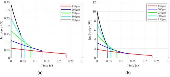
2.1.6 Sample Model Outputs
The above equations were employed to generate theoretical performances for various nozzles at a fixed initial force Fs = 66 N and 𝛼 = 0.45. Piston friction was measured to be 4 N, and an efficiency of 80% was assumed for all nozzles.
28
(a) (b)
Figure 2.2: Theoretical jetting performance over range of nozzle orifice sizes. (a) Force (b) Power
Note that increasing nozzle diameter results in a greater peak power (though the area under the curve remains the same). Thus increasing nozzle diameter may result in deeper tissue penetration, even though the net energy expenditure is the same. Alternatively, the peak power could be increased by increasing Fs. As was noted earlier, it will be important to understand the relationship between these design parameters and tissue penetration in order to implement an ingestible jetting device. (This will be explored in Chapter 3.)
2.2 Experimental Methods
In order to validate the above model so that it may be used with confidence, jetting performance data was collected using a custom jetting system and commercial force transducer.
2.2.1 Testing apparatus
The test-stand was designed to measure jetting force while varying parameters including nozzle orifice size, initial and final spring force, standoff distance, fluid viscosity, angle of incidence, and expelled volume. The main component of the test stand is a hand-held jetting device mounted onto an aluminum rail. Also mounted to the rail is a linear stage and force transducer (see Figure 2.3).
0 0.05 0.1 0.15 0.2 0.25 0.3 Time (s) 0 0.05 0.1 0.15 0.2 0.25 0.3 0.35 Je t F or ce ( N ) Je t P ow er ( W )
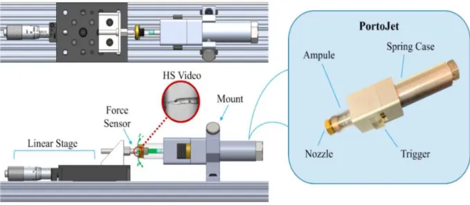
29
Figure 2.3: Testing apparatus used for validating jetting performance, including handheld device, “PortoJet”
The hand-held device, referred to as “PortoJet” can be mounted to and removed from the rest of the test stand easily. This allows for quick refilling of the fluid ampule between trials. The operator may also choose to remove the PortoJet to quickly switch nozzles, and springs if desired.
Load can be applied in the PortoJet either by a pneumatic cylinder or a spring. Use of a pneumatic cylinder is generally preferable for experimentation as spring design inputs can be easily adjusted. For example, the initial force, Fs, applied by the pneumatic cylinder is a function of the cylinder pressure—which can be quickly changed via a pressure regulator. Furthermore, the final spring force (or α-value) of a pneumatic cylinder can be adjusted by simply re-defining the initial position of the pneumatic piston with a spacer. This is far simpler than purchasing a new spring for every load condition.
That said, for the work described in this section, it was only necessary to use one spring force to assess the accuracy of model. Thus a coil spring with Fs = 66 N and α = 0.45 was employed. The different configurations of PortoJet (spring and pneumatic) can be seen in Figure 2.4.
30 (a)
(b)
(c)
Figure 2.4: Diagram showing section views of different versions of the PortoJet (a) With spring. (b) With pneumatic cylinder containing large initial volume, resulting in high α-value. (c) With pneumatic cylinder containing low initial volume, resulting in low α-value.
It was also important to devise a triggering mechanism for the PortoJet which accurately represented that of a potential ingestible device. As such, the trigger needed to withstand large loads, and be able to release these loads quickly. A repurposed Parker quick-disconnect hose fitting, was found to excel at these functions.
(a) (b) (c)
Figure 2.5: Triggering mechanism for PortoJet (a) in the loaded state; (b) in the released state. (c) Parker quick-disconnect fitting on which the triggering mechanism was based [76]
As the sleeve of the fitting is retracted, the ball bearings are allowed to move radially outward. An internal rod, which was axially constrained by the balls, is therefore allowed to translate, and apply a load to the ampule (see Figure 2.5). This design has proven successful in
31
satisfying the loading and release requirements for this work, though other solutions can be found in commercial needleless injectors.
2.2.2 Data collection
The sensor used was a Kistler 9215A piezoelectric force transducer that interfaces with a Kistler 5165A4KH10 LabAmp® Dynamic Laboratory Charge Amplifier. The amplifier was connected to a Windows 10 laptop via Ethernet, and data acquisition was triggered via Kistler’s web-browser based interface. The total acquisition time used for trials was two seconds at a sampling frequency of 20kHz.
Although high-speed video was used during tests, it was deemed to be less than ideal due to the fact that discrete elements of fluid were not observable after jetting initiated. Having said that it is possible to employ high-speed video to verify the total time of a jetting event (as will be shown in Section 4.5). Furthermore, high-speed video is useful for observing the shape of the jet to verify that the jet is indeed columnar and not a spray.
Five replicates were performed for each experimental data point. An ampule volume of 200uL (6 mm diameter and 7 mm stroke) was used for all experiments. 100% deionized water was used for all tests except for those in which fluid viscosity was varied.
2.3 Data Processing
Each data-set, containing 40000 individual time-points, was imported into MATLAB. From there, the maximum load measurement of the data set (assumed to be the peak force applied by the jet) was extracted. Next, the time at which jetting began was determined based on the point at which the measured force exceeded 10% of the peak. Likewise, the time that jetting ceased was marked when the measured force returned below the same threshold.
It was observed, through use of MATLAB’s Fast Fourier Transform function, that data-sets contained high-frequency oscillations at ~35kHz. This was assumed to be sensor noise as the oscillations swung into both the positive and negative range in the time domain. This noise was removed by use of a moving average filter with a half-width of 5ms.
Sensor drift resulted in a linear decay in measured force of approximately 0.1% per millisecond of applied static load (as reported by the manufacturer). This drift is the result of loss in charge within the piezoelectric sensor, which is designed mainly for dynamic loads. As such, compensation was applied to each dataset to correct for the drift.
32
After filtering and drift correction, replicates were combined to create an estimate for mean performance with 95% uncertainty. With the output data, equations from Section 2.1 were used to generate estimates of nozzle efficiency for each orifice size.
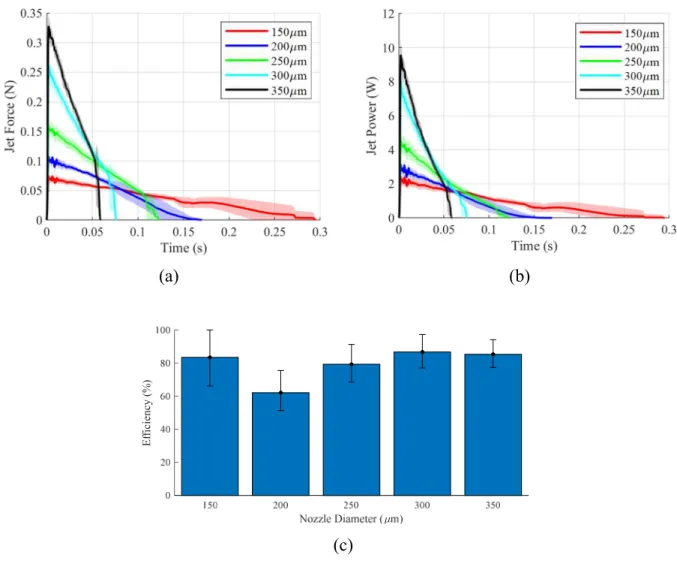
2.4 Experimental Results
Results were plotted for each experiment performed. In each case the nozzle efficiency was deduced by comparison with the theoretical energy input into the jet (i.e. minus piston friction).
(a) (b)
(c)
Figure 2.6: Experimental jetting performance over range of nozzle orifice sizes. (a) Force data – each curve is mean of n=5 replicates, and shaded regions are 95% confidence interval. (b) Resolved experimental power data (c) Nozzle efficiencies given theoretical energy input. NOTE: the experimental data displayed in this figure was collected using a variant of PortoJet developed by Novo Nordisk.
E ff ic ie nc y (% )
33
A comparison between Figure 2.2and Figure 2.6shows that the theoretical model agrees with the measured data. In general, efficiencies fall between 75 and 85% (though, for the 200 µm nozzle, the efficiency was approximately 60%). Nozzle efficiency for any jetting device should be measured prior to implementation of other design features as it can greatly impact performance. It is worth noting that efficiencies can be improved by altering the geometry and surface roughness of the nozzle.
34
3 Tissue Characterization
As noted in Section 1.2, previous ex-vivo work with jetting systems has yielded an extensive body of data on penetration characteristics of jets on skin tissue. However, little to no data exists for jetting in the GI tract. For the purposes of this study, submucosal injection—where a depot is formed directly beneath or within the submucosal tissue—was targeted. Although intramuscular delivery is also feasible in some GI organs, in others, the muscular layer is too thin to support a sizeable payload without risking perforation.
No models that describe the penetration of GI tissue by jets could be located. Aran et al. modeled jet-based penetration of the mucous layer with computational flow analysis [22], but this would likely be insufficient for predicting deeper penetration. Given the complexity of developing an accurate tissue model, this was considered beyond the scope of this thesis. That said, this thesis hypothesizes that power requirements for forming depots in the GI tract are lower than that of skin.
3.1 Ex Vivo Experimental Methods
The goal of the ex vivo experiments is to measure jet interactions with GI tissue, such as delivery efficiency and penetration wound size. These tests were performed on a variety of GI tissues including those of the cheek, esophagus, stomach, large intestine, and rectum. Tissue was tested within six hours of excision. As necessary parameters for delivery were not known initially, a trial and error-based screening was performed to identify a starting point for each tissue type. The data collected from these experiments will provide a preliminary empirical basis for achieving high delivery efficiency, as well as a sense of the impact that jets have on mucosal tissue.
35 3.1.1 Testing Apparatus
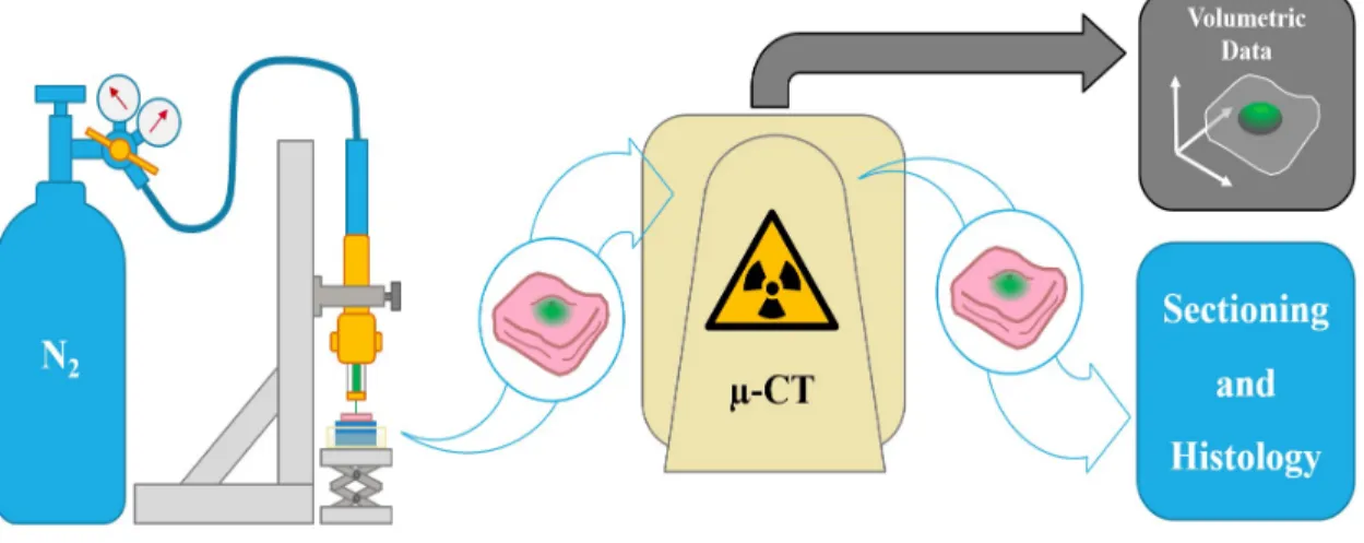
The PortoJet system was used to inject 200uL of contrast agent or histology dye into 5 x 5cm samples of porcine GI tissue. A pneumatic cylinder with an α-value of 0.90 was used for power in all tests. The PortoJet was mounted vertically and tissue was placed directly beneath it on a foam base. The tissue was then brought into contact with the jet nozzle using a scissor jack.
Figure 3.1: Experimental work-flow for ex vivo tissue testing and imaging
3.1.2 X-ray Microtomography
X-ray microtomography (micro-CT) was used to analyze the volumetric efficiency of delivery for each sample. A suspension of 5% wt. barium sulfate was employed as a contrast agent for injection. Tissue samples were scanned within ten minutes of injection so that diffusion was minimized prior to evaluation. The Micro-CT machine captures 2D slices of the tissue with x-ray. A post-processing program was used to reconstruct these slices into a 3D matrix (with high-intensity voxels associated with less light transmission). A threshold is selected manually, and all voxels above this threshold are considered delivered volume.
3.1.3 Histology
A collection of injection trials was performed for histology. In these trials, the tissue was injected with fluorescent dextran. Tissue was frozen at -80ºC and later sectioned at -20ºC in a cryostat with a microtome. Samples were photographed with UV microscopy.
36
3.2 Ex vivo Results
Figure 3.2shows sample micro-CT measurements with successful depots for a variety of tissue types. Depots were observed in all organs except for the esophagus.
(a) (b)
(c) (d)
(e) (f)
(g) (h)
Figure 3.2: Micro-CT images of depots in GI tissue after 200µL jet injections – cross sections on left, volumetric rendering on right. (a)(b) Cheek: dj = 350µm, Fs = 236N. (c)(d) Stomach: dj = 350µm, Fs = 177N.
(e)(f) Colon: dj = 350µm, Fs = 47N. (g)(h) Rectum: dj = 350µm, Fs = 98N.
From the micro-CT images, it is clear that air bubbles (represented by dark-spots), are present in the center of each depot. It is not clear how these bubbles form, although cavitation could be an explanation. While these air pockets do not interfere with the delivery efficiency
5mm
40µL
5mm
160µ
5mm
140µ
37
analysis, they could be of concern from the perspective of safety. As such, further analysis of air cavities in the context of safety will be essential prior to translation of this technology into a clinical or market setting. Use of a different contrast agent could be considered as the barium-sulfate contrast agent is a non-homogeneous suspension rather than a solution (which could affect results). The above micro-CT data was useful for verifying delivery efficiency. However, from this data, it is not possible to discern tissue layering and structures. To that end, histology is more useful. Figure 3.3 shows preliminary histology data on stomach tissue.
(a) (b)
Figure 3.3: Histology of stomach tissue after delivery of 40µL of fluorescently marked dextran. (a) Penetration of the mucosal layer with visible wound. (b) Deep penetration with absorption into of the submucosa visible.
Absorption into the mucosa as well as the submucosa is visible. Also, note the clear penetration wounds, each between 0 and 500µm in diameter and traversing the depth of the entire mucosa. Clearly jets create an observable wound, though this wound is smaller than those seen in mili-needle systems [25]. Also, in these particular trials a volume of 40µL was employed and as a result, depots are less apparent than would be expected for the micro-CT trials (which employed 200µL doses).
Using this histology data, as well as the micro-CT data, a semi-quantitative summary of jetting performance in the GI tract was created (shown in Figure 3.4). This data should provide a sense of which input jetting parameters will result in depots across multiple tissue types.
38
Figure 3.4: Preliminary summary of peak jetting peak pressure performance across multiple tissue types (n = 1 for all points). NOTE: initial pressures were corrected for piston friction losses. Also, despite the diagram, human tissue was not used (but rather porcine tissue).
“Wet shots” refer to trials where most liquid was observed to be on the surface; “Depot” means a visible depot was observed both visually and through micro-CT; and “Perforation” means a clear wound was visible on the serosal side of the tissue and little to no contrast agent was contained within.
Equation (33) was used to calculate the minimum observed peak power requirement for each organ based on the data in Figure 3.4. The results are tabulated in Table 3.1. It is important to note that lower minimum requirements might be possible given smaller nozzle sizes which were not tested in this work.
39
Table 3.1: Summary of minimum peak power requirement for forming depots in GI tissue (inputs corrected with ηn = 0.80)
Organ Min. pk. power to achieve depot
Cheek 52W
Esophagus -
Stomach 26W
Colon 2W
Rectum 7W
The power required to achieve a depot in each tissue type varied widely from organ to organ. However, as hypothesized, the minimum peak requirement in most GI organs appears to be lower than that of skin (i.e. 30W, according to [73]). No depots were observed in the
esophagus. However, depots could be possible at orifice diameters which were not measured. More work is currently underway for the purposes of adding fidelity to each
measurement and covering additional organs (such as the small intestine, which was omitted due to time constraints).
40
4 Device Development
Equipped with an ability to precisely define device jetting power output, as well as a knowledge of jetting power requirements for depot formation in GI tissue, movement towards a device design can begin. The following chapter includes discussion of additional requirements for an ingestible jetting device, implementation of device concepts to meet requirements, and testing that was carried out to evaluate the performance of devices. The work here represents one of many possible ingestible jetting devices and should be considered a proof of concept rather than a final design.
4.1 Engineering Requirements
The first step of any design effort is to define requirements. Up until now, this thesis ha mainly discussed jetting power as a requirement. However, a host of other requirements exist that must be satisfied in order to ensure safe and efficacious implementation of a jetting device.
4.1.1 Avoidance of Obstruction
An obstruction occurs when a device is permanently lodged at some location in the GI tract, disrupting the normal passage of digested matter, and potentially resulting in abrasion, ulceration, tissue necrosis, or the stifling of nutritional uptake. Such obstructions have been reported in studies of slow-release osmotic pumping systems, and are usually attributed to the size of the device. Larger devices are more likely to cause an obstruction resulting in a need for medical intervention [77]. As such, minimizing device size as much as possible is desirable from a safety perspective. As an aside, minimizing device size could also help with adherence, as patients are more likely to adopt a smaller pill [78].
41 4.1.2 Reduction of Trauma
Trauma at the injection site is also of great concern for a jetting device. At the location where the depot is formed, it is clear that the submucosa will be lifted away from the muscularis. Furthermore, there are capillaries running through the submucosa which could be damaged and/or hemorrhage, resulting in infection at the injection site. Aside from infection, if the jet is too strong, it could perforate the muscularis, leading to contamination of the paratenium by gut bacteria (paratenisis). Although there is no data on the above safety issues for GI based jetting systems, it is probable that minimizing jet diameter and payload volume would decrease the risk of trauma. However, the true safety impact of trauma in GI tissue due to jetting is not understood and should be investigated further.
4.1.3 Minimization of Delivery Failures
Delivery failure presents yet another potential safety issue for jetting devices (though one which depends largely on the intended use of the therapeutic). If the jet does not penetrate to the proper depth and deliver the desired dose, this would result in a diminished or non-existent therapeutic effect. There are multiple reasons why delivery failure might occur. For example, food debris could interrupt the transit of the jet or the device orifice could be misaligned relative to the tissue. For certain biologics, such as vaccines or allergens, occasional delivery failure could be permissible. However, for therapeutics where immediate dosing is essential (such as insulin for glycemic control, or epinephrine for anaphylaxis), a missed dose could be life-threatening. There are numerous strategies that could be taken to avoid dosing failures, some of which include tissue contact sensing, self-orientation, and mucoadhesives.
4.1.4 Use of Non-toxic Materials
Acute and chronic material toxicity of the device must be taken into consideration. For example, if the device were made of aluminum, chronic absorption of metabolized device materials could lead to aluminum poisoning [79]. Generally speaking, toxicity concerns can be mitigated by employing materials that are bio-inert or otherwise non-toxic (e.g. titanium, PDMS, PCL, salts, carbohydrates). Polymeric or non-reactive metallic coatings could also be used to protect the device from degradation. Examples of materials thought to be safe for ingestible devices are described by Bettinger et al. [80].
42 4.1.5 Shelf-life
The sponsor of this research specified that it is generally desirable to target a minimum shelf-life of two years for therapeutics. Though the shelf-life typically depends on the payload formulation properties, certain design features of the device itself could also affect shelf life. For example, a degradable component might necessitate that the device be stored with a desiccant. Furthermore, a device containing a sealed gas cavity might require additional measures to stifle gas diffusion. Also, ampule materials could interact with the biologic formulation, resulting in degradation.
4.2 System and Sub-system Concepts
Keeping all of the above requirements in mind, it is possible to select mechanical design concepts for an ingestible jetting device. Though multiple system and sub-system concepts were explored, it was determined that a passively triggered self-orienting device for use in the stomach was most promising. The following section describes the rationale for selecting such a design, as well as design details.
4.2.1 Target Organ: Stomach
The stomach is an attractive target organ for multiple reasons. For one: a device would enter the stomach within seconds of ingestion and remain there for multiple hours thereafter. This means that a timed trigger could be implemented for release of the jet in the stomach, whereas for GI organs distal to the stomach (SI, colon, rectum) there is much greater uncertainty as to when triggering should occur (see Table 1.3).
Aside from timing, the stomach does not transmit acute pain sensation [81], meaning an injection in the stomach would likely go unnoticed by a patient. In the esophagus or cheek, an injection would almost certainly be felt by the patient. Furthermore, stomach tissue is relatively thick, so minor variation in jetting performance due to manufacturing tolerances would be less likely to result in perforation. Lastly, the sterility of the stomach is high due to the presence of stomach acid.
It is also worth noting potential drawbacks of targeting the stomach. For one, delivery in stomach tissue requires a minimum peak power that would cause perforation in distal GI organs. This could pose a safety risk if the device were inadvertently triggered after passage through the
![Table 1.2: Summary of historical needleless devices with estimated peak and delivery pressures [19][21]](https://thumb-eu.123doks.com/thumbv2/123doknet/14674257.557564/11.918.95.829.836.1058/table-summary-historical-needleless-devices-estimated-delivery-pressures.webp)
![Table 1.3: Summary of GI organ physical properties [55][56][57][58][59][60][61][62][63][64]](https://thumb-eu.123doks.com/thumbv2/123doknet/14674257.557564/18.918.111.815.144.400/table-summary-gi-organ-physical-properties.webp)