ADVANCED MONITORING AND ADVICE INTEGRATING
A COMPREHENSIVE SENSOR NETWORK FOR
IMPROVED OPERATIONAL AVAILABILITY
byChang Woo Kang
B.S., Seoul National University, Korea (February 1991) M.S., Seoul National University, Korea (February 1993)
SUBMITTED TO THE DEPARTMENT OF NUCLEAR ENGINEERING IN PARTIAL FULFILLMENT OF THE REQUIREMENTS FOR THE DEGREE OF
DOCTOR OF SCIENCE AT THE
MASSACHUSETTS INSTITUTE OF TECHNOLOGY February, 1998
© Massachusetts Institute of Technology, 1998 All rights reserved
Signature of Author ...
/
Department of Nuclear EngineeringFebruary 9, 1998 .-
0-Certified by
--rh ofessor Michael W. Golay Thesis Supervisor
Certified by ... . .. ... ..
Professor Neil E. Todreas Thesis Reader
Accepted by ... ... Professor Lawrence M. Lidsky Chairman, Department Committee on Graduate Students
3
-B~LI8RARIIb
Advanced Monitoring and Advice Integrating a Comprehensive Sensor
Network for Improved Operational Availability
by
CHANG WOO KANG
Submitted to the Department of Nuclear Engineering on February 9, 1998 in partial fulfillment of the
requirements for the Degree of Doctor of Science in Nuclear Engineering
Abstract
This research broadens the prime concern of nuclear power plant operations from safe performance to both economic and safe performance through monitoring and advice. First, rotating machines such as turbine generators and reactor coolant pumps are identified as main contributors for the lost availability through the review of pressurized water reactor (PWR) forced outage records. The integrated architecture utilizes comprehensive sensor networks incorporating modern signal processing systems, advisory systems for sensor validation, and advisory systems for the intelligent diagnosis and maintenance (D&M).
For the development of comprehensive sensor networks for complex target systems, an integrated method incorporating a structural system hierarchy and a functional system hierarchy, a fault-symptom matrix, sensor selection criteria, a sensor installation feasibility study, and advanced instrumentation techniques is formulated. Such advanced instrumentation techniques reflect the state of the art in advancement of data acquisition, data processing, and data integration techniques. Once the sensor types and locations are selected definitively, they are incorporated into drawings using a computer aided design tool (e.g. AutoCAD) program in order to make sure that it would be possible to install the comprehensive set of recommended sensors on each specific component studied.
The second major part of this study is the development of an intelligent D&M advisory system integrating a comprehensive sensor network. This advisory system employs a Bayesian Belief Network (BBN) as a high level reasoning tool for incorporating inherent uncertainty for use in probabilistic inference. It is demonstrated that a rule-based knowledge representation is simply a special case of a general BBN by showing how the general BBN can be reduced to a rule-based representation. The presented major steps for constructing the BBN based generic inference algorithms are applied to systematic elicitation and synthesis of various levels of experts' knowledge. Prototype D&M algorithms are represented explicitly through topological symbols and links between them in a causal direction.
This D&M advisory system is set up with an easy-to-learn, user-friendly, man-machine interface and modern graphics for efficient operator interactions. As new pieces of evidence from sensor networks developed are entered into this system, it provides operational advice concerning both availability and safety so that the operator is able to
determine the likely failure modes, diagnose the system state, locate root causes, and take the most advantageous action. Thereby, the comprehensive monitoring supported advice improves operational availability.
Thesis Supervisor: Michael W. Golay Title: Professor of Nuclear Engineering
Acknowledgements
Three and half years went by so fast, but in my heart there remain many memories to cherish and lots of gratitude to express to many individuals. Their support and company not only professionally enriched my stay at MIT but also made it very enjoyable.
First, I wish to express my deep gratitude to my advisor, Professor Michael W. Golay, for his insightful guidance and unending support through the entire research of this thesis. Without his continuous encouragement and creative inspiration, this fulfillment would
never accomplish the best of me.
I have the utmost respect for Professor Allan Henry professionally and personally, and can never forget his benevolent smiles during his wonderful lectures and his sincere advice during my preparation of the General Exam. Many thanks are directed to Professor Neil Todreas for serving as my thesis reader. His critical feedback and outstanding instruction have been of great value to this thesis. In addition, I would also thank my thesis committee members, Professors Ronald Ballinger and Professor John Meyer, and Dr. John Bernard for their time and efforts.
Special thanks also go to Mr. Byongseop Kim, the project manager at KEPRI, for his clear requirements upon our project and his considerate assistance. I am really grateful to Mr. Stephen Rosen and Mr. Brian Baldwin at South Texas Power Station, Ms. Laurie Wetherell and Mr. Joseph Lamoureux at Pilgrim Power Station, and Mr. Steve Ball and Mr. Stew Friedman at Seabrook Power Station for their technical support and review on the sensor network development. I am indebted to Prof. W.T. Thomson at Electrical Engineering of the Robert Gordon University in Scotland, Prof. F.V. Jensen at Computer Science of Aalborg University in Denmark, and Prof. P. Szolovits at EECS of MIT for their willingness to release the output and experience of their research, which have been of great value to the project.
Now I should offer my gratitude to all my friends, and colleagues at MIT. I wish to express my thanks to Mr. Namsung Ahn, Dr. Sangman Kwak, Sungmin (Hyong), Chihayng (Hyong), Seokwon, and Korean Catholic community of Boston for their companionship through days at MIT. Yu Sui, Kevin Clarno and Jongbeom Lee, KEPRI engineer, played valuable roles in the collaboration in this research through many productive discussions. Their unnoticed efforts were greatly appreciated. I also enjoyed working with my colleagues, Jon Lunglhofer, Hideki Masui, Scott Palmtag, Tom Moore, Xinhui Chen, and Tsu-Mu Kao.
I also wish to extend my thanks to the Korean Government, ABB-CE, and KEPCO for their financial supports for my study. This little fruition is dedicated to my mentor, Professor Chang Hyun Chung at Seoul National University as a token of my esteem.
Finally, I owe my deepest gratitude and respect to my parents, for their tremendous encouragement, understanding, prayers, and love to me through all years.
DEDICATED TO
my parents Kang, Yun-Won and Lee, Young-Lee,
TABLE OF CONTENTS
Page Abstract 2 Acknowledgments 4 Table of Contents 6 List of Figures 10 List of Tables 14 Nomenclature 16 Chapter 1. Introduction 18 1.1 Motivation 18 1.2 Objectives 181.2.1 Method Formulation for Developing Sensor Networks 19 1.2.2 Comprehensive Sensor Network Development at the Design Stage 19 1.2.3 Sensor Network Supported Advisory System Development 20
1.3 Overview 22
1.4 Organization 25
Chapter 2. Target Systems 29
2.1 Selection Criteria 29
2.2 Lost Availability Contribution of Plant Equipment 30 2.3 Characteristics of Target Systems
2.3.1 Turbine Generator (TG) 33
2.3.2 Reactor Coolant Pump (RCP) 37
Chapter 3. Integrated Method for Comprehensive Sensor Network Development 40
3.1 Introduction 40
3.2 Conventional Methods for Determination of Sensor Networks 41 3.3 System Oriented Hierarchy Based Approach Integrating Advanced
Instrumentation Techniques 42
3.3.1 Structural System Hierarchy (SSH) and Functional System
Hierarchy (FBH) 43
3.3.2 Fault-Symptom Matrix 45
3.3.3 Sensor Selection Criteria 46
3.3.4 Sensor Installation Feasibility Study 47
3.3.5 Advanced Instrumentation Techniques 47
3.4 Application of SSHs and FSHs into Sensor Network Development for
Target Systems 61
3.4.1 Application into the Turbine Generator 61
Chapter 4. Modern Sensor Based Condition Monitoring Techniques for Target
Systems 87
4.1 Scope of Condition Monitoring 87
4.2 Modern Process Parameter Condition Monitoring Techniques 89 4.3 Modern Status Parameter Condition Monitoring Techniques 91
4.3.1 Vibration Analysis 91
4.3.2 Wear Debris Analysis 97
4.3.3 Motor Current Analysis 99
4.3.4 Partial Discharge Analysis 103
4.3.5 Rotor Flux Monitor 105
4.3.6 Shaft Voltage Detector 107
4.3.7 Generator Core Condition Monitor 107
4.3.8 Fiber Optic End-Turn Winding Vibration Monitor 108
4.3.9 Torsional Vibration Monitor 111
4.3.10 Hydrogen Gas Purity Sensor 113
4.3.11 Hydrogen Dew Point Monitor 113
4.3.12 Hydrogen Leakage Detector 114
4.3.13 Water Conductivity Detector 115
Chapter 5. Development of Comprehensive Sensor Networks 116
5.1 Introduction 116
5.2 Architecture of Plant Wide Condition Monitoring System Networks 117 5.3 Sensor Arrangements for Advanced Condition Monitoring in the Turbine
Generator (TG) 117
5.3.1 Sensor Arrangement for the TG Exterior 119
5.3.2 Sensor Network for the Main Generator 121
5.3.3 Sensor Network for the TG Lubrication Oil System 123 5.3.4 Sensor Network for the Stator Coil Cooling Water System 125 5.3.5 Sensor Network for the Hydrogen Cooling Auxiliary System 126 5.3.6 Sensor Network for the Gland Seal System 128 5.3.7 Sensor Network in Generator Core and Frame 130 5.4 Sensor Arrangements for Advanced Condition Monitoring in the RCP 130 5.5 Priority Recommendations of Sensor for Use in On-line Monitoring 133 5.6 Strategy for Sensor Set Determination Utilized in a Nuclear Power Plant 136
Chapter 6. Bayesian Belief Networks Based Expert System 138
6.1 Introduction 138
6.2 Expert System Applications 138
6.3 Bayesian Belief Networks Based Approach 140
6.3.1 Motivation 140
6.3.2 Overview 141
6.3.3 Fundamental Theory 142
6.4 Comparison Between Rule-based and Bayesian Belief Network (BBN)
Based Expert Systems 146
6.4.2 Knowledge Representation and Complexity Management 147
6.4.3 Uncertainty Management 149
6.4.4 Decision Making 149
6.4.5 Inference Engine and Mechanism 150
6.4.6 Modification, Refinement and Verification of Knowledge 151
6.4.7 Knowledge Acquisition 152
6.5 Example BBN Based Diagnosis and Management (D&M) Model 153 6.6 Reduction to a Rule-based Representation of a General BBN 157
Chapter 7. Selection of Expert System Shell 159
7.1 Selection Criteria 159
7.2 Review of Commercially Available Shells 161
7.2.1 BBN-based Expert System Shells
7.2.2 Rule-based Expert System Shells 163
7.3 Features of the HUGIN Expert System Shell 165
Chapter 8. Integration of the Bayesian Belief Network Based Inference Algorithm 168
8.1 Introduction 168
8.2 Advisory System Uses 168
8.3 Integrated Architecture for an Advisory System for the Intelligent Diagnosis and Maintenance Integrating a Comprehensive Sensor Network 169
8.4 Reasoning Inference Method 172
8.4.1 Information Flow Reasoning 172
8.4.2 Causality Flow Reasoning 174
8.5 Formulation of the BBN Based Generic Diagnosis Inference Algorithm 176 8.5.1 Structural System Hierarchy and Functional System Hierarchy 176
8.5.2 Refined Causal Network 178
8.5.3 Bayesian Belief Network with Inference Engine 179 8.5.4 Bayesian Influence Diagram with Inference Engine 181
8.6 Applied Utility Principle 182
8.7 Prototype Decision Making Model 185
8.8 Prototype Predictive Mode Model 186
Chapter 9. Implementation of Intelligence Diagnosis and Maintenance Advisory
System 188
9.1 Introduction 188
9.2 Operator Interface Module 188
9.3 Implementation of the BBN Based Intelligence Diagnosis and
Maintenance Network 190
9.3.1 Probabilistic Diagnostic Network for the TG Bearing Component 191 9.3.2 Probabilistic Diagnostic Network for the Generator Stator
Windings with Auxiliary Cooling Systems 215
9.3.3 Probabilistic Diagnostic Network for the Reactor Coolant Pump 220 9.3.4 Probabilistic Predictive Network for the Generator Core Vibration 228 9.4 Representation of Abnormal Procedures Using the BBN Formalism 231
9.5 Summary
Chapter 10. Testing and Plan for Validation 238
10.1 Introduction 238
10.2 Proposed Validation Strategy 238
11.3 Plan for Model Refinement 240
Chapter 11. Conclusions 243
11.1 Results of This Study 243
11.2 Suggested Future Work 245
References 247
Appendices 251
Appendix A. Conditional Probability and Utility Values for the Network Shown
in Figure 9.4 (for the Turbine Generator Lubrication Oil System) 251 Appendix B. Conditional Probability and Utility Values for the Network Shown
in Figure 9.14 (for the Generator Stator Winding System) 256 Appendix C. Conditional Probability and Utility Values for the Network Shown
in Figure 9.17 (for the Reactor Coolant Pump Bearing Component) 259
List of Figures
Number Caption Page
2.1 Relationships of Availability, Maintainability, and Reliability 29 2.2 Leading Causes of Turbine Generator Availability Loss 36 2.3 Leading Causes of Reactor Coolant Pump Availability Loss 37
3.1 Process Diagram for Sensor Network Development 50
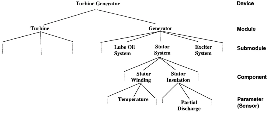
3.2 Elements of a Structural System Hierarchy (SSH) in the Turbine
Generator 51
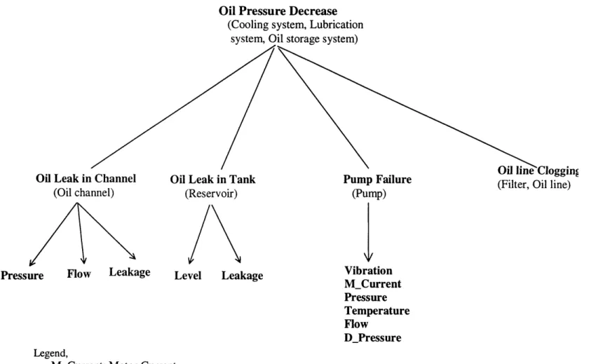
3.3 SSH for the Turbine Lubrication Oil System 52
3.4 FSH for the Turbine Lubrication Oil System 53
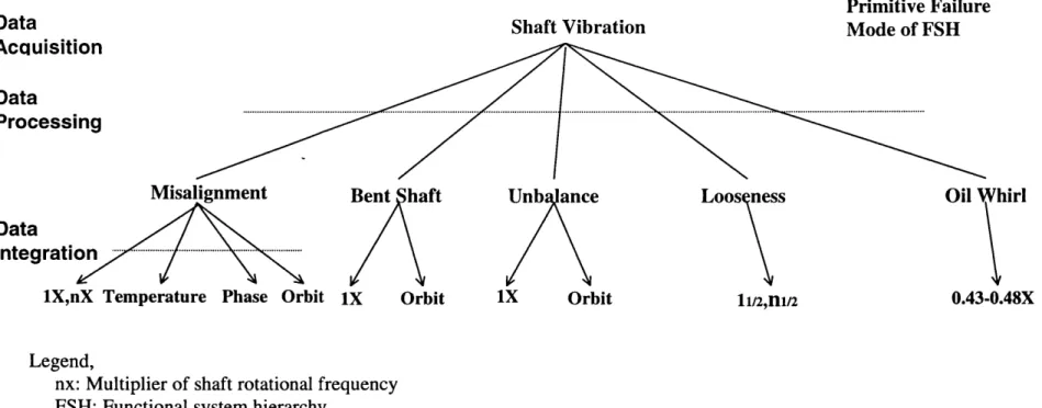
3.5 FSH and Further Breakdown by Use of Advanced Instrumentation
Techniques in Shaft Vibration Analysis 59
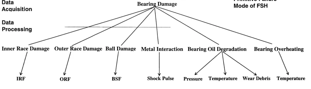
3.6 FSH and Further Breakdown by Use of by Advanced Instrumentation
Techniques in Bearing Damage Analysis 60
3.7 SSH of the Generator Stator Winding System 63
3.8 FSH of the Generator Stator Winding System 64
3.9 SSH of the Generator Auxiliary Hydrogen Cooling System 65 3.10 FSH of the Generator Auxiliary Hydrogen Cooling System 66
3.11 SSH of the Turbine Gland Seal System 69
3.12 FSH of the Turbine Gland Seal System 70
3.13 SSH of the Generator Rotor System 72
3.14 FSH of the Generator Rotor System 73
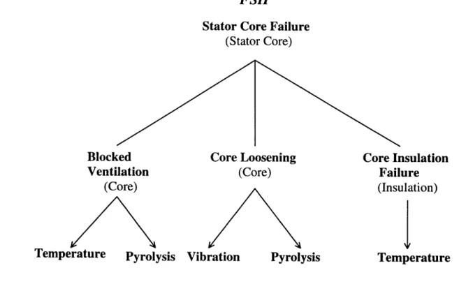
3.15 SSH and FSH of the Generator Stator Core Frame 74
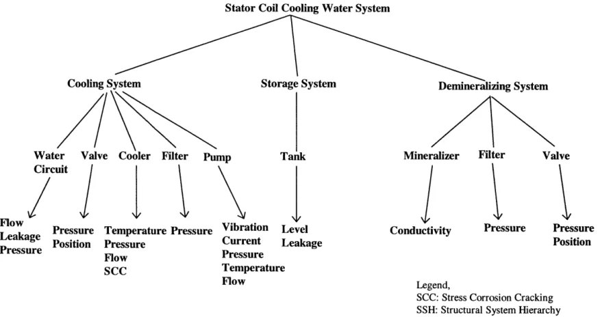
3.16 SSH of the Generator Stator Coil Cooling Water System (SCCW) 75
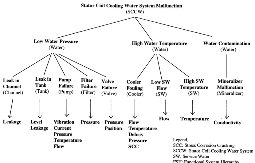
3.17 FSH of the Generator SCCW 76
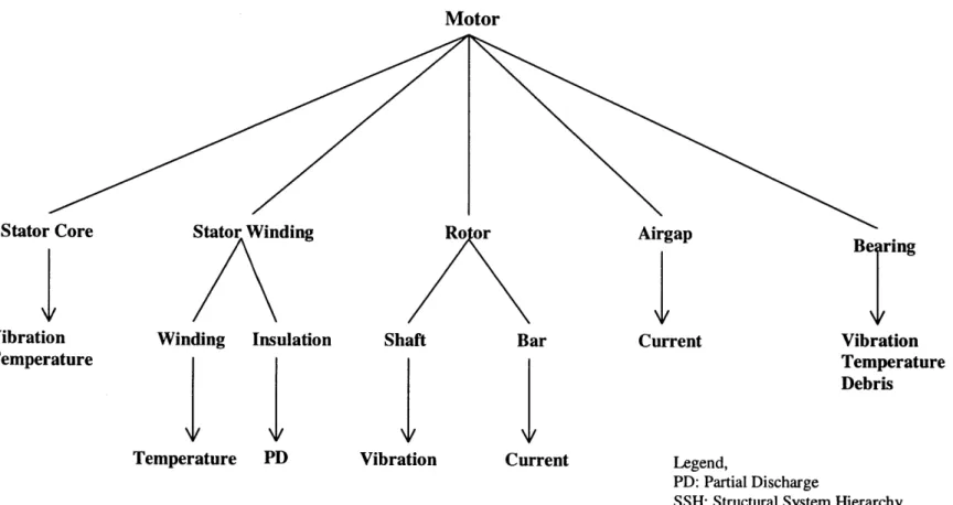
3.18 SSH of Motor in the Reactor Coolant Pump (RCP) 77
3.19 FSH of Motor in the RCP 78
3.20 FSH and Further Breakdown by Use of Advanced Instrumentation Steps
in RCP Bearing Analysis 79
3.21 SSH of the RCP Lubrication Oil System 80
3.22 FSH of the RCP Lubrication Oil System 81
3.24 FSH of the Seal with Seal Injection Flow System 86 4.1 Data Processing Equipment for Advanced Vibration Spectrum Analysis 93
4.2 Motor Failure Diagram 100
4.3 Current Transformer Installation for Motor Current Monitoring 101 4.4 Schematic Diagram of On-line Partial Discharge Monitoring System 104
4.5 Airgap Search Coil Installation 105
4.6 Generator Flux Probe Installation 106
4.7 Schematic Diagram of Generator Core Condition Monitor (GCCM) 109 4.8 Operating Principle of Fiber Optic Vibration Sensor 110 4.9 Construction and Installation Locations of Fiber Optic Vibration Sensor 112
5.1 Schematic Diagram of the Sensor Network for Condition Monitoring
on the Turbine Generator Exterior 120
5.2 Schematic Diagram of the Sensor Network for Condition Monitoring
in the Main Generator 122
5.3 Schematic Diagram of Sensor Network for Condition Monitoring in the
TG Lubrication Oil System 124
5.4 Schematic Diagram of Sensor Network for Condition Monitoring in the
SCCW 125
5.5 Schematic Diagram of Sensor Network for Condition Monitoring in the
Hydrogen Auxiliary Cooling System 127
5.6 Schematic Diagram of Sensor Network for Condition Monitoring in the
Hydrogen-side Gland Seal System 128
5.7 Schematic Diagram of Sensor Network for Condition Monitoring in the
Air-side Gland Seal System 129
5.8 Schematic Diagram of Sensor Network for Reactor Coolant Pump
Condition Monitoring 132
5.9 Schematic Diagram of Sensor Network for RCP Motor Condition
Monitoring 133
6.1 Applications of Expert Systems in Many Fields 139
6.2 A Simple Bayesian Network (I) Illustrating Conditional Independence 143
6.3 A Simple Bayesian Network (II) and its Logic 145
6.5 Example of the Bayesian Belief Network (BBN) Based Diagnosis and
Maintenance Network for the Turbine Bearing 155
6.6 Rule Representation Using the BBN Formalism 158
7.1 Schematic Structure Describing Stages of Development and Use of the
HUGIN Expert System Shell 166
8.1 Integrated Architecture for the Intelligent Diagnosis and Maintenance
Advisory System Integrating the Comprehensive Sensor Network 171
8.2 A Fragment of Information Flow Reasoning 172
8.3 A Fragment of Causality Flow Reasoning 174
8.4 Bayesian Belief Networks Based Generic Diagnosis Inference Algorithm
Formulation Procedure 177
8.5 Decision Making Model for Explaining the Principle of the Utility Concept 183 8.6 Implicative Prototype Decision Making Model Network Imbedded within
the Advisory System 186
8.7 Prototype Network for the Advisory System in the Predictive Mode 187 9.1 Operator Interface Module for Editing the Network 189 9.2 Operator Interface Module for Displaying the States and their Respective
Probability Values for the Network's Nodes 190
9.3 Probabilistic D&M Nodal Network for the Bearing in the Turbine
Generator 194
9.4 Probabilistic D&M Nodal Network for the TG Lubrication Oil System 203 9.5 Probabilistic D&M Nodal Network for the Turbine Lubrication Oil Pump 204 9.6 Execution Flow in Task I (Nominal Case) of the Network Shown in
Figure 9.3 206
9.7 Execution Flow in Task I (Pessimistic Case) of the Network Shown in
Figure 9.3 207
9.8 Execution Flow in Task II (Nominal Case) of the Network Shown in
Figure 9.3 208
9.9 Execution Flow in Task II (Pessimistic Case) of the Network Shown in
Figure 9.3 209
9.10 Execution Flow in Task III (Nominal Case) of the Network Shown in
9.11 Execution Flow in Task III (Pessimistic Case) of the Network Shown in Figure 9.3
9.12 Execution Flow in Task IV (Nominal Case) of the Network Shown in Figure 9.3
9.13 Execution Flow in Task IV (Pessimistic Case) of the Network Shown in Figure 9.3 9.14 Probabilistic D&M System 9.15 Probabilistic D&M 9.16 Probabilistic D&M Cooling System 9.17 Probabilistic D&M Bearing 9.18 Probabilistic D&M System
Nodal Network for the Generator Stator Winding
Nodal Network for the Nodal Network for the
Generator SCCW
Generator Hydrogen Auxiliary
Nodal Network for the Reactor Coolant Pump (RCP)
Nodal Network for the RCP Bearing Lubrication Oil
Probabilistic D&M Nodal Network for the Probabilistic D&M Nodal Network for the
RCP Motor RCP Seal 9.21 Probabilistic D&M Nodal Networks for the RCP Shaft
9.22 Probabilistic Predictive Network for the Generator Core Vibration in the Operator Interface Module
9.23 Task Execution Flow of the Predictive Mode Network Shown in Figure 9.22
9.24 Rule-Based Procedure TG-I Representation Using the BBN Formalism 9.25 Task Execution Flow of the Network Shown in Figure 9.24
9.26 Rule-Based Procedure TG-II Representation Using the BBN Formalism 9.27 Task Execution Flow of the Network Shown in Figure 9.26
9.28 Rule-Based Procedure RCP-I Representation Using the BBN Formalism 9.29 Task Execution Flow of the Network Shown in Figure 9.28
211 212 213 217 218 219 223 224 225 226 227 228 230 232 234 234 235 236 237 9.19 9.20
List of Tables
Number Caption Page
2.1 Lost Availability Contribution Ranking of PWR Plant's
Systems/Components (1990-1995) 31
3.1 Fault-Symptom Matrix for Bearing, Shaft and Lubrication Oil System 57
3.2 Sensor Selection Criteria 58
4.1 Comparison of Vibration Sensors 92
4.2 Vibration Diagnostic Chart 96
5.1 Nomenclature for Sensor Names 118
5.2 Sensor Locations and Types in the Turbine Generator Exterior 119 5.3 Sensor Locations and Types inside the Generator 121 5.4 Sensor Locations and Types in the Reactor Coolant Pump 131
5.5 Recommended Order of Priority in Measuring the Specific Parameter with
Multiple Choices of Suggested Sensors 134
7.1 Comparison of Alternative BBN Based Expert System Shell Features 162 7.2 Comparison of Alternative Rule-based Expert System Shell Features 164 8.1 Conditional Probability Table from Eliciting Expertise Linking a 3 State
Sensor (S) and a 3 State Failure Mode (F) in terms of P(F/S) 180 8.2 Conditional Probability Table Linking a 3 State Sensor (S) and a 3 State
Failure Mode (F) in terms of P(S/F) 181
9.1 Node Nomenclature of Figure 9.3 192
9.2 Node Nomenclature of Figure 9.4 193
9.3 Node Nomenclature of Figure 9.5 193
9.4 Conditional Probability and Utility Values in the Nominal Case for
the Network Shown in Figure 9.3 195
9.5 Conditional Probability and Utility Values in the Pessimistic Case for
the Network Shown in Figure 9.3 199
9.6 Results Task I to the Network for the Turbine Generator Bearing System
in Figure 9.3 214
9.7 Node Nomenclature of Figure 9.14 215
9.8 Node Nomenclature of Figure 9.15 216
9.9 Node Nomenclature of Figure 9.16 216
9.10 Node Nomenclature of Figure 9.17 220
9.11 Node Nomenclature of Figure 9.18 221
9.12 Node Nomenclature of Figure 9.19 221
9.13 Node Nomenclature of Figure 9.20 221
9.15 Conditional Probability and Utility Values for the Network Shown
in Figure 9.22 229
9.16 Conditional Probability and Utility Values for the Network Shown
in Figure 9.24 233
9.17 Utility Values for the Network Shown in Figure 9.26 235 9.18 Utility Values for the Network Shown in Figure 9.28 236
Nomenclature
ACC Accelerometer
A/D Analog-to-Digital
API Advanced Program Interface
AS Air-Side
BBN Bayesian Belief Network
BID Bayesian Influence Diagram
BSD Bearing Ball Sphere Defect
CAD Computer Aided Design
CBM Condition Based Maintenance
CCWS Component Cooling Water System
CF Certainty Factor
CM Condition Monitoring
CPT Conditional Probability Table D&M Diagnosis and Maintenance
DCS Data Communication System
EFMDAS Electrical Fault Monitoring Data Acquisition System
EHC Electro-Hydraulic Control
EM Electro Magnetic
ERTS Electronic Rotor Temperature Sensor
ES Expert System
FD Bearing Train Defect
FFT Fast Fourier Transform
FMEA Failure Mode and Effect Analysis
FOT Forced Outage Time
FSH Functional System Hierarchy
FT Fault Tree
GCCM Generator Core Condition Monitor
HP High Pressure
HPM Hydrogen Purity Meter
HS Hydrogen-Side
HUGIN Handling Uncertainty in General Inference Network
HX Heat Exchanger
I&C Instrumentation and Control
INEL Idaho National Engineering Laboratory INPO Institute of Nuclear Plant Operations
IRD KNGR KP LAN LFM LOCA LP MFP MTBF MTTR NPP NPRDS NRC ORD PDA PP PWR RCP RF RTD RXD SCCW SOA SOT SSH SW TBWD TC TG TSD TVMDAS WDA
Bearing Inner Race Defect Korean Next Generation Reactor Keyphasor (Phase Reference Probe) Local Area Network
Logic Flowgraph Methodology Loss of Coolant Accident
Low Pressure
Main Feedwater Pump Mean Time between Failures Mean Time to Repair
Nuclear Power Plant
Nuclear Plant Reliability Data System Nuclear Regulatory Commission Bearing Outer Race Defect Partial Discharge Analysis Proximity Probe
Pressurized Water Reactor Reactor Coolant Pump Radio Frequency
Resistance Temperature Detector Rotor Expansion Detector
Stator Coil Cooling Water Auxiliary System Spectrometric Oil Analysis
Scheduled Operating Time Structural System Hierarchy Service Water
Thrust Bearing Wear Detector Thermocouple
Turbine Generator Turbine Stress Detector
Torsion Vibration Monitoring Data Acquisition System Wear Debris Analysis
Chapter 1. Introduction
1.1
Motivation
As increased productivity is necessary to remain competitive in all areas of machinery process operation, attaining a high level of power plant operational availability is one of the most importance issues facing the nuclear power industry. The nuclear power industry must be willing to expand the goal of each plant from safe performance to both safe and economic performance. This is due to the fact that forced outages or power reduction constitute significant financial losses and possible degradation of power system reliability to unacceptable levels. For example, the financial loss caused by one day of forced outage amounts to about $ 0.7 million for a 1300 MW nuclear power plant. In addition, the degradation of system integrity due to forced outages may increase even further financial losses.
Consequently, it is of vital importance to reduce the probability of forced outages and improve the maintenance schedule and procedure. There is a strong interest in the implementation of modern condition monitoring and intelligent maintenance. The capability to provide early detection and diagnosis of component deterioration is an essential part of any effective maintenance program.
Therefore, the work reported here is concerned with use of on-line monitoring and advice to improve nuclear power plant operational availability. It is focused upon new pressurized water reactors (PWRs), such as is envisioned for the Korean Next Generation Reactor (KNGR).
1.2
Objectives
The work reported here examines operational availability improvements through monitoring and advice. The key objectives are categorized in this section. They are aimed at constituting the entire form of a comprehensive sensor network integrated advisory system at the design stage in a systematic way. It is in this context that we examine the techniques now available and movement of the state of the art toward on-line intelligent condition based monitoring, diagnosis, and maintenance.
1.2.1 Method Formulation for Developing Sensor Networks
The rapid advancement of powerful monitoring devices and computers permits us to configure an advanced on-line sensor network as a foundation for efficient plant monitoring and diagnosis. This technical trend and increasing competition motivates an interest in plant operations for both increased safety and operational availability.
In designing a monitoring system a study should reveal which components make dominant contributions to lost operational availability of the PWRs. Those components with high failure rates and those failures causing long duration outages are the prime culprits for causing the plant's unavailability. When designing equipment, it is desirable to consider condition monitoring in conjunction with failure mode studies. Thus, for any important component each failure mode should be identified and a number of possible methods for detecting the onset of failure should be considered. However, most of the equipment in a nuclear power plant have very complex functions and interrelationships with other subordinate components. As the complexity and interrelationship of subordinate components increases, it becomes more difficult to employ a proper set of sensors and advanced data processing techniques in a systematic way. To that point, there has been no well-established systematic method in common use for developing comprehensive sensor networks considering all steps of modem data processing techniques for complex systems. That situation motivates the work reported here to develop a systematic approach for analyzing failure modes and determining associated sensor sets incorporating modern data processing equipment.
1.2.2 Comprehensive Sensor Network Development at the Design Stage
These days, special instrumentation and powerful computer supported maintenance systems are finding their ways into nuclear power plants. The cumulative effect of using a monitoring and diagnostic system is expected to be a significantly improved operational availability of the power plant in addition to detailed understanding of system conditions by the plant operation staff. Thus, an integrated architecture for systematically performing on-line condition monitoring and intelligent diagnostic maintenance should be configured.
As prerequisite work, we should perform a state of the art review on modern sensor processing technologies used in other industries such as aerospace, chemical process and automated manufacturing for evaluating the feasibility that may also be imbedded useful for the nuclear power industry. Moreover, special instrumentation and powerful computer supported maintenance systems are finding their ways into nuclear power plants. Currently, there are many newly developed proprietary devices on the market that may be used for advanced condition monitoring. Most of these devices are usually applied after a plant component has been installed. It very difficult and expensive to add instrumentation to a plant once it has been built. Rarely is equipment supplied which has been designed with the presence of condition monitoring devices as a basic design consideration. A designer has incentives to install an abundant sensor network into the initially constructed plant. Thus, this study places a great emphasis upon the value of inclusion of modern condition monitoring into the requirement of design equipment, and it expands a concern for the development of intelligent systems in order to integrate process and control with condition-based maintenance (CBM). A modern condition monitoring can ensure that all actions and decisions are made based upon substantial and corroborated diagnostic information, thereby eventually leading to financial gains.
1.2.3 Sensor Network Supported Advisory System Development
Even though a comprehensive monitoring system is configured through this study, effective maintenance and troubleshooting of complex mechanical equipment is still a formidable task. Considerable diagnostic information available from this monitoring system is not always correlated or otherwise analyzed and presented in a form which can be well suited for aiding the operator's judgement. Technical staff should interpret a large amount of available information, such as data from sensors or data processing equipment, promptly and efficiently. In practice, it is very difficult to establish cause and effect relationships because of the non-linear nature of complex mechanical systems. In this situation, operators must use subjective judgement, based upon their experience and training, in prioritizing alarms and analyzing diagnostic conditions.
Expert systems (ES) are known to be computer-based systems employing human knowledge to solve problems that are thought to require human expertise. Applications of expert systems in many fields of study have grown very rapidly during the last decade or so. Automating some of the decision making tasks to be performed on a regular basis, thereby relieving the operator to do more demanding tasks can reduce the burden of the operator. A knowledge-based advisory system incorporated into a modern condition monitoring system is recommended for capturing the decision logic of diagnosis and maintenance. This advisory system transforms information from comprehensive sensor networks into the operational advice that is useful to safe and economic operation.
However, most of the knowledge-based systems employed in the area of diagnosis have used a shallow knowledge of the system, which link an observed phenomenon to an individual system fault itself. In the nuclear power industry existing monitoring systems have been designed mainly from the safety standpoint. In the diagnostic advisory system their corresponding safety related operational procedures are usually represented by a set of production rules that express deterministic problem solving domains or straightforward stochastic problem solving domains supplemented with an uncertainty factor. This is usually done with shallow understanding or heuristics of the causal evolution of system faults.
In most practical applications, however, uncertainty is inherent factor to be considered, not an exception. There are various sources of uncertainty. The observations may be uncertain, the information may be incomplete, and the relations in the domain may be of a non-deterministic type. Thus, there is a need for expert systems that deal with uncertain situations. Moreover, in a complex, sophisticated problem solving domain, the use of deterministic rules often forces the domain expertise descriptions into an inappropriate representation because they are characterized by a large collection of rules based upon empirical associations. Trouble shooting in a rule-based system typically involves simple retrievals of stored candidate lists indexed by failure symptoms. The availability-driven diagnosis involves an inherently increasing uncertain due to greater system complexity than is associated with safety-related monitoring.
Although this can result in fast efficient diagnoses for deterministic fault identification, it is not suitable for representing structural and functional domain
knowledge in a complex system, which represents the interconnection and the behavior among subordinate components in a complex system. A complex mechanical system mechanism involves complicated cause-effect interactions between many subordinate components. Skilled management is required in order to achieve efficient performance. This requires considerable experience and a sound understanding of the cause-effect relationships governing the complex processes of interest. Finally, this broadened concern motivates the work reported here to employ high level reasoning tools for incorporating inherent uncertainty for analysis of complex problems.
1.3 Overview
The work reported here broadens the prime concern of nuclear power plant operations from safe performance to both economic and safe performance. We examine improvements in terms of the instrumentation and control area. The framework of an integrated architecture for performing modern on-line condition monitoring and intelligent maintenance for operational availability improvement is configured in this work. This integrated architecture is composed of comprehensive sensor networks incorporating modern signal processing systems, advisory systems for sensor validation, and advisory systems for intelligent diagnosis and maintenance. Because the degree of validity of sensor readings proves to be a major factor in determining the accuracy of information which will be provided for diagnosis and maintenance advice, this advisory system is required to perform sensor validation and data file configuration for every diagnostic advisory system input. In an advisory system for intelligent diagnosis and maintenance, the information from the sensor validation advisory system is correlated, analyzed, and presented in a form that can be well suited for aiding the operator's decisions. We conclude that many of these efforts, use of a condition monitoring system, intelligent sensor validation advisory system, and intelligent diagnosis and maintenance advisory system are directed at perfecting on-line capabilities for improved availability and efficiency of the power plant.
The work reported here includes two major parts for plant availability improvement: 1) A modern on-line condition monitoring system is developed for early
fault detection in complex machines. 2) Assuming that there are valid sensor readings available through sensor validation advisory systems, an advisory system for intelligent diagnosis and maintenance is developed.
First, it is shown which components have had dominant influences upon major lost availability in the recent operation of PWRs in United States. Complex rotating machines such as turbine generators and reactor coolant pumps are identified as main contributors for the lost availability through the review of plant forced outage records. They are known to be very complex systems composed of various mechanical and electrical components. Insufficient understanding of system characteristics, for example, due to its complexities, usually renders development of an efficient monitoring condition more difficult. Demands for improving availability facilitated by instrumentation and control (I&C) make the development of a sensor network subject to a requirement for profound understanding of system features and functionality. The sensor network development in the complex system should be based upon sufficient understanding of essential system attributes such as structure, function, and interrelationships. However, a conventional analytical method called Failure Modes and Effect Analysis (FMEA) for sensor network development has proven to be inadequate as system complexities, interrelationship of subordinate components and the number of the utilized sensor sets grow.
For the development of the comprehensive sensor networks for complex target systems, an integrated method incorporating a structural system hierarchy and a functional system hierarchy, a fault-symptom matrix, sensor selection criteria, a sensor installation feasibility study, and advanced instrumentation techniques is formulated. The design method suggested here also describes the rationale for the allocation of sensors for a particular monitored component. The nature of this abstraction is dictated by the needs for determination of the needed sensor types. It emphasizes an approach using structural and functional system abstraction for developing sensor networks that are capable of reflecting the aspects of the system's performance and structure. Such advanced instrumentation reflects the state of the art in advancement of data acquisition, data processing, and data integration techniques incorporated in order to extend the systematic monitoring coverage. The application of this method to reactor coolant pumps and
turbine generators has been judged to be systematic and appropriate as the result of discussions with system experts. Once the sensor types and locations have been selected definitively, they are incorporated into drawings using a computer aided design (e.g. AutoCAD) program to make sure that it would be possible to install the comprehensive set of recommended sensors on each specific component studied.
The second major part of the work reported here is the development of intelligent D&M advisory system. Its intent is not to replace the plant operators, but rather, to assist the operator during plant operations in order to improve operational availability. Proper maintenance and troubleshooting of complex mechanical equipment is performed by an intelligent diagnosis and maintenance advisory system, which is supported by the comprehensive network developed in this work. This is done assuming that a sensor validation advisory system configures validated data files for use in the D&M advisory system, which employs a Bayesian Belief Network (BBN) as a high level reasoning tool for incorporating inherent uncertainty for use in probabilistic inference. The BBN is a relatively new discipline in the area of knowledge based system application. Bayes' Theorem, Bayesian updating and influence diagrams for decision-makings provide theoretically sound foundations. It has proven successful in complex decision making problems with uncertainty by graphically representing the diagnostic problem domain through simple topological symbols and links between them (PEAR 88).
We demonstrated that a rule-based knowledge representation is a part of and a special case of the general BBN by showing how the general BBN is reduced to be a rule-based representation. The work reported here shows that the BBN-based system is superior to the rule-based system in its ability for complexity and uncertainty management, systematic decision-making, and model modification and refinement.
Thus, the work reported here explores an application of Bayesian Belief Networks (BBNs) using the HUGIN (HUGI 94) expert system shell for modeling the uncertainty within the content of intelligent diagnosis and maintenance of complex mechanical systems. It has excellent features in the structure for system use, which facilitate operator interactions with an easy-to-learn user-friendly, man-machine interface and modern graphics.
The work reported here presents the process by which the BBN based generic inference algorithm is created. The presented major steps for constructing BBN based generic inference algorithms are applied to systematic elicitation and synthesis of various levels of experts' knowledge. The major steps suggested in the work reported here are a structural system hierarchy and a functional system hierarchy, refined causal networks, Bayesian belief networks (BBNs) with inference engine, and Bayesian influence diagrams (BIDs) with inference engine. These four levels of model construction are supported by required expertise, which is composed of expert model review, expert's conditional probability table, library of corrective actions, and library of utility value.
The prototype D&M network for example target systems is formulated explicitly through topological symbols and links between them in a causal direction. The output of the influence diagram is a diagnostic mapping from the symptoms or sensor readings to a determination of likely failure modes, directed by information flow. As new pieces of evidence from sensor networks developed are entered into this system, it provides operational advice concerning both availability and safety so that the operator is able to determine the likely failure modes, diagnose the system state, locate root causes, and take the most advantageous action. Thereby, the comprehensive monitoring well-grounded advice improves operational availability.
For a successive adjustment a diagnostic algorithm should be subject to a series of test cases and its prediction compared with the expected outcomes and the expert should check how the available knowledge may be applied to solving real diagnostic examples. Finally, the testing and validation strategy suggested in this research is aimed at ensuring that newly acquired knowledge and further refinement result in a more sophisticated model.
1.4 Organization
There are eleven remaining chapters in this dissertation. They sequentially address the target system selection, an integrated method for sensor network development, sensor network implementation, and D&M advisory system development.
These main objects constitute the integrated structure for a sensor network integrated advisory system for improved operational availability.
Chapter 2 reviews a Nuclear Regulatory Commission (NRC) database (INEL 96) in order to reveal which components make great contributions for the lost availability of PWR power plants in the United States. For this evaluation, the relationships among availability, reliability, and maintainability are stated. These are concepts, closely related to each other, in terms of machine performance. The characteristics of target systems
selected are described.
Chapter 3 presents an integrated method for sensor network development including advanced instrumentation techniques and compares it with conventional methods. The overall procedure of the method presented in this chapter illustrates how several steps composed of a structural system hierarchy and a functional system hierarchy, fault-symptom matrix, sensor selection criteria, installation feasibility study and advanced instrumentation techniques are utilized in designing a comprehensive sensor network. In this chapter, after the turbine generator lubrication oil systems is used to explain the application of this method in order to verify its adaptability, the same approach is applied concerning complete target systems.
Chapter 4 outlines the current trend and scope of modern on-line monitoring and suggests advanced condition monitoring techniques that can be applied to rotating machinery such as the reactor coolant pump and the turbine generator. The details of each new utilized technique in vibration analysis, wear debris analysis, partial discharge analysis, motor current analysis, rotor flux monitor, shaft voltage detector, generator core condition monitor, fiber optic end-turn vibration monitor, torsional vibration monitor, hydrogen gas purity sensor, hydrogen dew point monitor, hydrogen leakage detector, and water conductivity detector are described.
In Chapter 5, the overall architecture of a plant-wide condition monitoring system network is configured. The sensor types for important components of the turbine generator and the reactor coolant pump are listed. The determined sensor types and locations on each specific component studied are incorporated into drawings using the AutoCAD program (AUTO 96). Finally, the sensors suggested for the target plant components addressed in the work reported here are presented in order of preference
priority as recommended in measuring a specific parameter with several candidates of sensors.
Chapter 6 proposes the formalism of Bayesian Belief Networks for modeling the uncertainty inherent in the diagnostic problem and systematic decision making of interest. First, the characteristics of our problem solving situation are examined and its concept and fundamental theory are briefly stated. The details of their main features and comparison of them to rule-based expert systems are described. The BBN based expert systems are critically examined in terms of their treatments of rule-based expert systems, uncertainty management, knowledge representation, decision-making, ease of modification, and systematic root cause tracking. The basic principle and structure of prototype diagnostic networks are outlined and illustrated by means of a simple network.
In Chapter 7, selection of a proper expert system shell is performed for a problem solving tool. Commercially available shells for rule-based approach and BBN-based approach are reviewed briefly based upon the selection criteria defined in the work reported here. This chapter also demonstrates features of the HUGIN expert system shell, the tool for developing the advisory system.
Chapter 8 outlines a framework for configuring an integrated architecture for constituting a modern condition monitoring, sensor validation, and diagnosis and maintenance system. It explains a modeling strategy in terms of system causality and the concept of utility employed in the diagnostic inference algorithm embedded within the advisory system. Then, the presented major steps for constructing BBN-based generic inference algorithms are applied to systematic elicitation and synthesis of various levels of experts' knowledge. Finally, the prototype simple network, which will be applied to the entire network for target systems, is computerized using the HUGIN expert system shell.
Chapter 9 specifically addresses the implementation of the intelligent diagnosis and maintenance advisory system by showing how our representative models work. Task execution accompanied by an operator's interactions with the operator interface module and results are obtained through the advanced graphical user interface. We explain the diagnostic model structure and present its required knowledge base, which is obtained through elicitation of experts' knowledge. Furthermore, the actual deterministic abnormal
operational procedures of a nuclear power plant are computerized using the HUGIN expert system shell.
Chapter 10 suggests the testing and validation process. The strategy for the validation of methods is presented for future work. Each step is summarized in order to validate this advisory system in the actual environment by comparing it against the reasoning of the experts in the real field.
Chapter 11 serves as the summary of this dissertation and the direction of future research. Here, the major findings are stated, conclusions are drawn and recommendations for future work are presented.
Chapter 2. Target Systems
2.1 Selection CriteriaThere is a wide scope of monitoring coverage, which may range from a few critical components to the complete power plant. Once we identify which systems are the most responsible for the financial loss of the power plant, this study focuses upon the development of a sensor networks and intelligent diagnosis and maintenance (D&M) advisory system centering on those selected key systems. Target systems/components are those having high failure rates and whose failures will cause long duration outages and thus, greatly leading to financial losses. Forced outage time durations caused by these systems are directly related to significant financial losses and can degrade power system to an acceptable level.
The needs for identifying which components have been significantly responsible for lost availability call for systematic criteria. These criteria should provide ways to quantify machine characteristics into statistical measures that can then be used in mathematical calculations. Since reliability, maintainability, and availability are concepts related to each other, their relationships are illustrated in Figure 2.1. The legend shows
Maintainability Reliability
M(t) R(t)
MTTR MTBF
FOT SOT
MTBF SOT - FOT
Steady State Availability = M
MTBF+MTTR SOT
Figure 2.1 Relationships of Availability, Maintainability, and Reliability (MTTR: mean time to repair, MTBF: mean time between failures,
that reliability R(t) is the probability that an item will remain in service until time t, maintainability M(t) is the probability that repair will be accomplished in time interval [0,t], MTBF is a mean time between failures, and MTTR is mean time to repair. The MTTR can be defined as a function of the frequency of forced outages and total forced outage time caused by them. SOT is scheduled operating time and FOT is forced outage time. The steady state equipment availability is defined as the ratio of the actual operating time and the scheduled operating time.
From the mathematical relationship defined in the availability it is seen that an increase in MTBF, or a decrease in MTTR, will result in an improvement in system availability. As the MTBF relates to the reliability of the system through its failure rate, so does the MTTR its maintainability via the maintenance action rate, i.e. how quick it is to repair. Thus the importance of considering both factors during system specification and design can not be overemphasized. We focus upon the goals of increasing the MTBF and decreasing the MTTR through monitoring and advice.
In other words, Figure 2.1 shows that the availability depends importantly upon the forced outage time (FOT) because the scheduled operating time (SOT) is a fixed value. The fact that the financial loss by one day of forced outage amounts to $0.7 million for a 1300 MW plant explains the forced outage time as a key parameter for the selection of target systems.
2.2 Lost Availability Contribution of Plant Equipment
There are wide ranges of available monitoring techniques, which generally range from a few critical components to the complete power plant. This study focuses upon the key machines as target systems. These target systems (or components) are selected on the basis of past failure record review. Then, their advanced sensor networks for operational availability improvement of selected target systems are explored.
In a previous section, the forced outage time is selected as a criterion that is the most important factor to determine the operational availability. In order to identify the power plant components most responsible for lost availability, we looked into the NRC plant performance database containing failure records of components that cause forced
outages of operating pressurized water reactors (PWRs) in the United States (INEL 96). This database is maintained by the Idaho National Engineering Laboratory. From 1990 to 1995, the economic importance of each component in the PWRs has been ranked in terms of total forced outage time caused by each specific component.
The information about the total outage time, contribution of total forced outage, number of failures, and MTTR are also listed for each specific component which is ranked within top twenty five. Table 2.1 shows that the main rotating machines such as
Table 2.1 Lost Availability Contribution Ranking of US PWR Plant Systems/Components (1990-1995) (INEL 96)
Rank System/Component Outage Fraction of Number of MTTR Time (hr) Total Forced Failures (hr)
Outage(%)
1 Transformer 14,442.2 10.64 39 370.3
2 Main Generator 10,955.3 8.07 70 156.5
3 Turbine 10,654.1 7.85 115 92.6
4 Steam Generator 10,597.6 7.81 46 230.4
5 Reactor Coolant Pump 10,004.1 7.37 47 212.9
6 Service Water System 6,369.5 4.69 6 1,061.6
7 Steam Extraction Piping 6,362.8 4.69 4 1,590.7
8 Diesel Generator 5,828.1 4.29 12 485.7
9 Control Rod System 4,194.6 3.09 51 82.2
10 Main Feedwater Valve 4,147.4 3.06 60 69.1
11 Pressurizer 4,073.4 3.00 20 203.7
12 Safety Injection System 3,899.4 2.87 8 487.4
13 Reactor Coolant System 3,327.2 2.45 22 151.2
14 Main Steam Valve 3,319.7 2.45 33 100.6
15 Circuit Breaker 3,067.1 2.26 14 219.1
16 Steam Generator Feedpump 2,854.5 2.10 18 158.6
17 Auxiliary Feedwater Pump 2,776.4 2.05 4 694.1
18 Moisture Separator Reheater 2,413.6 1.78 19 127.0
19 Inverter 2,399.8 1.77 12 200.0
20 Condenser 2,185.1 1.61 19 115.0
21 Main Feedwater Pump 1,983.5 1.46 37 53.6
22 Main Steam System 1,225.8 0.90 15 81.7
23 Relay 1,183.7 0.87 12 98.6
24 Intake System 1,142.2 0.84 2 571.1
the main generator, the turbine, the reactor coolant pump are ranked within the top five components in terms of contributing to the total outage time. Unlike the power transformer as a passive component and the diesel generator as a standby component, the turbine generator and the reactor coolant pump are very important active systems. If the total forced outage time caused by main generators and turbines is added, turbine generators are identified as the most important equipment whose failures are associated with significant financial loss. The fraction of forced outage caused by turbine generators amounts to 16% and the fraction caused by reactor coolant pumps is shown to be 7%. These important rotating machines, turbine generators and reactor coolant pumps, are selected as the target systems being investigated here. The detailed lost availability loss contribution caused by turbine generators and reactor coolant pumps are evaluated in the following Section 2.3.1.
Consequently, it is of vital importance to reduce the forced outages and the associated financial losses caused by turbine generators and reactor coolant pumps. These aims can be initially explored by implementing comprehensive condition monitoring systems with sensor networks for these target components, which consolidate the foundation for efficient diagnosis.
2.3 Characteristics of Target Systems
The turbine generator and the reactor coolant pump are chosen as target systems for the development of the condition monitoring system and the intelligent D&M advisory system for their improved availability and efficiency. Both of them have critical rotating machines for the operation of the power plant and are composed of various mechanical and electrical components. Each of them is one of the somewhat unreliable equipment whose failure will result in a reactor trip, shutdown or power reduction, as no redundancy exists during operations at rated power. Thus, they have been involved in significant forced outage time and corresponding financial losses.
After their functions during the operation of power plant are reviewed, the following subordinate sections describe their main failure modes, failure causes, and forced outage contribution by specific subordinate components in order to look for newly developing monitoring and diagnostic techniques for use in supervising their
performance. The current forced outage records by the chosen systems are evaluated by analyzing the Nuclear Plant Reliability Data System (NPRDS) (INPO 96) and the NRC plant performance database (INEL 96).
2.3.1 Turbine Generator
2.3.1.1 System Characteristics
In pressurized water reactors, the turbine generator converts the energy of the steam produced in the steam generators into mechanical shaft power and then into electrical energy. The larger PWRs typically have only one turbine generator per plant. It consists of a double-flow, high-pressure(HP) turbine and three double-flow low-pressure(LP) turbines driving a direct-coupled generator. It also requires numerous ancillary systems as well as the electrohydraulic control (EHC) system to support its operation. These are composed of a great number of mechanical and electrical components. These systems are normally supplied with the units. The major turbine generator subsystems are classified into stator winding systems, bearing systems, exciter systems, gland seal systems, and electrical grounding, excluding EHC systems. The function and scope of important subordinate systems in terms of availability are described in the following subordinate sections. Their diagrams are shown in Figure 2.2.
2.3.1.1.1 Stator Windings with Auxiliary Cooling Systems
The stator winding provides the generator output voltage and current, composed of stationary high voltage coils arranged in slots in the stator core to form a three-phase winding that is usually wye-connected. These coils are arranged in the phase groups spaced at intervals of 120 degrees. Two stator coils are arranged in each stator slot. Each coil consists of mica-insulated strands of copper plus ventilation tubes surrounded by insulation. The ventilation tubes are open at each end of the coil, allowing a blower to circulate gas through the tubes to cool the windings. The coils are held firmly in place by a system of high strength wedge filler and prestressed driving strips. The ends of the coils that extend beyond the core are mechanically braced to withstand vibration and abnormal forces.
Heat is produced in a generator as a result of resistive losses caused by current flow in the stator and field windings, stator core magnetic losses, and windage losses. Because the largest source of heat is the stator winding, the heat is removed by through convection by a flow of hydrogen cooling gas over the bars. This choice is made because the thermal properties of hydrogen are superior to those of other gases. Nevertheless, as the generator ratings are growing larger, the additional cooling system called Stator Coil Cooling Water Auxiliary System (SCCW) is usually employed. Demineralized water is pumped through hollow strands interspersed through the bar cross section. Their schematic diagrams of the SCCW and hydrogen cooling auxiliary systems are shown in Figures 5.4 and 5.5, respectively (GONZ 95), (BLAC 96).
2.3.1.1.2 Bearings with Lubrication Oil System
The TG bearings are designed to support and control the motion of rotating shafts, while providing very low frictions and must be lubricated whenever the rotor is turning at any speed. Oil is required to form the dynamic action that supports the rotating shaft on a thin film of oil. Adequate supply of this oil at the proper pressure and temperature will ensure that no damage is incurred either on the shaft journal or the bearing. Loss of oil to the bearing while the rotor is turning can result in loss of wiped babbitt, scored bearings, and damage to the rotor journals as well as to the gland seals.
The bearing lubrication oil provides a clean and temperature-controlled supply of oil to serve purposes described above. A diagram of a typical lubrication oil system is shown in Figure 5.3. The complete system includes pumps, coolers, oil tank, purification devices and associated piping, valves, and controls. During the normal operation, the lubrication oil is driven by a shaft-mounted oil pump. Electric motor-driven pumps are used to supply the oil as backups when the main oil pump fails (GONZ 95), (BLAC 96).
2.3.1.1.3 Gland Seal System
The hydrogen cooling gas described in the previous section must be tightly sealed within the generator frame. Because the generator shaft is driven by an external source of power, the shaft must extend through the gas-tight frame. The two major components of the hydrogen sealing system are the gland seal rings used to seal the frame and the seal
oil supply system used to provide the oil flow to the rings allowing the rings to perform their functions.
Gland seals, supplied with oil under pressure, are used to prevent the leakage of hydrogen through the clearance between the shaft and the frame. A gland seal assembly consists of housings that are supported from the outer end-shield at each end of the generator. The seal oil supply system is designed to furnish the oil required by the gland seal ring in order to maintain a gas seal. It is the function of seal oil supply system to lubricate the seals, prevent hydrogen from escaping through the seals, and to do so without introducing excessive amounts of contaminants into the hydrogen (GONZ 95), (BLAC 96).
2.3.1.1.4 Generator Grounding
There is a difference between a power system ground and the system neutral. Electrically both points should be at the same potential and are normally connected to the earth. However, a system ground is not expected to carry a constant current. The generator experiences some phase unbalance in its normal load, therefore must be solidly grounded to the system.
2.3.1.1.5 Exciter System
The purpose of the excitation system is to provide direct current to the rotating electromagnetic field. It must be capable of supplying the required field current for all permissible load conditions and must be able to be controlled either manually or
automatically by a control mechanism. The control system for the field current is referred to as an automatic voltage regulator, but modern excitation control systems include many features over and above the function of maintaining a constant generator terminal voltage.
2.3.1.2 System Failure Mechanism
The main generator ranks the second and the turbine ranks the third from the lost availability standpoint. The total sum of outage time caused by both the main generator
and the turbine exceeds that caused by the transformer. Consequently, unplanned outages of turbine generators have caused a massive loss of financial earnings as the most dominant contributor.
The causes of turbine generator failures leading to forced outages form the search of NRC data from 1990 to 1995 are shown in Figure 2.2. Note that the definition of failures in Figure 2.3 considers only failures which have lead to plant outages.
o 10o
35
-0
Bearing System Exciter System Grounding Fault Gland Seal Stator Winding System System Causes of Availability Loss
Figure 2.2 Leading Causes of Turbine Generator Availability Loss (from NRC Database)
It shows that the stator winding related systems are the most dominant contributors responsible for 30.5 percent lost availability. These systems include the stator winding itself, the hydrogen auxiliary system, and the stator coil cooling water auxiliary system. 18.3% of forced outages have been caused by the bearing related components, which are the bearing itself and lubrication oil systems. We note that 87.7 percentage of forced outages have been caused by turbine bearings.