HAL Id: inria-00105658
https://hal.inria.fr/inria-00105658
Submitted on 11 Oct 2006
HAL is a multi-disciplinary open access
archive for the deposit and dissemination of
sci-entific research documents, whether they are
pub-lished or not. The documents may come from
teaching and research institutions in France or
abroad, or from public or private research centers.
L’archive ouverte pluridisciplinaire HAL, est
destinée au dépôt et à la diffusion de documents
scientifiques de niveau recherche, publiés ou non,
émanant des établissements d’enseignement et de
recherche français ou étrangers, des laboratoires
publics ou privés.
Mesh Editing with an Embedded Network of Curves
Bruno Lévy, Wan Chiu Li, Jean-Claude Paul
To cite this version:
Bruno Lévy, Wan Chiu Li, Jean-Claude Paul. Mesh Editing with an Embedded Network of Curves.
IEEE International Conference on Shape Modeling and Applications - SMI 2005, Jun 2005, Cambridge,
USA, pp.62-71, �10.1109/SMI.2005.29�. �inria-00105658�
Mesh editing with an embedded network of curves
Wan-Chiu Li, Bruno Lévy
Project ISA, INRIA Lorraine, France
[email protected], [email protected]
Jean-Claude Paul
Tsinghua University / LIAMA
[email protected]
Abstract
We propose a new topological data structure for repre-senting a set of polygonal curves embedded in a meshed sur-face. In this embedding, the vertices of the curve do not nec-essarily correspond to the vertices of the surface. The par-tition of the surface yielded by the intersecting curves is ef-ficiently represented as a "cut-graph". The cut-graph stores combinatorial information of the network of curves. In our approach, the combinatorial form of information is system-atically preferred to geometrical information since it im-proves both robustness and efficiency.
Thanks to the topological data structure and algorithms, the cut-graph can be sketched through iterations of design-ing and erasdesign-ing curves on the mesh surface in a "non-destructive" way, i.e. without modifying the mesh until the cutting operation is committed.
We also demonstrate several prototype curve de-sign tools inspired by 2D vector and bitmap graph-ics paradigms. We show how to sketch the cut-graph and how these tools can be mixedly used.
1. Introduction
With the fast evolution in Computer Graphics and Digital Geometry Processing, mesh cutting serves no longer only to simple tasks such as splitting a mesh into two components or trimming a mesh, but also plays a very important and essential role in "higher-level" mesh processing operations such as segmentation[25][26], intelligent scissoring[19] and boolean operators. Quite often, these mesh processing oper-ations can improve the result of some advanced techniques such as automatic texture atlas generation[21], geometry images[11] and making papercraft toys from meshes[23] which require mesh segmentation, or constructive solid ge-ometry (CSG) which requires boolean operators. Therefore, a good mesh cutting technique is very important.
Mesh cutting (see [3] for a survey of mesh cutting tech-niques) is one of the most fundamental operators of mesh editing. It serves as the infrastructural building block for the
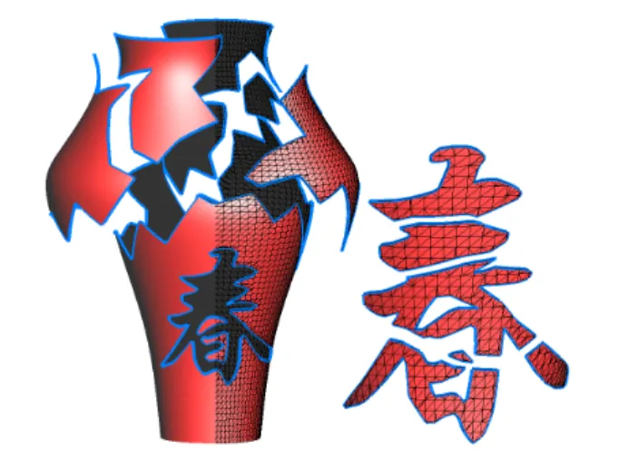
Figure 1. Mesh cutting. (The chinese charac-ter means The spring season)
more complicated mesh processing operations. Either auto-matic or semi-autoauto-matic, this operator needs to know where the mesh should be cut or trimmed. This information should be passed to the operator as a "cut-graph" which stores the embedding of cutting curves and the topology of the curves. To obtain a complex cut-graph, one should be allowed to sketch this cut-graph with iterations of drawing and eras-ing. The cut-graph can be seen as a planar map[1][9] em-bedded in a meshed surface. Similarly, the sketching of the cut-graph on meshes can be seen as "map sketching"[1][9] on a 3D mesh. The map sketching paradigm has been pro-posed to facilitate convenient interactive graphics design on 2D. We propose data structure and algorithms to facilitate sketching the cut-graph on meshed surface so as to extend this paradigm from 2D graphics design to 3D mesh edit-ing.
To design a cutting curve, the most straightforward and convenient way may be to design it along the edges of the mesh, which means that vertices of the graph correspond to the vertices of the surface. However, this yields jaggy bor-ders of the cut mesh. The cutting result is especially un-pleasant if the original mesh is irregular and coarse (the
black path shown in Figure 2-C). Despite the low complex-ity of this approach, it is not preferred. Therefore, in order to obtain smooth cut borders, one needs an embedding which allows to design a cutting curve whose vertices do not nec-essarily correspond to the vertices of the mesh.
Moreover, in order to enable to sketch a cut-graph more complex than a simple curve (see Figure 5), one needs incremental insertion of new cutting curves, i.e. with ev-ery cutting curve designed, new intersections between this new curve and the exiting cut-graph should be dynamically found and updated in the cut-graph. Then, through iterations of design and erasing, one obtains the desired cut graph. Sketching a cut-graph on a non-planar mesh is complicated since it requires a representation of the way the curve is em-bedded on the mesh. Moreover, from an interaction point of view, designing curves on a mesh is non-trivial.
1.1. Motivation
Though many studies have been done to do mesh cutting[3], few studies address the problem of find-ing a good topological data structure which facilitates both the embedding of curves and the sketching of a cut-graph on the mesh.
Our goal is to facilitate mesh cutting by providing a framework to sketch the cut-graph on meshes. The frame-work consists of two main parts as follows:
• Topological data structure and algorithms: provide
a robust and efficient embedding of cutting curves on the mesh and allow sketching by computing the cut-graph incrementally (this part will be detailed in Sec-tion 3),
• Interactive curve design tools: provide efficient and
convenient ways, which require the least intervention of the users, to design cutting curves. Thanks to the incremental computation of the cut-graph, one can sketch the cut-graph by mixedly using different curve design tools (this part will be detailed in Section 4).
2. Previous Work
2.1. Curve design on mesh
Kanai and Suzuki[13] design curves on meshed surface by linking two consecutive vertices of the curve by their shortest path (which will be introduced in Section 2.2) over the mesh. This is equivalent to linking two points in 2D by a straight line. Their shortest path algorithm does not find an exact solution. Hofer and Pottmann[12] proposed a spline-based method which gives more freedom to fit a curve to user-selected vertices by controlling the tension of the curve by a parameter w. Increasing w draws the resulting curve to the curve composed by the shortest path segments
A B C
Figure 2. The two green points are curve ver-tices. The red curves are the shortest path between the two vertices in each of the three figures. The black curve is also a geodesic in A, is a straight line in B, is the Dijkstra’s shortest path in C respectively.
(whose tension is maximum). The introduction of tension gives smoother curves by interpolating all the curve vertices and reduces the number of curve vertices.
In our work, we adapted a method to design curves sim-ilar to the one of Kanai and Suzuki[13]. We did not adapt the spline-based method for the sake of brievity ( However, this can be easily adapted to our structure).
2.2. Geodesic and shortest path problem
A geodesic is a locally length-minimizing curve. In the plane, the geodesics are straight lines. On the sphere, the geodesics are arcs of the great circles. Here, we are only in-terested in finding a geodesic between two points on a trian-gulated mesh. Hofer and Pottmann[12] proposed a method which finds the geodesic between points using energy-minimized splines on a triangulated mesh.
Sometimes, one needs not only a geodesic between two points but also needs it to be the shortest geodesic (which will be called shortest path henceforth, see Figure 2-A)), for instance, to do texture synthesis on surface[27].
Many algorithms are proposed to do so which can be cat-egorized into exact methods and approximate methods.
Exact solution: Mitchel et al.[24] and Kapoor[15] used
wavefront propagation method to compute shortest path with a complexity of O(n2logn) and O(nlog2n) respectively,
where n is the number of vertices. These methods fall into the Dijkstra paradigm; Chen and Han[5] proposed non-Dijkstra method which finds shortest path on a polyhedral surface convex or non-convex, with or without border. This algorithm works by unfolding the facets of the mesh. Al-though it has a O(n2) complexity, it is considered to be the only feasible exact method due to its simple concept.
Approximate methods: Kanai and Suzuki[13] proposed
an algorithm that computes the shortest path of a discrete weighted graph simplified from the original mesh. Then, this path is refined within a certain neighbourhood. The
shortest path found depends a lot on the first approximated path; Kimmel and Sethian[17] proposed a method which runs in O(nlogn). However, it can be quite inaccurate even in planar surface. Kirsanov et al.[18] proposed an approx-imate method which runs also in the same time complex-ity as Kimmel and Sethian[17] but guarantees exact solu-tion on a planar mesh.
Alternative The exact methods are generally
computa-tionally expensive. This prevents them from being used in interactive applications especially when the meshed model is large. The approximate methods, in spite of the improved computational time, do not always compute a satisfactory accurate solution. Therefore, we introduce a heuristic that uses exact methods and significantly reduces the computa-tional time by confining the search region for the shortest path to a subset of triangles. This heuristic will be detailed in Section 4.2.1.
3. Data Structure and Algorithms
This section introduces our data structure that rep-resents a cut-graph embedded in a polygonal surface. We identify several classes of cut-graph/surface rela-tions, and present algorithms for enforcing one-to-one cor-respondence from a weakly embedded graph. We show then how to use this algorithm to port the map sketch-ing paradigm[1][9] to meshed surfaces, and incrementally construct the cut-graph.
3.1. Definitions
Abstract cellular complex This section gives the classic
definitions and notations for abstract cellular complexes. The reader is referred to [22] for more details.
• let Γ be a finite set.
The elements of Γ are called the cells of Γ;
• let ≤ be a stricly partial order on Γ, i.e. a reflexive,
anti-symmetric and transitive relation.
The relation ≤ is referred to as the bounding relation;
• consider the function dim : γ → N characterized by: ∀γ, γ0∈ Γ × Γ, γ ≤ γ0and γ 6= γ0⇒
dim(γ) < dim(γ0)
The function dim is called the order function. A cell γ such that dim(γ) = k is called a k-cell, and k is called the dimension of γ;
• the function dim yields a partition of Γ into Γ0. . . Γn
defined by: ∀γ ∈ Γk, dim(γ) = k.
The maximum dimension n is called the dimension of the cellular complex Γ.
• the boundary B(γ) of a cell γ is defined by: B(γ) = {γ0∈ Γ|γ0 6= γ and γ0≤ γ}
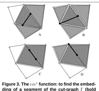
A B
C D
Figure 3. Theem∗function: to find the embed-ding of a segment of the cut-graph Γ (bold segment), we first find in which cells its ver-tices are embedded, and compute the inter-section of the stars of those cells (dashed zones).
• the star γ∗of a cell γ is defined by:
γ∗= {γ0 ∈ Γ|γ ≤ γ0}
• a geometric realization of Γ is an isomorphism putting Γ in correspondence with a set of open sets Γ0. The or-der relation ≤ is translated to Γ0as follows:
γ1≤ γ2⇔ γ01∈ ∂γ20
where ∂γ20 denotes the border of γ20. The geometric
re-alization is said to be conform if the geometric cells of
Γ0are disjoint.
Line embedded in a surface To represent a cut-graph
em-bedded in a surface, we use two abstract cellular complexes and one relation connecting them:
• the cut-graph can be represented by a 1-dimensional
cellular complex Γ = (Γ0, Γ1, ≤);
• the surface can be represented by a 2-dimensional
cel-lular complex Σ = (Σ0, Σ1, Σ2, ≤);
• the cells of the cut-graph are connected with the cells
of the surface by an inclusion relation ⊆ defined on
Γ × Σ.
Note that if the geometric realization is conform, we have:
∀σ1, σ26= σ1∈ Σ × Σ, σ1∩ σ2= ∅
then, for all γ ∈ Γ, we have at most one σ ∈ Σ such that
γ ⊆ σ. As a consequence, it is natural to represent the
rela-tion ⊆ by the funcrela-tion em : Γ → Σ ∪ {∅}, defined by:
em(γ) = σ where γ ⊆ σ if σ exists
A B C D Figure 4. Classes of cut-graph/surface relations. A: weakly-embedded cut-graph; B: strongly-embedded cut-graph; C: realized cut-graph; D: cut surface
The function em will be referred to as the embedding function in what follows. We now suppose that the embed-ding function em is combinatorially represented at the ver-tices of Γ. From an implementation point of view, we sup-pose that each vertex of Γ has a pointer to a cell of Σ. For instance, if the cut-graph Γ was manually digitalized on the surface Σ, the system stores in each vertex of Γ which cell of Σ was picked. Our goal is now to answer the following questions:
1. from the definition of em over the vertices of Γ, how can we deduce the definition of em over all the other cells of Γ ? In other words, can we find in which cells of Σ the edges of Γ are embedded ?
2. what are the combinatorial conditions of valid-ity which make this extension of em possible ? 3. from an invalid configuration, how can we define an
al-gorithm that enforces these conditions ?
To answer these questions, we consider the function
em∗: Γ → P(Σ) defined by:
em∗(γ) =\{em(γ0)?|γ0∈ B(γ) ∩ Γ0}
Intuitively, em∗(γ) computes the embeddings of all the
vertices of γ, and intersects the stars of all those embed-dings. Trivially, from the definition of em∗, we have:
∀σ ∈ em∗(γ), γ ⊆ (σ ∪ B(σ))
Figure 3 shows what the em∗function looks like for cer-tain cases. The two vertices of the cut-graph (black dots) are embedded in cells of the surface. The stars of those two cells are displayed using two different hashing styles. The inter-section is shown using crossed hashes.
However, as can be seen in the examples shown in Fig-ure 3-B and C, em∗(γ) may contain too many cells. To
de-termine the prolongation ¯em(γ) of em, i.e. to find the cell
of Σ in which γ is embedded, we need to filter-out the cells
σ of em∗(γ) such that γ ⊆ B(σ). This can be easily done
by finding the cell of minimum dimension in em∗(γ):
¯
em(γ) = em(γ) if γ ∈ Γ0
¯
em(γ) = σ ∈ em∗(γ) such that
dim(σ) = min{dim(τ )|τ ∈ em∗(γ)}
if em∗(γ) 6= ∅,
¯
em(γ) = ∅ otherwise
In examples C and D in Figure 3, em∗(γ) contains
two facets and one segments. Selecting the cell of low-est dimension enables the segment to be retreived. Note that the so-defined ¯em(γ) is unique, else this would
con-tradict the conformity assumption (Σ would have two intersecting cells). This extension em of the em func-¯
tion answers question 1.
Now we want to answer question 2, e.g. identify the in-valid configurations. As shown in Figure 6-A, a segment γ of Γ cannot be embedded in a cell σ of Σ if its extrem-ities are embedded in two cells σ1 and σ2 that are "too
far away”, i.e. if we cannot find a cell σ in Σ such that
σ1, σ2 ∈ (B(σ) ∪ {σ}) 2
. This condition also corresponds to em∗(γ) = ∅.
The other invalid configuration occurs when the cut-graph Γ is non-conform (Figure 6-B). Note that if we got a non-conform cut-graph we have two seg-ments γ16= γ2and γ1∩ γ26= ∅. If ¯em is defined, we know
that the two segments are embedded in the same cell σ of Σ, i.e. ¯em(γ1) = em(γ¯ 2) = σ, and that the
intersec-tion γ1∩ γ2is embedded in σ. This will be used later to
A
B
C
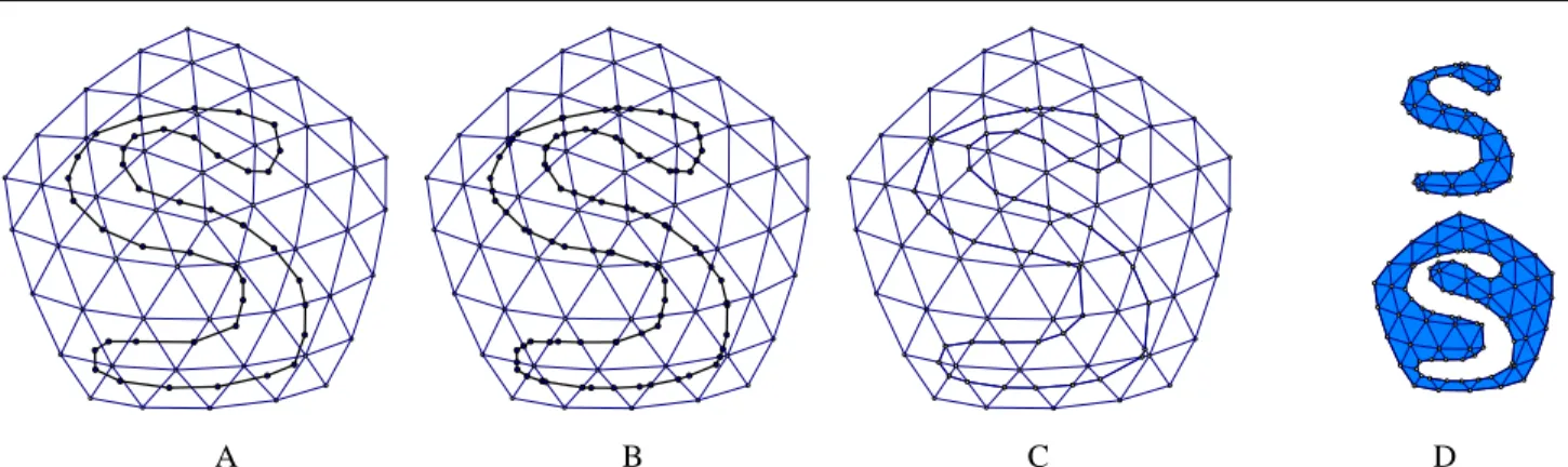
Figure 5. Sketching the cut-graph on meshes. A&B: dangling curve segments are erased in the sketch; C: An "art-nouveau"-style door(inspired by the image) 3D model is being designed.
The domain of definition of the embedding function ¯em
makes it possible to distinguish three different classes of cut-graph/surface relations. We say that the cut-graph is:
• weakly embedded (Figure 4-A) if the function ¯em is
defined at the vertices only;
• strongly embedded (Figure 4-B) if the function ¯em
is defined at the vertices and the segments, i.e. ∀γ ∈
Γ, ¯em(γ) 6= ∅;
• realized (Figure 4-C) if the cells of γ are
embed-ded in cells of the same dimension in Σ, i.e. ∀γ ∈
Γ, dim( ¯em(γ)) = dim(γ).
Using these notion, it is possible to answer question 3, by designing an algorithm that enforces the realized con-dition from a weakly embedded and possibly non-conform cut-graph:
A B
Figure 6. Invalid embedding configuration: A: emptyem∗; B: non-conform cut-graph.
1. ensure strong embedding
For all γ ∈ Γ1 such that ¯em(γ) = ∅, replace γ with
the geodesic traced on Σ that links the two extremities of γ
2. ensure conformity of cut-graph
•2.1 For all σ in Σ0, merge all the vertices of Γ
em-bedded in σ.
•2.2 For all σ in Σ1, sort the vertices of Γ embedded
in σ along σ.
•2.3 For all σ in Σ2, intersect all the edges of Γ
em-bedded in σ (using a line-sweeping algorithm). 3. realize the cut-graph in the surface
Insert all the missing vertices and edges in Σ.
Note that the algorithm uses as much combinatorial in-formation as possible: intersection computations are sys-tematically restricted to the smallest possible cell of Σ, by using the ¯em function. This improves both robustness and
efficiency as compared to a pure geometrical solution. All the intersections are either sorted along edges (1D) or within facets of Σ (2D). The only required geometric computations are the geodesic tracing algorithm (in step 1), sorting points along edges (in step 2.2) and segments intersections within facets (in step 2.3).
Figure 5 shows initially non-conform cut-graphs made conform by applying step 2 after each curve design.
Implementation details: From a practical point of view, each cell σ of Σ stores the list of cells
em−1(σ) = {γ| ¯em(γ) = σ} (in our
implementa-tion, each cell of Σ hasstd::vector of pointers). To represent the cut-graph Γ, our implementation uses a clas-sical graph data structure. The surface Σ is represented by a halfedge data structure (see e.g. [2][6][20][16][4]). We use our implementation[10], that has the possibility of dynam-ically attaching information to the cells of the represen-tation (the vertices of Γ store em and the cells of Σ store
¯ em−1)
Complexity: Let n = |Γ| denote the number of cells of the
cut-graph and m = |Σ| the number of cells of the surface. In our algorithm, the most costly step is the geodesic computation algorithm. The method we use (Chen and Han’s method) has O(m2) complexity. With the heuristic
we use, this reduces to O(mlog(m)) (at the expense of not always returning the shortest geodesic, which is not prob-lematic for our application).
Worst case complexity: For enforcing the strong
em-bedding condition, there are two degenerate configurations: if the cut-graph is completely embedded in a single facet, the algorithm reduces to constructing a planar map of the cut-graph, with a worst-case complexity of O(n2) (see
Fig-ure 7-A). If the surface has two vertices with a high valence and the cut-graph connects these two vertices, the bottle-neck is the stars intersection computation (intersection of two sets), which costs O(m log(m)) (see Figure 7-B).
Average complexity: In real-life cases, the cut-graph
and the surface have similar resolutions, which means that each facet contains at most one intersection of the cut-graph, and the complexity reduces to O(n). In practice, all the examples shown in this paper run in less than one sec-ond.
A B
Figure 7. Configurations of worst case com-plexity.
4. Interactive toolbox for curve design on
sur-face
To sketch the cut-graph, one needs to design curves on the surface. We present a toolbox for curve design which combines the vector and bitmap graphics paradigms. It al-lows sketching the cut-graph by mixedly using the tools. It has been inspired by some 2D graphics softwares which combine the two graphics paradigms to provide a con-venient graphics design environment. We extended this mixedly-use idea from 2D graphics design to 3D mesh edit-ing. However, this extension from 2D to 3D is not trivial since the data structure and algorithms presented in Section 3 which facilitate the embedding and incremental computa-tion of the cut-graph is required for sketching on meshes.
4.1. 2D drawing
In 2D, drawing tools fall in one of the following two paradigms,
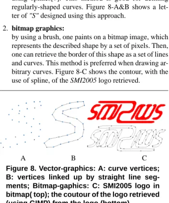
1. vector graphics:
the user defines a curve by specifying a sequence of points of this curve. There are two ways to inter-prete this sequence of point to obtain a curve. One can either connect consecutive points by straight lines (geodesics) or interpolate the points to form curves using splines[7]. This method is good for defining regularly-shaped curves. Figure 8-A&B shows a let-ter of "S" designed using this approach.
2. bitmap graphics:
by using a brush, one paints on a bitmap image, which represents the described shape by a set of pixels. Then, one can retrieve the border of this shape as a set of lines and curves. This method is preferred when drawing ar-bitrary curves. Figure 8-C shows the contour, with the use of spline, of the SMI2005 logo retrieved.
A B C
Figure 8. Vector-graphics: A: curve vertices; B: vertices linked up by straight line seg-ments; Bitmap-gaphics: C: SMI2005 logo in bitmap( top); the coutour of the logo retrieved (using GIMP) from the logo (bottom).
A B C D
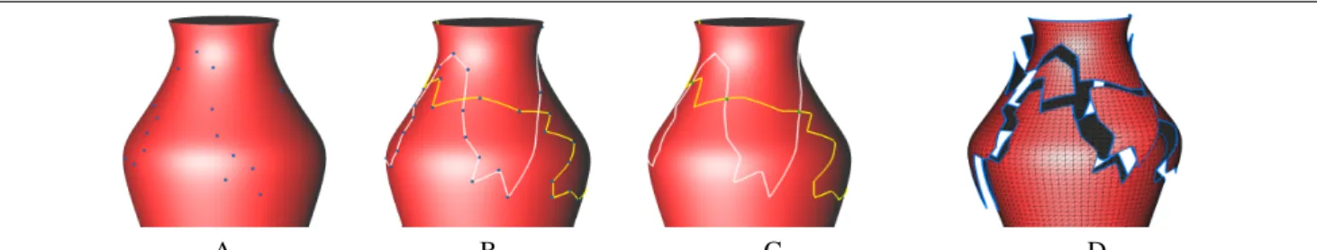
Figure 9. Cutting using the vector-graphics tool. A: Curve vertices(blue points) designed by user; B: consecutive points are linked by geodesics(white and yellow segments); C: cut-graph formed by several cutting curves with calculated intersections(green points); D: cut mesh
Nowadays, more and more 2D graphics softwares, for in-stances, Canvas, CorelDraw and Flash, provide unified de-signing environment. Designers benefit from tools from the both paradigms. This evolution in the 2D world inspired us to extend this idea from the 2D graphics to 3D mesh edit-ing.
4.2. The toolbox
This toolbox consists of tools from each of the two paradigms. One can mixedly use different tools to sketch the cut-graph on the mesh.
4.2.1. Vector-graphics tool: the user can design a curve
on the meshed surface S by defining a sequence of curve vertices vi∈S, i=1,...,n on the mesh surface. The curve
ver-tices are not necessarily verver-tices on the mesh. Unlike in 2D, the segment between two vertices on a curve on a mesh sur-face is no longer a straight line but a geodesic (as shown in Figure 2-B). Consecutive points are linked by a segment calculated by our geodesic algorithm which will be detailed below. An example of the application of this tool is demon-strated in Figure 9.
Since our goal is to facilitate interactive mesh editing, we could not afford to use exact shortest path methods with quadratic complexity or even worse, especially for large meshed models. Though approximate methods find non-exact shortest path in a reasonable time, non-exact solution is always preferred. On the other hand, exact methods execute in reasonable time provided that the number of vertices is small enough even with their quadratic complexity.
Our heuristic works as follows: Provided that the start-ing and destination points on the mesh are not too far away one from each other, we can find an exact shortest path be-tween these two points by restricting the search in a small local region. The method consists of two steps, we first find the Dijkstra’s shortest path, i.e. the shortest path along the edges of the mesh (as shown by the black curve in Figure 2-C), between these two points. Then, with this path, we find a ribbon-like neighbourhood (as shown by the orange
re-gion in Figure 2-C) along this path. Within this neighbour-hood, we apply an exact method to find the shortest path be-tween these two points. We use the implementation of the Chen and Han[5] provided by Kaneva and O’Rourke[14]. In this way, by limiting the number of vertices to the num-ber of vertices in this band of neighbourhood, our method reduces the computation time enough to be used for inter-active mesh editing operations even on large meshed mod-els.
4.2.2. bitmap-graphics tool: Through a 3D painting
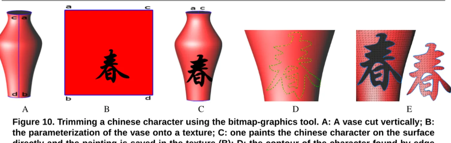
sys-tem (as demonstrated in Figure 10), which requires a param-eterization [8] (mapping from 3D to 2D), users can paint di-rectly on the meshed surface to obtain a desired form. Note that the parameterization does not need to be global (a local parameterization is sufficient). Only the interested region is parametrized to a single chart. Thanks to the parameteriza-tion, the painting is stored in a texture. After the painting is finished, the sharp edges on this image are detected and re-treived as a set of 2D curves. Again through the parameteri-zation, these 2D curves are mapped back to a 3D cut-graph. Figure 10 demonstrates the results of trimming the chinese character using the bitmap-graphics tool.
4.2.3. Mixedly use of the tools: One can mixedly use the
two tools introduced above to sketch a cut-graph. Figure 11 shows an example of sketching the cut-graph by using both the bitmap-graphics tool and the vector-graphic tool.
5. Conclusion
With the goal to facilitate interative mesh editing, a framework to sketch a cut-graph on a mesh for cutting is presented. This can be thought of as a generalization of 2D map sketching[1][9] to 3D meshed models. Using the proposed data structure, smooth cutting curves can be de-fined. Moreover, with the topological nature of the data structure, the desired cut-graph can be sketched after iter-ations of designing and erasing. During these iteriter-ations, the curve designing tools from both vector and bitmap-graphics paradigms can be used. Sketching the cut-graph on a mesh
A B C D E Figure 10. Trimming a chinese character using the bitmap-graphics tool. A: A vase cut vertically; B: the parameterization of the vase onto a texture; C: one paints the chinese character on the surface directly and the painting is saved in the texture (B); D: the contour of the character found by edge detection on the texture is mapped back to 3D as a cut-graph; E: trimming result with the character.
is particularly useful for shape modeling (see Figure 1, 9 and 10) and architectural (see Figure 5-C) applications.
In addition to be used manually by designers, the sketch-ing concept may be applied to some automatic operations, for instance, given a cut-graph output from an algorithm of a mesh segmentation method, the jaggy borders between charts can be easily replaced by the geodesic paths (as shown in Figure 12) to give a texture atlas with smooth chart borders. This improves both texture mapping (by reducing boundary artifacts) and spline-fitting processe).
With the robustness and efficiency of the data structure and algorithms, the mesh cutting operation presented can serve the very important "infrastructural-block" role in a mesh editor.
6. Future Works
In future work, we will explore possible integration of other cut-graph design tools, such as splines as in [12], and
A B
Figure 11. Sketching the cut-graph by mixedly using the tools. A: the blue and green curves are designed using the bitmap and vector-graphics tool respectively; B: note that some dangling curve segments are erased.
templates, as in intelligent scissoring [19].
Another research topics concerns the generalization to objects of higher dimensions. The data structure we have defined, and the way to extend the em function is indepen-dent on the dimension. As a consequence, it is possible to use our approach to cut meshed volumes by surfaces.
In our approach, the cut-graph can self-intersect, and the intersections are efficiently retreived. However, a limitation of our approach is that it requires a conform surface, i.e. the surface cannot self-intersect. Overcoming this limitation re-quires more complex data structures, since the embedding relation is not injective anymore. Designing a combinato-rial data structure for non-conform configurations is another possible direction of research that we will explore. The re-sult will facilitate the design of CSG operators for meshed shells.
7. Acknowledgement:
Many Thanks to Fabien Boutantin for the vase demo and generating the "art nouveau" model; Wei-Ming Dong for the chinese character in the vase demo.
References
[1] P. Baudelaire and M. Gangnet. Planar maps: An interaction paradigm for graphic design. In Proc. of CHI-89, pages 313– 318, Austin, TX, 1989.
[2] B. Baumgart. A Polyhedron Representation for Computer Vision. In AFIPS Nat. Conf. Proc., volume 44, pages 589– 596, June 1975.
[3] C. Bruyns, S. Senger, A. Menon, K. Montgomery, S. Wil-dermuth, and R. Boyle. A survey of interactive mesh-cutting techniques and a new method for implementing generalized interactive mesh cutting using virtual tools. Journal of
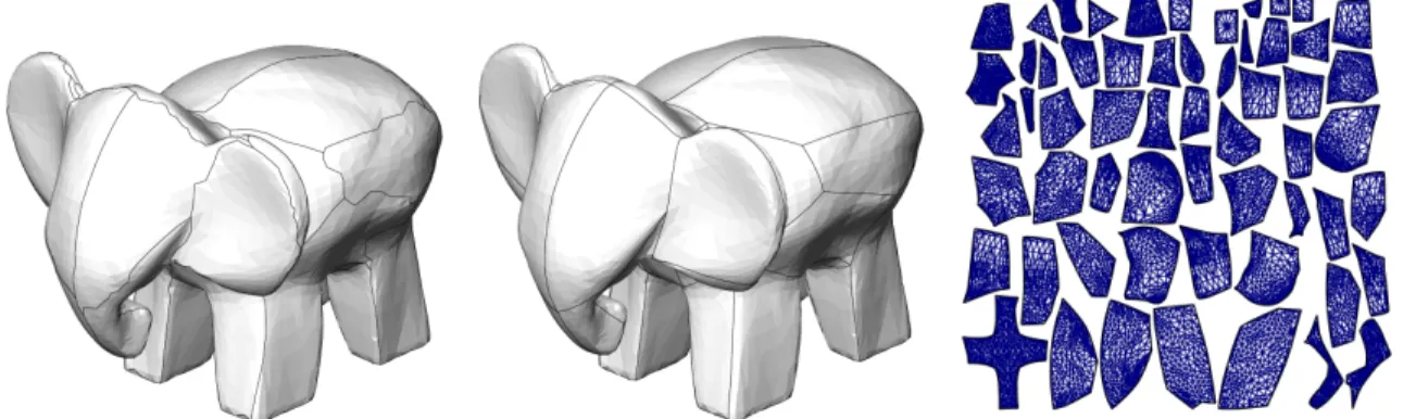
Figure 12. Creating a texture atlas with smooth boundaries. This improves both texture-mapping methods and spline reconstruction. Left: texture atlas with jaggy boundaries; center: texture atlas with geodesics; right: parameter space
[4] CGAL. Computational Geometry Algorithms Library. In
http://www.cs.ruu.nl/CGAL/index.html.
[5] J. Chen and Y. Han. Shortest paths on a polyhedron. In Sixth
ACM Symposium on Computational Geometry, 1990.
[6] J. Edmonds. A Combinatorial Representation for Polyhedral Surfaces. Notices Amer. Math. Soc., 7, 1960.
[7] G. Farin. Curves & Surfaces for CAGD: A Practical Guide. Morgan Kaufmann, 2002.
[8] M. S. Floater and K. Hormann. Surface parameterization: a tutorial and survey. In N. A. Dodgson, M. S. Floater, and M. A. Sabin, editors, Advances in Multiresolution for
Geometric Modelling, Mathematics and Visualization, pages
157–186. Springer, Berlin, Heidelberg, 2005.
[9] M. Gangnet, J.-C. Hervé, T. Pudet, and J.-M. V. Thong. In-cremental computation of planar maps. Computer Graphics, 23(3):345–354, 1989.
[10] Graphite. In http://www.loria.fr/∼levy/Graphite/index.html, 2003.
[11] X. Gu, S. Gortler, and H. Hoppe. Geometry images. ACM
SIGGRAPH, pages 355–361, 2002.
[12] M. Hofer and H. Pottmann. Energy-minimizing splines in manifolds. ACM SIGGRAPH, pages 284 – 293, 2004. [13] T. Kanai and H. Suzuki. Approximate shortest path on a
polyhederal surface and its application. In Computer-Aided
Design, vol. 33, pages 801–811, 2001.
[14] B. Kaneva and J. O’Rourke. An implementation of chen and han’s shortest paths algorithm. 12th Canadian Conference
on Computational Geometry, 2000.
[15] S. Kapoor. Efficient computation of geodesic shortest paths. In 32nd Annual ACM Symposium on Theory of Computing, 1999.
[16] L. Kettner. Designing a data structure for polyhedral sur-faces. In Proc 14th Annu. ACM Sympos. Comput. Geom., pages 146–154, 1998.
[17] R. Kimmel and J. Sethian. Fast marching methods on trian-gulated domains. Proc. National Academy of Sciences, pages 8341–8435, 1998.
[18] D. Kirsanov, S. Gortler, and H. Hoppe. Fast exact and ap-proximate geodesic paths on meshes. In Harvard University
Computer Science TR 10-04, 2004.
[19] Y. Lee, S. Lee, and A. Shamir. Intelligent mesh scissoring using 3d snakes. Pacific Graphics 04, 2004.
[20] P. Lienhardt. N-Dimensional Generalized Combinatorial Maps and Cellular Quasi-Manifolds. Journal on
Computa-tional Geometry and Applications, 4(3):275–324, 1994.
[21] B. Lévy, S. Petitjean, N. Ray, and J. Maillot. Least squares conformal maps for automatic texture atlas generation. In
Proceedings of the 29th annual conference on Computer graphics and interactive techniques, pages 362–371. ACM
Press, 2002.
[22] W. Massey. A Basic Course in Algebraic Topology. Springer Verlag, 1991.
[23] J. Mitani and H. Suzuki. Making papercraft toys from meshes using strip-based approximate unfolding. ACM
SIG-GRAPH, 2004.
[24] J. Mitchell, D. Mount, and C. Paradimitriou. The discrete geodesic problem. In SIAM J. Computing, 1987.
[25] M. Mortara, G. Patane, M. Spagnuolo, B. Falcidieno, and J. Rossignac. Blowing bubbles for the multiscale analysis and decomposition of triangle-meshes. Algorithmica vol 38
no.1, 2004.
[26] M. Mortara, G. Patane, M. Spagnuolo, B. Falcidieno, and J. Rossignac. Plumber: A method for a multi-scale decompo-sition of 3d shapes into tubular primitives and bodies. ACM
Symposium on Solid Modeling, 2004.
[27] F. Neyret and M. P. Cani. Pattern-based texturing revisited.