HAL Id: cea-02439458
https://hal-cea.archives-ouvertes.fr/cea-02439458
Submitted on 26 Feb 2020HAL is a multi-disciplinary open access archive for the deposit and dissemination of sci-entific research documents, whether they are pub-lished or not. The documents may come from teaching and research institutions in France or abroad, or from public or private research centers.
L’archive ouverte pluridisciplinaire HAL, est destinée au dépôt et à la diffusion de documents scientifiques de niveau recherche, publiés ou non, émanant des établissements d’enseignement et de recherche français ou étrangers, des laboratoires publics ou privés.
Numerical simulation of HELICOFLEX metallic gasket
ageing mechanism for spent fuel
F. Ledrappier, J. Juliaa, A. Beziat, K. Vulliez, L. Mirabel, M. Wataru, K.
Shirai, H.-P. Winkler, R. Hueggenberg
To cite this version:
F. Ledrappier, J. Juliaa, A. Beziat, K. Vulliez, L. Mirabel, et al.. Numerical simulation of HELI-COFLEX metallic gasket ageing mechanism for spent fuel. PATRAM 2016 - The 18th International Symposium on the Packaging and Transportation of Radioactive Materials, Sep 2016, Kobe, Japan. �cea-02439458�
Proceedings of the 18th International Symposium on the Packaging and Transportation of Radioactive Materials PATRAM 2016
September 18-23, 2016, Kobe, Japan
1
Numerical simulation of HELICOFLEX®
metallic gasket ageing mechanism for spent fuel
F. LEDRAPPIER ; J.F. JULIAA
TECHNETICS Group France Laboratoire d’Etanchéité, 2 rue James
Watt, F-26700 Pierrelatte, France
A. BÉZIAT ; K. VULLIEZ ; L. MIRABEL
CEA, DEN, SDTC, Laboratoire d’Etanchéité F-30207 Bagnols Sur Cèze, France
M.WATARU ; K.SHIRAI
Central Research Institute of Electric Power Industry - 1646 Abiko, Abiko-shi,
Chiba-ken 270-1194 Japan
H-P.Winkler ; R.Hueggenberg
Gesellschaft für Nuclear-Service GmbH, Frohnhauser Strasse 67, 45127 Essen,
Germany
Abstract
In the framework of CEA, GNS and CRIEPI collaboration an experimental program is being carried out, in the CEA Marcoule - TECHNETICS GROUP France joint lab, to assess the long-term use of HELICOFLEX® metallic seals in spent nuclear fuel storage casks.
Beside an experimental program of 100,000 hours accelerated ageing at different temperatures, a numerical model using finite element analysis has been developed to study seal ageing mechanisms and help the extrapolation of these behaviour to various ageing conditions and seal designs.
The studies rely on use of the Larson-Miller parameter to define a time-temperature equivalence that has the advantages to be relevant to describe ageing mechanisms and to be easy to use to study different ageing scenarios. However, this analytical approach faces challenges when seal designs and materials change. Thus, to ensure the model reliability, any seal design change should require additional long term and expensive ageing tests.
The presentation presents the latest developments related to HELICOFLEX® seals numerical simulation. Indeed, to help the seals behaviour extrapolation for different seal designs, mechanical tests and a specific 3D detailed numerical model has been developed to describe its relaxation mechanisms. This model details the different stages of live of the seal with compression, thermal transient and ageing itself and could be used to assess the evolution of the residual spring-back. The relevance of this simulation is assessed and discussed regarding the available database related to long term ageing tests at different temperatures.
Introduction
Long-term dry storage of spent fuels in metal casks is a very commonly used solution. This technical choice requires the use of leak-tight casks and therefore seals to ensure a containment criterion [1]. Among a large panel of existing sealing systems, the expected lifetime of the casks, that can exceed
one hundred years, combined with thermal constraints favor the use of metallic seal based technologies [2].The optimal seal arrangement to efficiently ensure the long-term tightness between the cask closure flanges relies on a Metal To Metal (MTM) contact between them [3][4], a mechanical junction where the gasket load relaxation is one of the key parameters regarding sealing performances over time [5].
To investigate the detrimental loss of leak-tightness linked to the time-evolution of the seal materials, a long-term ageing experimental campaign has been conducted on a large panel of mockups that consist in two symmetric bolted flanges holding a tightened HELICOFEX® seal. These ageing tests provide a large database of more than 450 points, for different ageing temperature (RT, 100 °C and 200 °C) and for ageing time up to 100,000 hours. The harvested results have been interpreted using the Larson & Miller Parameter (LMP) for time-temperature equivalence [6][7][8]. Even if this approach remains relevant to assess seals behavior at a given ageing time and temperature, these results are only applicable for the tested seal designs. Any extrapolation of these results to other casks design would be risky, and so additional long term ageing tests are required.
Therefore, a numerical model of seals ageing behavior using Finite Element Analysis (FEA) has been developed to assess ageing mechanisms of different seals design, in different ageing scenario. The available experimental database is then a reliable support for numerical model validation.
EXPERIMENTAL DATABASE
HELICOFLEX® seals characteristics
The HELICOFLEX® is a metallic seal (Fig.1) patented and manufactured by TECHNETICS Group. It consists in a helicoidal spring covered by linings. With a proper combination of materials for spring and linings, this structure provides high sealing performances with leakage-rate below 10-10 Pa.m3.s-1, tolerant to flanges surfaces imperfections (roughness, waviness), with a significant spring back able to keep the leak-tightness with severe thermal transient, pressure effect or external loads. The HELICOFLEX® is therefore well suited for long-term use in nuclear spent fuel casks.
Figure 1: HELICOFLEX® metallic seals
The seals mechanical behavior can be described by the set of parameters summarized in Table 1 and Fig.2. Among them, the program detailed in this paper focus on the evolution of the residual linear load and total spring back (Y2R and rtR) remaining on the seal after tightening followed by different
Outer lining
Inner lining Spring
ageing scenario.
Figure 2: HELICOFLEX® seals characteristic curve Table 1:Parameters definitions
Symbol Units Definition
Y2 (N/mm) Linear load of a seal after tightening at room temperature.
Y2R (N/mm) Residual linear load at nominal compression e2 after ageing.
Y0 (N/mm)
Linear load of seal required to obtain the leak-tightness during the first seal tightening.
Y1 (N/mm)
Linear load below which the leak rate exceeds a target value, upon decompression of a seal in standard conditions (RT, ∆P = 1bar)
Y1R (N/mm)
Linear load below which the leak rate exceeds a target value, upon decompression of a seal, after ageing
e2 (mm) Nominal compression of a seal
rt, rtR (mm) Total spring back of a seal respectively before and after ageing
ru, ruR (mm)
Useful spring back of a seal (no leak occur), respectively before and after ageing
ageing
Post-ageing decompression
Two seals designs have been subjected to long terms (i.e. up to 100,000 hours) ageing tests, with two different cross-sectional diameters: 6.2 mm and 8.4 mm. Both seals design have a spring made of Nimonic 90 alloy, an inner lining made of 304L stainless steel, and a silver outer lining. The nominal compressions (e2) are 1.1 and 0.9 mm, and the corresponding initial maximum linear loads (Y2) are
410 and 545 N/mm respectively.
For the study the seal mean-diameter is 250 mm, to be compared with the real application diameters ranging from 1 to 2 meters.
Ageing tests procedure
As the ageing tests are carried out for over 10 years, test procedure has been described in other publications [6][7]. The seal is installed in a groove between two rigid blinded flanges. The initial tightening is obtained with a hydraulic instrumented press to achieve the MTM contact. During the process the load F and the seal compression ∆e are measured (Fig.3). The Y2 and the corresponding
seal compression e2 are determined when the MTM is obtained. The bolts of the mockup, kept under
the press, are then screwed up to a given torque. Once released from the press, mockups are piled up inside an oven maintained at a constant temperature. In this program about 40 mockups are used for each of the three selected temperatures: RT, 100°C and 200°C.
Figure 3: Test principle: Left side – mockup under the press. Right side – mockups piled up inside a furnace
After a given ageing period, the mockups are removed from the oven and once at RT placed back under the instrumented press. Then, they are loaded up to the Y2 load before removing bolts. The
load applied by the press is then decreased down to an opening of the flanges of 50 µm, while the load and the distance between the flanges are measured to obtain the unloading curve.
These tests reveal an Y2R drop (see Fig. 6) that increases with ageing time and temperature, which
could be expressed using the Larson & Miller Parameter, as follow:
LMP(T; t) = T ∙ [C + log10(t)] (Eq. 1)
T is the ageing temperature (K) t is the ageing time (hours)
This residual linear load drop results from the outer liner creep mechanisms, which leads to its thinning and so to release of the spring, which then works along its unloading curve. Thus, this ageing mechanism depends on silver strain rates under spring load and spring unloading curve. The use of numerical simulation aims to assess these two mechanisms of seals ageing to help the extrapolation of these results to other seal designs and ageing scenario.
NUMERICAL MODEL PRESENTATION
Geometry and materials behavior
A numerical model has been developed to analyze tests results and extrapolate these data to real ageing conditions. The HELICOFLEX® seals behavior has been studied with ABAQUS® v2016 software. The following figure presents the model and the mesh considered for this simulation.
Figure 4: Mesh considered for HELICOFLEX® seals simulation
Beside 2D-axisymetric models used in the past [7], which consists in replacing the spring by an equivalent pipe, this 3D simulation of seals segment improve drastically the description of seals spring-back, which is an issue for casks transportation after ageing.
This model considers a sample of 5 coils to describe the spring behavior. A coupling condition between the two opposite faces is implemented to describe the periodic symmetry condition of this component.
Symmetry planes (R-Z planes in the cylindrical coordinate system associated to the seal) are defined along both sides of liners.
Flanges are considered as perfectly rigid bodies and are driven with the help of reference points to determine the required load to reach a given compression. Interactions between respective bodies are sliding contacts described with a Coulomb’s friction law. A friction coefficient of 0.15 is considered.
For compression and ageing simulation, a specific elastic-plastic behavior is considered for each component of the seal (spring, inner lining and outer lining) with the help of tabulated data, including temperature dependence. In addition, visco-plastic behavior is considered for Silver outer lining for ageing simulation. It has been implemented as a strain-hardening creep model which describes the strain-rate as a function of the stress and strain as follow:
𝜀𝜀̇ = {𝐴𝐴 ∙ 𝜎𝜎𝑛𝑛∙ [(𝑚𝑚 + 1) ∙ 𝜀𝜀]𝑚𝑚}1�𝑚𝑚+1 (Eq. 2)
ε is the strain, 𝜀𝜀̇ is the strain rate (s-1)
σ is the stress (MPa)
A, n, m are material constants. The A coefficient varies with the temperature.
The simulation precision relies not only on the geometry and simulation techniques, but also on the relevance of materials behavior model implemented in the model for that analysis. For that purpose specific creep-tests have been performed to determine coefficients of the model introduced above.
Simulation methodology
3D simulation of HELICOFLEX® seals behavior meet different convergence issues related to severe non-linearities, especially related to contact initiation and evolution between different seals component (spring coils / inner lining, inner lining/outer lining, outer lining/flange). To bypass such issues, an explicit solver is used for seal compression simulations. The relevance of this approach could be assessed with a comparison of the experimental and calculated characteristic curves. It highlights a good correlation between numerical results and measurement: calculated linear load and spring back are 551 N/mm and 0.212 mm, while measured values are 549 N/mm and 0.205 mm respectively.
However, explicit simulation is on principle not compatible with long term behavior like creep. This point is addressed by importing the deformed mesh and the corresponding fields into a second model for an implicit simulation of ageing, and spring-back. Thus, for different seal designs, the second analysis related to ageing simulation is divided as follow:
• Initial state: Importing results of compression simulation.
• Step 1: Stabilization. No change occurs on loads and displacement. It only aims to provide a stabilization of stress fields and contacts following dynamic solution of compression.
• Step 2: An implicit coupled temperature-displacement analysis consists in increasing the temperature linearly up to the testing temperature (i.e. 100°C or 200°C). Thermal transient is supposed to be slow enough to consider temperature fields as homogenous all over the seal. It leads to a thermal expansion of seals components and a modification of mechanical behavior. • Step 3: Visco-plastic analysis (time influence). 100,000 hours ageing (3.6 x 10⁸ s) at the test
temperature.
• Step 4: Implicit temperature-displacement analysis ; Temperature decreases down to 20 °C • Step 5: Implicit analysis ; Unloading at 20 °C
The only ageing mechanism considered is related to the creep of the outer jacket, made of 99.99% pure silver, at ageing temperature. It leads to a thinning of the liner, due to the compressive stress related to the pinching between spring and flanges. The result is a significant unloading of the spring itself, at a constant compression of the seal.
SIMULATION RESULTS
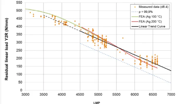
The following figure compares ageing tests results (scatter plot) with simulations results (green and red continuous lines for ageing at 100°C and 200°C respectively). This figure highlights the relevance of numerical simulation, with a calculated Y2R drop curve passing through the experimental scatter plot.
Figure 6: Y2R drop vs. Larson Miller Parameter - Comparison of measured and calculated values
In this figure, contrary to analytical processing considered otherwise [6][7]:
• Tests results related to 100,000 hours ageing tests at room temperature are considered in the study (LMP ~4000 in figure hereafter). These data have been excluded in previous analytical approaches [6].
• The simulation highlight an inflexion point in Y2R vs. LMP curve, related to seals relaxation mechanisms: the residual linear load drop rate decreases as load applied on seals decreases. • The C parameter related to the LMP has been adjusted to C = 9 for ∅8.4 mm seals.
Considering C = 11 leads to a 30 N/mm gap between 100 °C and 200 °C ageing simulation. Adjustment of this value allows observing a continuity of the trend curve related to different ageing temperature. This continuity strengthens the relevance of the LMP as time-temperature equivalence for seals behavior forecast.
forecasted residual linear load, regarding previous works conclusions: changing C from 11 to 9 leads to a 64 °C increase of the maximum ageing temperature to keep residual linear load above a threshold for 99.9% of seals after 60 years ageing.
Besides its ability to predict evolution of residual linear load due to ageing, the numerical simulation is also relevant to assess residual spring back evolution. The following Figure 7 compares the calculated spring back after 100,000 hours at 100 °C (in bold) to a sample of 11 measurements (thin lines).
Figure 7: Spring back analysis – After 100,000 h @ 100 °C
This analysis reveals a 1/100 mm gap between simulations and measurements, which is of the order of measurements scatter.
CONCLUSIONS
The results detailed above reveals that, the 3D numerical model developed to study HELICOFLEX® seals behavior is relevant not only to analyze characteristic curves (loading/unloading), but also to consider their ageing mechanisms. Besides improvements in simulation techniques, the silver creep model considered is also a key point for the precision of the ageing numerical simulations.
Following a characterization of silver creep behavior, the numerical analysis, validated by a significant experimental database of ageing tests up to 100,000 hours at different temperatures (RT, 100 °C and 200 °C), makes possible the forecast of seals residual linear load and total spring back, in different ageing scenario. Furthermore, the advantage of numerical analysis is its ability to be generalized to consider behavior of other seals design. Thanks to the numerical model, the ageing tests at room temperature were exploited describing realistically slope change related to relaxation mechanisms. These two points were neglected in previous linear simplified models of seals ageing.
It is interesting to note that numerical simulations consider only nominal dimensions and mechanical behavior of each seal components. Seals behavior scattering is not considered in this approach and could be a relevant complement to this program.
Moreover, one can notice that seals behavior forecast rely on material model relevance. If this approach has been evaluated for the accelerated ageing tests, its relevance or conservatism for different ageing scenario (i.e. lower temperature and longer ageing time) should be considered and justified.
Acknowledgments
These works were performed in the joint research program among CEA, GNS and CRIEPI, in the CEA Marcoule - TECHNETICS GROUP France joint lab.
References
[1] Yamamoto, T., 2001. Dual-purpose metal cask integrity after long-term interim storage (activities for the verification
test of a dual-purpose metal cask). In: Proceedings of the PATRAM 2001, Chicago, IL, USA, September 7–9.
[2] Droste, B., 1988. Safety evaluation of dry spent fuel storage casks. In: Soviet-West German Seminar, USSR, Leningrad, June 27–July 1.
Benda, B.J., Langland, R.T., 1980. Methods for Evaluating the Leak Tightness of Spent Fuel Container Closures. Lawrence Livermore Lab.
[3] Rouaud, C., Lefrancois, M., Caplain, P., 1999. Static sealing: technologies of the future. In: Proceedings of the First International Conference on Sealing Technology and Plant Leakage Reduction, Charlotte, NC, USA, November 15–19. [4] Birembaut, Y., Ledauphin, T., Vignaud, J.C., 2001. Mechanical and sealing performances of gaskets specifically
manufactured for use in metal to metal conditions. In: PVP Conference 2001.
[5] Benda, B.J., Langland, R.T., 1980. Methods for Evaluating the Leak Tightness of Spent Fuel Container Closures. Lawrence Livermore Lab.
[6] H. Sassoulas , L. Morice , P. Caplain, C. Rouaud, L. Mirabel , F. Beal, Ageing of metallic gaskets for spent fuel casks:
Century-long life forecast from 25,000-h-long experiments. In Nuclear Engineering and Design 236 (2006), p 2411-2417.
[7] A.Béziat, F.Ledrappier, K.Vulliez, B.Deschamps, J.F.Juliaa, L.Mirabel, M.Wataru, K.Shirai, H-P.Winkler Ageing of
Helicoflex® metallic gasket for spent fuel cask: results and analysis of sealing performances of a 75,000h campaign
Proceedings of the 17th International Symposium on the PATRAM 2013 - San Francisco, CA, USA
[8] Larson, F.R., Miller, J., 1954. A time–temperature relationship for rupture and creep stresses. Trans. ASME 174, 765–775.