HAL Id: hal-02357414
https://hal.archives-ouvertes.fr/hal-02357414
Submitted on 17 May 2021HAL is a multi-disciplinary open access
archive for the deposit and dissemination of sci-entific research documents, whether they are pub-lished or not. The documents may come from teaching and research institutions in France or abroad, or from public or private research centers.
L’archive ouverte pluridisciplinaire HAL, est destinée au dépôt et à la diffusion de documents scientifiques de niveau recherche, publiés ou non, émanant des établissements d’enseignement et de recherche français ou étrangers, des laboratoires publics ou privés.
Distributed under a Creative Commons Attribution| 4.0 International License
Part 1: Mobypost vehicle’s powertrain modeling,
simulation and sizing
Charles Higel, Fabien Harel, Denis Candusso, Sébastien Faivre, Alexandre
Ravey, Damien Guilbert, Abdoul N’Diaye, Arnaud Gaillard, David Bouquain,
Abdesslem Djerdir
To cite this version:
Charles Higel, Fabien Harel, Denis Candusso, Sébastien Faivre, Alexandre Ravey, et al.. Part 1: Mobypost vehicle’s powertrain modeling, simulation and sizing. 5th Conference on Fundamentals and Development of Fuel Cells (FDFC 2013), Feb 2013, Karlsruhe, Germany. �hal-02357414�
1
PART 1 -
MOBY
POST
VEHICLE’S POWERTRAIN
MODELLING, SIMULATION AND SIZING
C. Higel, F. Harel, D. Candusso1,2
S. Faivre, A. Ravey, D. Guilbert, A. Ndiaye, A. Gaillard, D.Bouquain, A. Djerdir1,3
1
FC Lab Research-FR CNRS 3539, Rue Thierry Mieg, 90010, Belfort cedex, France. 2
IFSTTAR, Rue Thierry Mieg, 90010, Belfort cedex, France. 3
UTBM, IRTES-SET, Rue Thierry Mieg, 90010, Belfort cedex, France. [email protected], [email protected]
Keywords: Fuel Cell, Electric Vehicle, Hybridization with batteries, Energy management, power train.
ABSTRACT
This paper describes the methodology used to choose the best vehicle powertrain architecture according to driving cycles of La Poste (French Post) missions. The first part explain the measurement strategy of real postman drive cycles as close as possible to those that the MobyPost vehicles will have to follow. In the second step, the power train is modeled and simulated by using two different programs with various energy managements. In the last part, degraded mode conditions are studied.
1. INTRODUCTION
The MobyPost project consists in the deployment of a fleet of 10 postal delivery fuel cell vehicles with local and near zero emission hydrogen production. The fuel cell vehicles will be fed by hydrogen produced by photovoltaic panels associated with an electrolyser installed on La Poste sites.
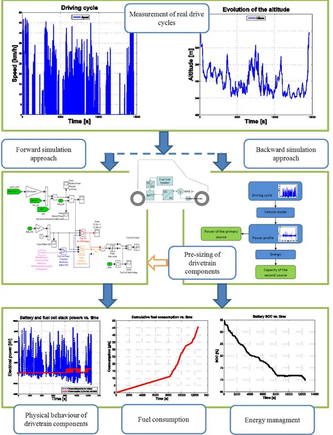
The methodology adopted to design the vehicle powertrain that matches the requirements of postman missions is exposed in Fig. 1. The picture shows the different steps involved in the design process to obtain a well-suited simulation of the MobyPost vehicle. The first step is related to the exploitation of real mission profiles based on monitored data of speed vs. time and altitude vs. time recorded on Postman vehicles during postal delivery missions. The second step concerns the powertrain design procedure including different simulation tools based on backward and forward simulation approaches. Differences in backward and forward modelling approaches can be defined as follow:
- In the backward approach, the target speed and corresponding torque are strictly imposed to the wheels; there is no speed control. In this kind of method, only quasi-steady models can be used and transient effects cannot accurately be taken into account. However, simulations using the backward-facing approach tend to execute quickly.
- In the forward approach, the driver model will accelerate or brake in order to follow the desired vehicle speed. It is well suited to the calculation of maximum efforts, as they are essentially linked to pedals events. A library developed at IFSTTAR LTE, based on Matlab/Simulink language and called VEHLIB [1,2] is used to simulate the MobyPost vehicle with this approach. The formalism used to represent the component models and their interactions in the vehicle model is derived from the bond graph techniques. The approach is based on the law of energy conservation and is more accurate to evaluate vehicle dynamic performances since it can better take into account transient phenomena.
On the one hand, the backward study allows to quickly obtain the size of the powertrain components (fuel cell system, batteries, converters, motor). On the other hand, the forward simulation allows validating the proposed size by simulating the powertrain designed including dynamical response of each component, and by testing different energy control laws with the aim to optimize energy consumption.
2
3
2. POSTAL DELIVERY REAL DRIVE CYCLES
The vehicle must achieve with success a targeted mission characterized by multiple stops and starts and successive phases of acceleration and braking under all-weather conditions. The required duty service is 6 days per week, any time. To clearly define and understand the real requirements for postal delivery vehicles, a first analysis has been carried out and several vehicles of La Poste have been instrumented in different sites (Fig. 2).
All the selected vehicles were equipped with a data acquisition system including a GPS (Global Positioning System) device aiming to measure both the speed of the vehicle and its elevation vs. time. The data were stored at the frequency of 10Hz. Data are related with vehicles from scooter to thermal lightweight cars through small electric vehicles on the French sites of Audincourt, Lons le Saunier and Maîche. For each vehicle and on each site, the collected data are covering one week of postal delivery.
Figure 2: Instrumented vehicles and example of postal delivery mission
All the data acquired are analyzed and filtered in order to make them compatible with the vehicle simulation tools. In most of the recorded files, some data are missing due to communication signal losses with GPS, implying aberrant values in elevation variation or in speed variation. The stage of analysis and processing data is a very important way to ensure a signal without disturbance representative of the raw data collected.
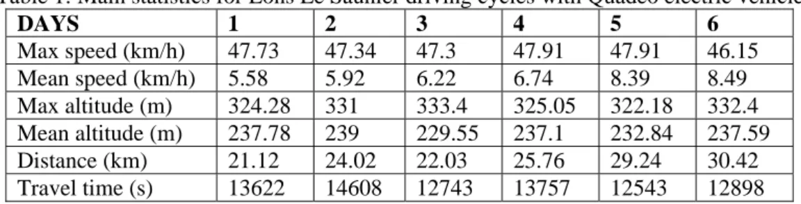
For each recorded driving cycle, simple statistics are made with the aim to quickly show relevant parameters and finally choose the best adapted cycle for simulation stages. An example of these parameters is given in Table 1.
Table 1: Main statistics for Lons Le Saunier driving cycles with Quadeo electric vehicle
DAYS 1 2 3 4 5 6 Max speed (km/h) 47.73 47.34 47.3 47.91 47.91 46.15 Mean speed (km/h) 5.58 5.92 6.22 6.74 8.39 8.49 Max altitude (m) 324.28 331 333.4 325.05 322.18 332.4 Mean altitude (m) 237.78 239 229.55 237.1 232.84 237.59 Distance (km) 21.12 24.02 22.03 25.76 29.24 30.42 Travel time (s) 13622 14608 12743 13757 12543 12898
4
3. MODELLING APPROACHES AND ENERGY MANAGEMENT OF THE POWER TRAIN
The modelling stage is divided in three steps. The first one aims to define the mechanical characteristics of the studied vehicle; the second one to design and size the powertrain components in the chosen architecture in order to use finally the vehicle models on real cycle sollicitations with specific energy control laws. Both backward-facing approach and forward-facing approach are used as simulation methods during this stage.
3.1. CHARACTERISTICS OF THE FUTURE VEHICLE USED IN SIMULATION
In order to establish the energetic model of the vehicle, some parameters of the future MobyPost vehicle need to be set (i.e : weight, aerodynamic coefficient…). Since the vehicle is not built yet, it had been decided that a first step towards the simulation of the future MobyPost vehicle could be to consider the architectures of the Ligier Quadeo (electric vehicle already operating on different sites of La Poste) and the Ducati Freeduck (vehicle developed by Ducati Energia – project partner). The main mechanical and electrical characteristics used for the simulations are given in Tables 2.a, 2.b and 2.c respectively.
Table 2.a: Mechanical characteristics of Liger Quadeo and Ducati Energia Freeduck
Width (m) Height (m) Weight (kg) Transmission
Quadeo 1.427 1.85 650 Mechanical reduction
Freeduck 0.82 1.63 406 Direct
Table 2.b: Mechanical characteristics of Liger Quadeo and Ducati Energia Freeduck
Operating weight (kg) Front surface (m²) Radius of the wheel
(mm)
Quadeo 875 2.138 281.1
Freeduck 566 1.2 253
Table 2.c: Electrical characteristics of Ligier Quadeo
Motor Battery
Type Power (kW) Speed (RPM) Type Voltage (V) Capacity (Ah)
Induction motor
4 3900 Lead-acid 48 177
3.2. FIRST APPROACH - BACKWARD SIMULATION
The first model developed is based on “backward” simulation principle. Considering different architectures and in order to compute the size of the main components in the power train, the model of the vehicle used for the calculations is based on a simplified vehicle’s behavior [3,4,5]. The vehicle is defined as a rigid mass with the same dimensions as the Ligier Quadeo or Ducati Freeduck. The simulation results allow evaluating the power needed by the primary power source based on the fact that the primary source is constantly running at the mean power and the capacity of the secondary power source absorbs the dynamic power solicitations during all the cycle [6].
Three electrical architectures are evaluated in this stage as it is shown in Fig. 3. In the first architecture, the battery bank is directly connected to the DC-bus of the electrical powertrain, setting the voltage value. The electronic converter is then used to adapt the voltage between the fuel cell and the battery bank. In the second architecture, two power converters are used for the energy conditioning: one to interface the fuel cell with the DC-bus, the other to connect the battery to the bus. In the last architecture, only one power converter between the battery bank and the DC-bus is used for the energy conditioning.
5
Figure 3: Electrical power train architectures
The comparison between the three architectures is summarizes in Table 3. By analyzing the advantages and disadvantages, it can be seen that the architecture 1 should be the more interesting regarding to its simplicity, compactness, low cost and correct reliability.
Table 3: Comparison between three architectures
Number of DC/DC converters Bulk Complexity of control Efficiency for high number of start/stop Reliability Cost
Architecture 1 1 Low Low Medium Medium Low
Architecture 2 2 Large High High High High
Architecture 3 1 Low Medium Low Low Medium
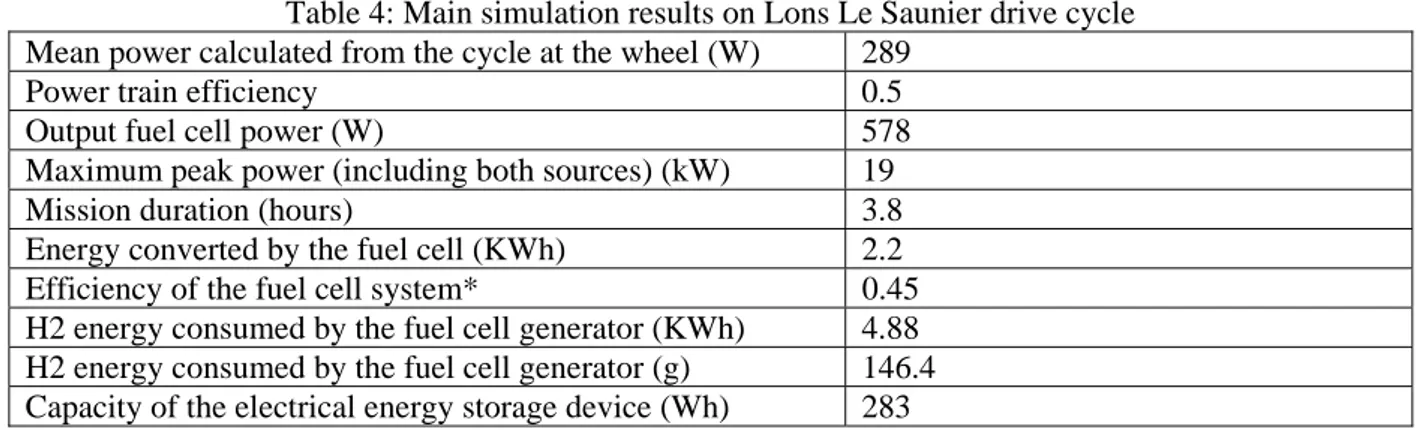
An example of backward simulation results considering architecture 1 with the Freeduck parameters and a postal delivery cycle measured in Lons Le Saunier is given in Table 4.
Table 4: Main simulation results on Lons Le Saunier drive cycle Mean power calculated from the cycle at the wheel (W) 289
Power train efficiency 0.5
Output fuel cell power (W) 578 Maximum peak power (including both sources) (kW) 19
Mission duration (hours) 3.8
Energy converted by the fuel cell (KWh) 2.2 Efficiency of the fuel cell system* 0.45 H2 energy consumed by the fuel cell generator (KWh) 4.88 H2 energy consumed by the fuel cell generator (g) 146.4 Capacity of the electrical energy storage device (Wh) 283
* The value of 0.45 (Lower Heating value) is selected from experiments and tests carried out in the UTBM fuel cell laboratory
3.3. SECOND APPROACH - FORWARD SIMULATION
Once the final architecture is defined and the first sizing of the powertrain components is made, thanks to the backward simulations done previously, a second stage of simulation is realised with the forward-facing approach of the VEHLIB library. At this stage, different energy control laws can be evaluated with the simulated vehicule trying to follow a real drive cycle.
6
The main objective of the strategies developed is the minimisation of the vehicle hydrogen consumption while matching the driver demand. For the MobyPost series - Fuel Cell Electric Vehicle (FCEV) architecture, the inverter input power appears as the sum of the fuel cell generator and the energy storage system contributions (batteries). Consequently, the control strategy has to compute the instantaneous power split between the two sources.
The first strategy developed aims at minimizing fuel consumption and balancing the batteries State of Charge (SoC). Fuel use is minimized with the fuel cell system operating with a good efficiency. This means that the fuel cell system should operate between two powers (cs_min_powr and cs_max_pwr) in order to enable the best possible efficiency as it is shown in Fig. 4. Maintaining batteries SoC higher than a certain rate is needed to be able to provide enough power in the case of a sudden large acceleration. A set of static parameters, which are optimized according to the driving cycle, is used to avoid SoC drift.
Figure 4: Fuel cell system efficiency [%] as a function of the net power [kW]
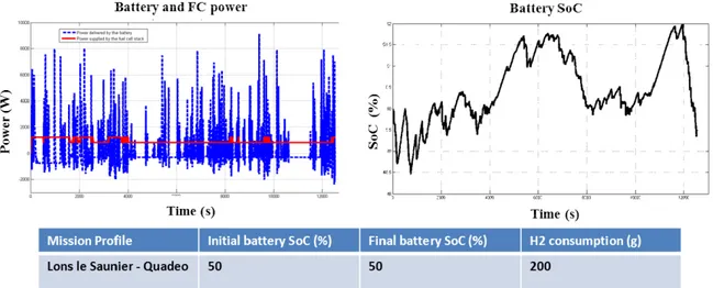
The best efficiency point can be fixed at a constant value corresponding to the nominal / usual operation of the fuel cell generator. Possibly, the point can also be defined as best in dynamical operation [7]. Figure 4 shows for example the maximum efficiency operating range of the fuel cell and gives information on how the maximum efficiency can be tracked during operation. Considering various strategies based on the principles mentioned before, several simulations are made in order to evaluate the best behaviour of the vehicle associated with the minimal hydrogen consumption on different mission profiles. An example of simulation results computed, taking into account an initial battery SoC of 50%, and with the Quadeo architecture following the Lons le Saunier mission profile is given in Fig. 5.
Figure 5: Simulation results with the forward approach of VEHLIB
4. OPERATION IN DEGRADED MODE
As the postal delivery mission induces severe operation of the vehicle and because the developpement of a new electrical drive train is risky, a degraded mode control strategy, derived from the standards control
7
strategy had been strudied. This mode is triggered when one or more components are damaged and not able to supply usual performances. The following components are of concern: fuel cell generator, batteries, DC-DC converter, motor with associated electronic drive. For each component, a State of Health (SoH) indicator is defined: it can be either a boolean or an integer value. Figure 6 describes the inputs / outputs of the proposed degraded mode strategy.
Figure 6: Inputs and outputs of the degraded mode strategy
When the vehicle operates in degraded mode, three types of variables may be affected. The fuel cell current will be saturated to a low value if the fuel cell is degraded. The battery current will also be limited for a low battery state-of-health or when the DC-DC converter (between the fuel cell and the battery) is faulty. If the battery rated capacity decrease, the minimum voltage of the DC bus will be lower than in the healthy case. Finally, the energy management strategy reduces the maximal speed of the vehicle on most of the degraded mode cases.
In the example given in Fig. 7, the degraded fuel cell performances are obtained considering the nominal current – voltage curve and taking into account an additional overvoltage Uadditional_overvoltage (having the form of an ohmic voltage drop [V]. For example: Uadditional_overvoltage = -0.002 × fuel cell current value). The normal and degraded current – voltage characteristics are shown below, as well as the impact of the voltage degradation on the fuel cell net power.
(A) (B)
Figure 7: Comparison between the normal / nominal cell polarisation curve (healthy state) and the adopted fuel cell current– voltage curve representing the degraded individual cell performances (A).
Comparisons in terms of stack power delivery (B).
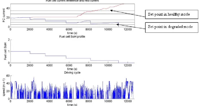
Some simulations were done with the VEHLIB software with different cases of degraded components in the power train. An example of simulation results is shown in Fig. 8 where the control strategy enforces the degraded mode when the fuel cell SoH is progressively decreasing. The fuel cell SoH varies between 0 and 1 and the fuel cell current output is limited. The red line is the current set point when the fuel cell is
0 10 20 30 40 50 60 70 0 0.1 0.2 0.3 0.4 0.5 0.6 0.7 0.8 0.9 1 Current [A] Cell voltage [V]
Polarisation curve in nominal conditions
Polarisation curve with additional overvoltage = −0.002 * Current
0 10 20 30 40 50 60 70 0 200 400 600 800 1000 1200 1400 Current [A] Power [W] In nominal conditions
8
in healthy mode while the blue line corresponds to the real fuel cell current (limited by the degraded mode).
Figure 8: Dynamical simulation of the vehicle drivetrain on the Lons Le Saunier cycle with a fuel cell SoH variation
3. CONCLUSION
The aim of the design and simulation methodology adopted during the first stage of the MobyPost project
has consisted in defining and sizing the vehicle drivetrain in order to simulate the overall behavior and energy needs of the future FCEV dedicated to postal delivery. Special additional care focused on the study of degraded operation modes. The methodology was applied in three main steps. In a first stage, the real use of postal delivery vehicles had been studied with the instrumentation of different ranges of La Poste vehicles on three sites. At each time, data were collected during one week long. The recorded drive profiles became thereafter entries guidelines for simulations. Thanks to backward and forward simulation approaches, offering each of them specific interests, sizing and study of the overall vehicle behavior had been done. The work finally conducted to precisely quantify theoretical energy needs and evaluate the relevance of different energy control laws, both considering healthy and degraded operation modes. The simulation results have now to be faced with test bed experimental conditions; it is the subject of the second part of the MobyPost project work detailed in [8]. The next step will be to evaluate the onboard technology during real postal delivery missions where additional constraints will probably appear due to the challenge of integrating new technologies in real vehicles.
REFERENCES
1. B. Jeanneret, R. Trigui, F. Badin, F. Harel, F. Damemme, and J. Lavy. New hybrids concept simulation tools, evaluation on the Toyota Prius car. INRETS - IFP. EVS16, Beijing, October 1999. 2. R. Trigui, B. Jeanneret, and F. Badin. Modélisation systémique de véhicules hybrides en vue de la prédiction de leurs performances énergétiques et dynamiques, construction de la bibliothèque de modèles VEHLIB. INRETS LTE : Revue Recherche Transports Sécurité n° 83 Avril-Juin 2004, ISSN 0761-8980.
3. M. Jain, C. Desai, N. Kharma, and S. Williamson. Optimal powertrain component sizing of a fuel cell plug-in hybrid electric vehicle using multi-objective genetic algorithm. IEEE Industrial Electronics Conference (IECON 2009), pp. 3741-3746. Porto, Portugal, Nov. 2009.
4. D. B. Q. Caia, D.J.L. Bretta, and N. Brandona. A sizing-design methodology for hybrid fuel cell power systems and its application to an unmanned underwater vehicle. Journal of Power Sources
9
195, pp. 6559–6569, 2010.
5. L. Guzzella and A. Sciarretta. Vehicle Propulsion Systems - Introduction to modeling and Optimization. 1st ed. Springer, 2005. 291 pages.
6. A. Ravey, N. Watrin, B. Blunier, D. Bouquain, and A. Miraoui. Energy sources sizing methodology for hybrid fuel cell vehicles based on statistical description of driving cycles. IEEE Trans. on Vehicular Technology,
Vol. 60, Issue 9.
pp.4164 – 4174.
2011.7. D. Candusso, A. Walter, S. Bacha, and E. Rullière. Modelling, control and simulation of a fuel cell based power supply system with energy management. IEEE Industrial Electronics Conference (IECON 2002). Vol. 2, pp. 1294–1299. Séville, Spain, Nov 2002.
8. S. Faivre, A. Ravey, D. Guilbert, A. Ndiaye, A. Gaillard, D.Bouquain, A. Djerdir, C. Higel, F. Harel, D. Candusso. Design and experimental validation of MobyPost vehicle’s powertrain. FDFC 2013, Karlsruhe.