Publisher’s version / Version de l'éditeur:
Vous avez des questions? Nous pouvons vous aider. Pour communiquer directement avec un auteur, consultez la première page de la revue dans laquelle son article a été publié afin de trouver ses coordonnées. Si vous n’arrivez pas à les repérer, communiquez avec nous à PublicationsArchive-ArchivesPublications@nrc-cnrc.gc.ca.
Questions? Contact the NRC Publications Archive team at
PublicationsArchive-ArchivesPublications@nrc-cnrc.gc.ca. If you wish to email the authors directly, please see the first page of the publication for their contact information.
https://publications-cnrc.canada.ca/fra/droits
L’accès à ce site Web et l’utilisation de son contenu sont assujettis aux conditions présentées dans le site LISEZ CES CONDITIONS ATTENTIVEMENT AVANT D’UTILISER CE SITE WEB.
Technical Memorandum (National Research Council of Canada. Associate
Committee on Soil and Snow Mechanics), 1961-05-11
READ THESE TERMS AND CONDITIONS CAREFULLY BEFORE USING THIS WEBSITE.
https://nrc-publications.canada.ca/eng/copyright
NRC Publications Archive Record / Notice des Archives des publications du CNRC :
https://nrc-publications.canada.ca/eng/view/object/?id=9bc47f55-1065-4597-96bd-e2d2ccc1ee14 https://publications-cnrc.canada.ca/fra/voir/objet/?id=9bc47f55-1065-4597-96bd-e2d2ccc1ee14
Archives des publications du CNRC
For the publisher’s version, please access the DOI link below./ Pour consulter la version de l’éditeur, utilisez le lien DOI ci-dessous.
https://doi.org/10.4224/40001168
Access and use of this website and the material on it are subject to the Terms and Conditions set forth at
CANADA
ASSOCIA TE COMMITTEE ON SOIL AND SNOW MECHANICS
PROCEEDINGS OF THE
SYMPOSIUM ON AIR BUBBLING, OTTAWA, 11 MAY 1961
...
-,
..
'lh..:...••
Sponsored by the Subcommittee on Snow and Ice, ACSSM and the Working Group
on Ice in Navigable Waters of the Canadian Committee on Oceanography.
TECHNICAL MEMORANDUM NO. 70
OTTAWA DECEMBER 1961
Snow and ice are rn ajo r factors in ITlany activities of e c o nornic
impo rtanc e to Canada. It is not surprising, therefore, to find at least four comrn itte e s of the National Research Council directly concerned with these rrrate rial s . These cornrnitte e s consider pr ob Ierns such as the prediction of run-off fr orn rne Itirig snow covers, the prediction of winter ice conditions in the Gulf of St. Lawrence, the rne a sur erne nt of changes that occur in
glaciers and how to keep highways and city streets clear of snow. By
working together closely, they discharge their responsibilities with no needless duplication of effort.
One ice pr oblern that has received considerable attention in recent years is that of rna intatrring water areas that would no r-m alIy freeze over
free of ice for part or all of a winter. The Working Group on Ice in Navigable
Waters of the Canadian Cornrrrittee on Oceanography and the Subcornrnit tee on Snow and Ice of the Associate Cornrn itte e on Soil and Snow Mechanics, two of the cornrnit te e s that are associated with the National Research Council, have given consideration to this p r oble rn , In response to d em ands for infor-rn ation , these coinfor-rninfor-rnitte e s sponsored jointly a conference on techniques for
preventing ice Ior mat ion on lakes, rivers and salt water areas. Invitations
were extended to those actively engaged on this p.r oblemt.o present their
experience and participate in the discussions. Through their contributions
the conference successfully recorded and s umrn ariz ed what is now known
in Canada on rne thod s for preventing the fo r m at ion of ice covers. The Associate Cornrrrittee on, Soil and Snow Mechanics is pleased to have the
opportunity to publish in their Technical Merrior andurn series the Proceedings of this conference and thus to rnake available the info r rn ation then presented.
The As sociate Cornrn itt e e on Soil and Snow Mechanics and the Canadian Cornrn ittee on Oceanography wish to express their appreciation to
all who participated in the conference and contributed to its success. They
wish, in particular, to acknowledge the kindness of the U. S. Navy Hydro-graphic Service for allowing a cornp.let e description of their air bubbling installation at Thule, Greenland, to be presented and discussed.
OTTAWA,
De c erribe r 1961.
( i)
W. E. VAN STEEN BURGH, Chair rn an , Canadian Cornrriitt.ee on Oceanography.
R. F. LEGGET,
Cha.ir rrran , Associate Cornrnitte e on Soil and Snow Mechanics.
Page No.
Conference summary by L. W. Gold
MORNING SESSION Chairman: L. W. Gold
(iii)
Thermal regime of lakes and rivers with reference to air bubbling
systems by G. P. Williams 1
The principles of operation of bubbling systems by W. D. Baines 12
Recent experimental observations on the use of air bubbling systems'
by S. Ince 23
Thermodynamic considerations on the use of air bubbling systems
in salt water by E. R. Pounder 41
AFTERNOON SESSION Chairman: T. A. Harwood
A model describing the physical processes of Project Polynya by Charles W. Senior
Operationsl details of Project Polynya by William A. Dotson
Description of air bubbling systems at Cambridge Bay and Tuktoyatuk, N.W.T. byT.M. Dick
Investigation of a compres sed air bubbler system used for ice melting by W. D. Bonisteel and A. Bergs
Other contributions and general discussion
47
58
70
78
97
APPENDIX A: Summary of reports received on air bubbling installations
APPENDIX B: List of those attending meeting
L. W. Gold, Ch ai.r rna n , Snow and Ice Subcornrnittee of the NRC As sociate Corrm iitte e on Soil and Snow Mc chanic s
The objective of the conference was to summarize the knowledge available in Canada on the use of air bubbling systems for melting or preventing the formation of ice covers on selected areas of lakes, rivers and oceans. It brought together engineers who have designed or constructed such systems and the men who are gathering the knowledge that is still required to determine if an area can be kept ice free and, to design the appropriate system if it can. The merging of their experience at this conference has greatly enlarged the knowledge of how bubbler systems work and their limitations.
Eight papers were presented. Five discussed various
aspects of the design of bubbler systems, the nature of the circu-lation that they induce, and the thermal conditions required to
ensure their successful operation. The remaining three presented
details on the design of specific field installations and .problems encountered in their operation. In addition, special reports on field installations were submitted, some of which were presented
to the conference. All of these reports have been summarized and
are included in the proceedings.
The papers by Williams, Baines and Senior bring out quite clearly that if an ice cover is to be melted, or its formation prevented, either heat must be supplied continuously to the water
surface, or any ice that forms must be transported immediately out of the area to be kept ice free. During the winter, most fresh water lakes are thermally stratified, the warmer water, at a temper-attire between 32.0 and 39. 2°F, being at the bottom. As illustrated by Williams, the warmer water is only slightly heavier than the water in contact with the ice and little work is required to raise it to the surface where the heat it contains can be used to melt ice or prevent its formation. Baines describes how air bubbles, emitted from pipes submerged in the water, will do this work very efficiently, putting into circulation by entrainment not only the water in the irnmediate vicinity of the rising bubbles, but also for some distance from them. Because of the large amount of heat that is usually available in the sub-surface water, air bubbling systems can be used in many lakes in
Canada to keep sites ice free for appreciable periods of time and, in some cas e s, for the whole winter.
In most rivers the flow is turbulent, and for this case calculations by Baines show that the te mp e r a tu r e of the water from
flowing water may not have the heat available for pr eventing ice
for mat i on as does a lake. The success of a bubbling systern installed in flowing water will depend on the conditions at the site, such as
the flow velocity and possible upstream sources of heat. Baines points out that for flow, velocities in excess of 3 ft/sec, the turbulent mixing is great enough that an air bubbling installation would likely have little influence on the formation of surface ice, since this might be prevented by the flow itself. This opinion is supported by the field observation that ice covers form with difficulty when the flow is greater than about 2 ft per sec, and under such conditions the formation of frazil is common.
The use of bubbler systems for preventing ice formation.
rn sea water requires special consideration. As pointed out by Pounder, the temperature at which the density of the water is a
maximum decreases with increasing salt content from about
39
of for fr esh water, to the equilibrium fr eezing temperatur e when thesalinity is 24. 7 parts per thousand. For salinities gr :ater than 24. 7
parts per thousand, as is the case for most sea water, the density does not have a maximum for temperature warmer than the equilibrium freezing temperature. In this case, the convective mixing due to the cooling of the surface water, and associated increase in density, will continue until ice begins to form. The m ea su r ern ent s made at Thule and reported by Senior show that when ice begins to form, the water temperature will be almost constant and very close to the freezing temperature right to the bottom at most sites where bubblers might be used. As in the case of a river, there will be little heat available from the water under the ice cover, for melting ice or preventing its formation. Pounder does point out that if the salinity increases with depth, this could result in some ice melting by the action of a bubbler.
Although stationary sea water would not be expected to have the reserve of heat necessary for ice melting, it is possible
that at some sites tidal or permanent currents carry sufficient warm or more saline water into the ar ea to enable a bubbler system to perform satisfactorily. A possible example of this is the successful installation at Tuktoyaktuk, described by Dick.
The papers by Senior and Dotson show that in cases where the heat reserve has been depleted, the surface currents set up by the bubbler may be sufficient to remove the ice as it forms in the open area. This possibility has led them to consider other systems for
establishing surface flow, such as the "outboard motor" technique which has been reported as successful in the Antarctic (Me Murdo Sound).
under standing of how air bubbler s or surface flow developer s pr event ice cover formation on sea water, and the conditions under which they can perform successfully. Further field observations should be
undertaken to obtain the required information. When this knowledge is available, it should be possible to determine by adequate surveys if the ice cover can be pr evented from forming at a particular ocean site, and what technique should be used. Failures, such as that at Cambridge Bay, described by Dick, might then be avoided.
It was apparent from the papers and discussion that for the many cases where bubbler systems have been used successfully, the design of such systems has been largely, if not completely,
empirical. The material contained in the papers by Baines, Williams,
Senior and !nce, and in a review by Williams (l) should now allow' the design to be placed on a more rational basis. One of the first quantities that should be estimated at a possible site is the rate at
which water must be brought to the surface to prevent ice from forming, or the surface flow velocity required to remove the ice that forms
in the area to be kept clear. It should be possible to obtain a reasonable estimate of these quantities following the same procedure as used
by Williams and by Pounder in the sample calculations presented in their papers.
Baines shows from theoretical reasoning, that the volume of water brought to the surface by a bubbler is likely proportional to (Z)3/2 and (Qa)2/3, where
セ
is the depth of the source of bubbles and Qa is the volume of air discharged from the orifice. There appears to be no suitable observations available that can be used to test the above theory. A field study by Kaitera (2) does indicate that the amount of water brought to the surface in a given time by one bubbler isproportional to the depth raised to the power of about 3/2 and to the air discharge rate raised to a power less than 1. Although it is still not possible to calculate the volume flow that would be caused by a bubbler ejecting air at a given rate and given depth, the theory does allow one to appreciate the influence of depth and air discharge rate on this flow.
One conclusion that can be drawn from the foregoing is
that if the volume of water brought to the surface in a given time by on e bubbler is proportional to the rate of air dis char ge raised to a power less than one, then for a given total air discharge rate, the larger the number of orifices, the greater is the volume of water put into cir cu-Iat ion . This conclusion is born out by the field observations of
Kaitera (2). It is also a possible explanation for the observation by Hindes that the system with which he is familiar, which dischar ges
circulation. Bubble size might be a factor in producing this improved circulation, but, as pointed out by Baines, for the normal field
installation this size probably does not dep en d on the diameter of the orifice, but may depend on the rate of discharge of the air.
The papers, reports and discussions contained in this Technical Memorandum of the Associate Committee on Soil and Snow Mechanics, record clearly the present state of our knowledge of the use of bubblers and flow developers for preventing the formation of an ice cover. They indicate also that further information is r equir ed on the dependence of the volume rate of induced flow on depth of bubbler, rate of air discharge and characteristics of the bubbler system, so that the design of such systems may be based more directly on the requirements of the site. The preliminary investigations described
by Ince and Baines are an excellent beginning of the accumulation of this knowledge. It is hoped that this work will.continue. The members of the Snow and Ice Sub-Committee and the Working Group on Ice in
Navigable Waters hope also that the material pre se nt ed in this publication
will, in addition to being a us eful contribution to engineering .
practice, act as a stimulus for further advances in our ability to combat ice.
REFERENCES
(1)
(2)
Williams, G. P. A Study of Winter Water Temperatures and
Ice Prevention by Air Bubbling. Eng. Journal, 44, (3),
March 1961, pp. 79 -84.
Kaitera, P. Keeping Water from Fr eezing by Means of
Com-pressed Air. Int. Union of Geod. and Geophy., Int. Assoc.
of Sci. Hyd., Vol. 2, pp. 390 -398, 1948.
WITH REFERENCE TO AIR BUBBLING SYSTEMS
by
G. P. Williams
Air bubbling systems have been used successfully to melt ice or prevent its formation in lakes, rivers an do c e an areas, but there are cases where they have been unsuccessful. If the action of a bubbler results in the melting of ice or the prevention of its formation, the bubbler must have brought, to the surface, water containing sufficient heat for this purpose. If the water does not contain the required heat it is unlikely that a bubbler will open a hole in an already established ice cover. These
facts indicate that before a bubbler system is installed careful consideration should be given to the heat reserves available at a proposed site, and the heat losses to be expected, particularly in those cases where the temperature of the water is just at or slightly above the freezing point. The purpose
of this paper is to discuss these thermal factors.
When a lake cools during the fall and early winter, convection currents continuously replace the surface water with the warrner, lighter water below. After the temperature of the water has dropped to 39. 2°F, the density of the surface water decreases with further drop in temperature and will remain at the surface until cooled to the freezing point. An ice cover will then form. In a typical fresh-water lake of Central Canada the water temperature directly under the ice will be at 32°F, and will increase with depth to a maximum of between 35 to 39. 2 ° F at the bottom. The
change in water temperature with depth at a particular site will depend upon factors such as the water depth and the cur.rents in the lake.
When a river cools, its water is kept at nearly the same
temperature by mixing. Under these conditions, an ice cover will not
start to form until the temperature of all the water in the river is close to 32.0 ° F. The average temperature of the water under the ice cover of rivers depends to a certain extent on the heat input from upstream sources, but it can never exceed 32.0°F by more than a fraction of a degree (1). In a typical river, the temperature at the water-rce interface .will be
In either fresh-water lakes or rivers there is only a slight difference in density between the water just under the ice cover, and the water at the bottom. Thirty-two cubic feet of water at 39. 2 ° F resting on the bottom will weigh only about one quarter of a pound rno r e than the s arn e vo Iurn e of water at 32 ° F just under the ice cover. The amount of work expended in raising this volurne of water (2000 pounds) to the surface will be approximately the s arn e as that used to raise one quarter of a
pound the same distance in air. With these slight density differences any method which will induce mixing, such as a flow of air bubbles from the bottom to the surface, will result in a significant movement of warm water to the surface with very small ener gy input. . The heat in this warmer water can then be used to melt surface ice or to prevent its formation. The rate at which ice can be melted in practice at successful bubbling installations indicates that the thermal exchange between water and ice under these conditions is quite good.
The heat available for melting or preventing ice formation is stored not only in the water under the ice cover, but also in the material underlying the lake or river. The ways by which this heat is used or lost at an air bubbling installation is in melting ice, th r ou gh evaporation, convection and radiation from the open water surface and by conduction through the surrounding ice cover. Figure 1 shows the different sources of heat and heat losses which should be considered in the design of air bubbling systems is rot included, as in most cases it is too small to be of significance.
HEAT SOURCES
Q and Q - Heat Available from the Water
e a
The magnitudes of Q and Q
a e
known, if the depth of the water body is known, and if the area of influence of the air bubbling unit can be defined. Water temperatures セョ、 depth can be measured readily to the accuracy required for a reasonable estimate of the heat available. The area of influence of the air bubbling jet and the resulting water temperature distribution is a question which is not so
easily answered. The papers by Baines and Ince give further consideration
to this factor.
The heat available at a temperature above 32°F in the water immediately under the opening cr eated by the air bubbler is called Q in
e this paper. The heat in the water under the ice cover for some distance
surrounding the open hole is called, in this paper, Q or advecti ve heat. a
If the te mp cr atur e of one cubic foot of water is lowered 1°F, 62.5 Btu of heat are released. In the case of lakes, where the rn e an ternperatur e of the water below the ice can be lower ed 4 to 7 ° F by air bubbling, the heat released is from 250 to 440 Btu/cubic foot.
In river water where the average temperature of the water below an ice cover is only a fraction of a degree above 32°F, the amount of heat available is no r rna.Ily much less than for a lake. Because the amount of heat available from one cubic foot of water is small, the heat that can be brought to an air bubbling site from upstream sources is especially important in determining whether air bubbling installations will be succes sful at a
particular site in a river.
Q
b - Heat Flow from Bottom Material
The heat that can be supplied from the bottom of a lake or
ri ver can be estimated if the thermal properties and density of the bottom
material and the temperature gradient in the material are known. Field
rn e a su.r e merits of temperature gradients, density and therm.al properties for a particular site are usually not available. Estimates can be rn a d e from a knowledge of the material and the size of the temperature gradients likely to be encountered.
For example, if the underlying rnaterial is granite, using an assumed thermal conductivity of 0.0045 Btu/ft2 OF/in. sec (2), and an assumed temperature gradient of 0.1 to 0.15°F/in., the heat flow would be app r o xi m at e l y 2. 2 Btu/ sq ft/hr. If the underlying material were silt
loam with a th e r mal conductivity of les s than half that of gr anite, under the same temperature gradient, the calculated heat flow would be 0.5 to
1.0 Btu/sq ft/hr. Nybrant (3) states that in latitude 50 to 60N, the heat flow from typical bottom material in October is approximately 1.8 Btu/ sq ft/hr; in Dec. to J'an , , 1 to
1.
8 Btu/ sq ft/hr, and almost negligible in April.Compared to the heat available from the water under the ice cover, the heat supplied by the bottom material will probabl y be quite small. But where the reserves of heat are critical, such as for shallow water, or a flowing river, the heat supplied from the bottom rn at e r i a l
can be important particularly if this heat can be obtained from comparatively large areas.
As in the case of heat stored in the water, there is a Ii rnit to the amount of heat available fr orn the bottorn rn at e r i a l , As already stated, under natural conditions the heat flow gradually diminishes Ir o m 1.8
early stages in the. operation of an air bubbling system the temperature gradient in the bottom material will probably incr ease, resulting in gr eater heat flow. This may result, however, in the ground heat reserve being
depleted sooner than is normal for the site.
HEAT LOSSES
Q - Heat Used to Melt Ice
rn
To melt, ice r equir es 144 Btu/lb or 9000 Btu/ cu ft. The amount of heat required to melt ice will be directly proportional to the thickness of the ice and the area to be kept open.
Q - Heat Loss to Atmosphere from Open Water
o
In the case of an open body of water under winter conditions, there can be large heat losses from the surface to the surrounding air. This heat los s can be estimated by calculating or rne a sur in g net radiative, evapo r ati ve and convective heat losses for the atmospheric conditions that
prevail. This energy balance approach to estimating heat losses requires
quite detailed meteorological records, which are normally not available for a specific site, and even when available, require so many assumptions for the calculations that the results are often not reliable.
For an estimate of surface heat losses under field conditions.
the use of empirical formulae is usually more practical. Various empirical
formulae have been given (3, 4) which relate heat losses to the air -water
surface temperature difference. These formulae neglect many factors
such as wind velocity and depth of water, but the fact that they give a reasonable estimate under most conditions and that only air temperature and water temperature records are needed, make them useful for practical application. The range of heat losses reported vary from approximate ... y 3.5 to 5.0 Btu/sq ft/hr per degree Fahrenheit water -air temperature difference. For a 200
F air -water temperatur e difference, the heat loss would be from 70 to 100 Btu/sq ft /hr.
Q - Heat Conducted Through Ice Cover
c
The rate of heat los s through an ice cover is much less than the heat loss from an open water surface under the same atmospheric conditions. The heat loss would be further reduced if the ice were covered with snow.
The heat loss through 24 in. of ice for an average air temperature of about 10°F will probably not exceed 10 to 15 Btu/sq ft/hr. The heat loss with 12 in. of snow on top of the ice, under the same conditions, will probably not exceed 1. 0 Btu/sq ft/hr. This compares to 70 to 100 Btu/ sq ft/hr for an open water surface.
If the temperature gradient through the ice or snow cover is measured, and the thickness and density of the cover are known, values for heat flow through ice and snow can be calculated. If the water is not moving, most of this heat loss is associated with the forming of new ice, and comparatively little is from the water beneath the ice.
Because the amount of heat used in melting the ice and the amount of heat lost from open water surfaces are large in comparison with heat losses through the ice cover, the size of the open hole should be kept to a minimum to conserve the heat that is available in the water.
Q - Heat Used in Melting Snow Falling in the Open Water
J
If the air bubbling operation is in an area subject to heavy snowfall or drifting snow, heat will be used in melting any snow that falls into the open hole. Assuming that the temperature of the new snow is close to 32°F, it requires approxirnately the same energy to melt 10 in. of new snow as it does to rnelt 1 in. of ice. At sites where the amount of heat available is likely to be critical, the heat required to melt the snow that falls or drifts into the hole could be important.
SUMMAR Y OF HEAT SOURCES AND LOSSES
Table I presents a summ.ary of the heat sources and heat losses and a comparison of their rnagnitude for various as sumed conditions of operation. In this sample calculation the heat available from 30 ft of water over a 7 -day period, when the area of influence of the bubbler
equals the open area, would, under the most favourable conditions, just balance the expected heat losses. If the area of influence of the air bubbling unit is five tirn e s the open area, the heat available would enable the operation to be carried on for at least 21 days. If the depth was
increased five times, the operation could be carried on for 3 to 4 months.
These calculations illustrate that if the water temperature under the ice cover is a few degrees above 320
F, the length of time a bubbler system can be operated successfully will depend mainly on the volume of
water influenced by the bubbler and the size of the open area. They show also that the relative i rnpo rtan c e of the heat losses from the open area increases with the length of time of operation. For example, in the case of the lOa-day period, over 95 per cent of the total calculated heat loss is from the open water.
EXAMPLE OF AIR BUBBLING TRIAL
In the literature on air bubbling installations there are relatively few reports that give quantitative m e a.s ur ern ent s on the heat available
or the heat losses during a particular operation. In order to show the relative magnitude of heat losses and gains under actual field conditions the results for one bubbling trial are presented in this report.
The air bubbling trial was carried out from 26 January to
1 February 1960 under the auspices of the Hydraulics Laboratory, Division of Mechanical Engineering, National Research Council. The air bubblin g equipment consisted of a single air -line installed on the bottom of a
tank 200 by 400 ft. The water depth was about 7. 3 ft . . The total ice thickness at the beginning of the test varied from 16 to 17. 5 in.ithe ice was overlain by approximately 4 in. of snow. Continuous operation of the air bubbler at an air flow rate of 1 cfrn over a 7 -day period removed ice from a 1,500 sq ft area. Before the test, the rn e a s u r e d water temperature profile was fairly typical for a shallow tank, being approximately 39 ° F
from the bottom of the tank to about 3 ft under the ice cover, then decr easing to 320
F at the ice -wat er interface.
By measuring the water temperature at regular intervals it
was possible to calculate 0 and 0 , the heat made available from the water.
e a
By measuring the arriourrt of ice melted and the arnourit of new snow, the heat used in melting the ice, 0 , and the heat required to melt the snow,
rn
o ,
were calculated. 0 , the heat loss to the atmosphere through the ices c
cover surrounding the open hole was neglected because both the upper and lower surfaces of the ice cover were at 00
C. During the period of test the average air temperature was 17. 5°F as recorded at a nearby meteoro-logical site. Using relationships previously developed (4, 5), the average heat los s from the open water surface was estimated. The only heat that was not measured and could not be calculated with reasonable' accuracy was 0b' that from the bottom of the tank.
particularly severe, about 60 per cent of the heat was utilized in melting the ice, about 39 per cent was lost to the atrno sp h e r e from the open wat e r
surface, and 1 per cent us ed to m e lt new snow. The significant featur e of this trial was that over 95 per cent of the heat used to melt the ice and prevent ice fo r mation ca m e from the water under the ice cover surrounding the open hole. These results show that an air bubbling unit will put into
cir cul at i on a volume of water rnu ch lar ger than that di r ectly under the hole opened by the bubbling action. If this advecti ve heat
0 ,
had not beena available, the heat,
O
2, stored in the water under the opening would have veen sufficient to melt only about 2 per cent of the ice which was melted.
It is interesting to note that if the thermal reserve is exhausted, and water in an open ar ea is cooled down to 00C, further cooling and mixing would probably result in frazil formation. Frazil consists of many small disc-like particles of ice which soon conglomerate into slush and floating ice globules. In this regard, a condition might arise where the formation of fr azil could be us ed to advantage. If the ice particles and slush could be swept away either by natural currents or artificial means, it is possible that the heat released during freezing could balance the various heat losses and thus maintain an open hole in the ice. These conditions apply to open water areas in fast flowing rivers and to small op enin g's observed at bridges, piers, etc., where natural river currents have sufficient velocity. For a srnal l tank as in the example given, however, it is unlikely that frazil formation could be us ed to advantage.
CONCLUSION
The thermal reserve in lakes and rivers at a potential site for an air bubbling installation can be calculated with sufficient accuracy if water temperature profiles are measured, if the water depth is determined, and if the area of influence of the air bubbling unit is know. The heat losses to be expected can probably be estimated with sufficient accuracy if air temperature can be predicted and the thickness of the ice to be melted is
known. In many cases where the thermal reserve is adequate, a detailed
knowledge of the heat available and the heat los ses to be expected is not
necessary. Where the thermal reserve is likely to be critical at a particular site, calculation of the expected heat balance during the operation of an
air bubbling system should be made to determine whether the system will be succes sful ,
ACKNOWLEDGEMENTS
The author is indebted to Mr. L. Gold for most helpful discussions during the preparation of this paper. This is a contribution from the
Division of Building Research, National Research Council, Ottawa, and is published with the approval of the Director of the Division.
REFERENCES
(1) Baines D. W. On the Transfer of Heat from a River
Sheet. Presented at 1961 Hydraulics Conference,
Soc. of Me ch , Eng. and the Eng. Inst. of Canada. 8-11 May 1961.
to an Ice American
Montreal,
(2) Jen-Hu-Chang. Ground Temperature, Vol. I, 300 p. Harvard
University, 21 June 1958.
(3) Nybrant G. Water Temperature in Winter in a Pond and its
Dependence upon Flow. Seminar, Ice Problems in Hydraulic Structures, 8th Congress Int. Assn. for Hydraulic Research,
1959.
(4) Williams G. P. Winter Water Temperatures and Ice Prevention
by Air Bubbling. Engineering Journal, Vol. 44, Mar ch 1961,
p. 79 -84.
(5) Williams G. P. An Empirical Method of Estimating Total Heat
Losses from Open Water Surfaces. Seminar, Ice Problems in
Hydraulic Structures, 8th Congress Int. Assn. for Hydraulic Research 1959.
ESTUv1ATED HEAT SOURCES AND HEAT LOSSES UNDER VARIOUS ASSUMED OPERATING CONDITIONS FOR AIR BUBBLING SYSTEM IN FRESH WATER LAKES
-7 days 21 days 100 days
HEAT VALUES UPON WHICH 30' depth 30' depth ISO' depth
CALCULATIONS BASED ar ea influence 1 ar ea influence 5 ar ea influence 5
=
-
=
-
=
_.
HEAT SOURCES open area 1 open area 1 open area 1
Btu/ sq ft of open Btu/sq ft of open Btu/ sq ft of open
water water water
Q b
o -
2.0 Btu/ sq ft/hro -
O. 5 x 10 3o -
1 x 10³o -
5 x i03.
-250 - 440 Btu/ cu ft of water 3 3 38 - 65 3 Q 7 - 13 x 10 8 - 13 x 10 x 10 e 250 - 440 Btu/ cu ft of water 3 37 - 65 3 x 10³ Q 7 - 13 x 10 x 10 187 - 325 a . ._
. TOTAL 14 - 26. 5 x 10³ 45 - 79 x 103 225 - 395 x 103 HEAT LOSSES 9000 Btu/cu fi of ice- x 103 3. 3 Q 9 - 9 9 - 9 x 10 9 - 9 x 10 m 12 inches of ice 70 - 100 Btu/ sq ft/hr for 3 3 169 - 240 103 Q 12 - 17 x 10 35 - 51 x 10 x a200 F air -water temp diff,
Q 900 Btu/cu ft of new snow/ 1 - 1 x 10³ 3 - 3 x 10³ 13 - 13 x 103
s week Q Assume 0 0
-c -x 103 47 to 63 x 103 191 to 262 3 TOTAL 22 to 27 x 10 MMBMMセMMLセ .---
"---'--'-"'---,-- .. -...0DISCUSSION
A. BREBNER inquired if the work done by the compressor was an important factor in melting ice or preventing its formation.
G. P. WILLIAMS replied that the horsepower 01 the compressor was very small compared with that required to keep the area ice -free.
J. N. HINDE pointed out that the contribution to the heat lost due to
drifting snow may be underestimated. He inquired whether the rate of
circulation figures applied to stagnant water; he also pomted out that the heat losses would be much greater if the top water were not stagnant.
G. P. WILLIAMS replied that the calculations used for the example in
the paper drd not make allowances for drifting snow. The values used
for calculating heat losses generally applied to stagnant water. Values reported in the literature for heat losses from rivers, however. fall within the range of values presented in the paper.
WILLIAMS then asked why surface losses should be greater if the water had been In motion.
J. N. HINDE replied that the convective loss from a water surface depends upon the wind velocity. He suggested that the relative wind velocity would be greater between air and moving water than between air and stagnant water.
E. N. KING asked if the heat loss could be reduced by erection of a plastic house structure over the system.
J. N. HINDE reported that boards had been used successfully to prevent the open water in the hole from freezing by keeping out the snow.
G. P. WILLIAMS considered that a plastic cover would reduce the heat los s but the cost of such structures would make them impractical for many ins tallations .
F. G. BARBER asked if there were any observations on the effect of the bubbler on temperature distribution within the lake.
L. W. GOLD replied that this would come out in discussion later in the day.
SNOW
Co.
セ
BOTTOM
I
I
I
I
AIR BUBBLING UNIT
OPEN
I---'-_ _セ _ _- - - - J
WATER
Q
セ
Q
e
セ
FIGURE I
HEAT AVAILABLE AND HEAT LOSSES
DURING
AIR BUBBLING OPERATION
THE PRINCIPLES OF OPERATION OF BUBBLING SYSTEMS
by
W. Douglas Baines
The function of the air bubbler is to increase the transport of heat from a body of water to the ice cover or open upper surface. In this paper the rate at which this heat transport takes place will be discussed. It has been shown in the previous paper that there are many cases in which adequate heat exists in the body of water to maintain a steady flow through an open upper surface. Ideally, the air bubbler should be designed for the minimum rate of heat transport so that the heat in the lake or river will be available for the maximum length of time. This is not feasible because of several gaps in the theory which p r event the complete detailed analysis from being made. Nevertheless, sufficient is known of the heat flow so that the general principles of operation can be delineated. It is thus possible to avoid serious mistakes in the design of air bubbler s .
The source of heat for the air bubbler lies in the excess temperature in the lower layers of the water. The bubbler induces a
vertical current of water which carries this heat to the upper levels and against the under side of the ice sheet. Thus it is the flow pattern
of the water curl' ent which is of primary inter est to the engineer. From an experimental study of this flow pattern (l) and som.e field observations, the author has obtained a detailed picture of the general characteristics. These will be described in the following paragraphs.
FLOW PATTERN IN THE WATER
At very low air discharge rates, i , e. of the order of 0.01 cfrn, the air issues from the air bubbler hole as individual bubbles of
uniform size. These then proceed vertically upwards in a relatively straight line. For larger air discharges, however, the bubbles issue from the orifice in a heterogeneous rni xtu r e , the sizes varying from about 1/16 up to 1 inch in di arn et e r , The bubbles rise at varying rates
depending on their size and oscillate rapidly from side to side. The
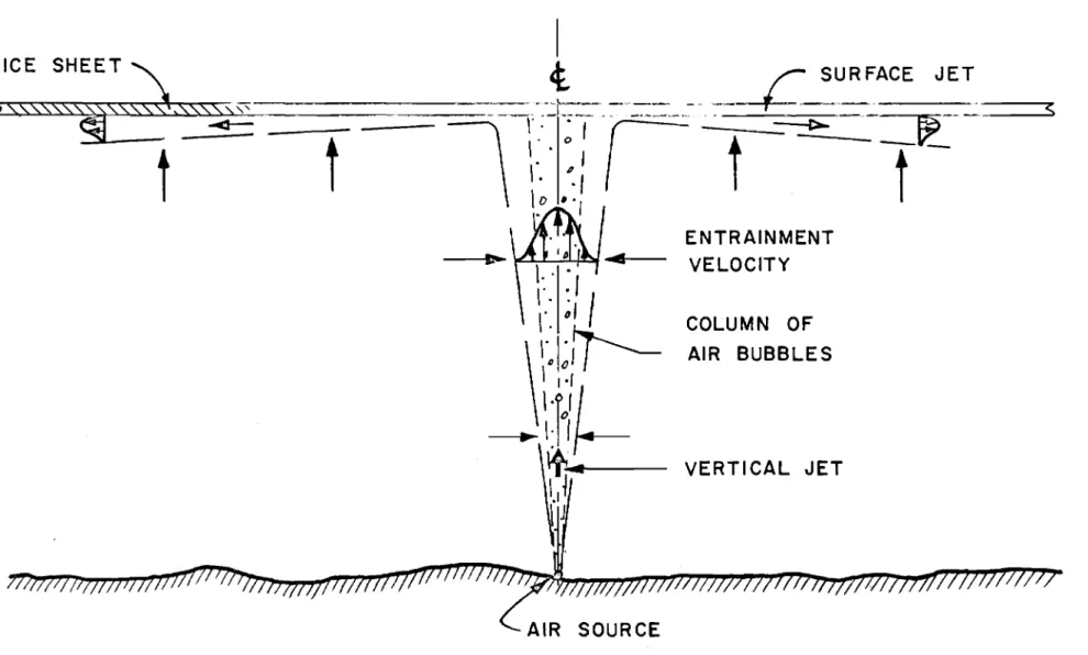
lar ge bubbles induce turbulence which move the smaller bubbles laterally. Thus the size of the clouds of bubbles increases with vertical distance above the orifice. It appears that all bubbles are contained in a cone with a total included angle of 120
as shown in Fig. 1.
It might be expected that the size of the air bubbles depends
Lセ
on the size of 'th e opening through which the air is forced and -a.ls o the
air dischar ge rate. However, measurements made by the author confirm
the analysis of Silberman (2) that the size distribution is independent of the orifice size in the practical range. For orifices 0.04 in. diameter and lar gel' the bubble characteristics depend only on the air dischar gee Thus it is not feasible to vary the bubbler operation by varying the size of the holes. This influences only the pressure loss in the supply system.
The effect of the bubbles, however, extends beyond the cone
containing them. Measurements show that there is a vertically induced
velocity extending about twice the distance laterally. This water flow is induced by the rising air bubb l e column. Each bu bb l e exerts a force on its surroundings proportional to its bou ya,ncy. Thus the water around the bubble is accelerated and rno v e s upward. This motion is transferred to the water beside the bubble column by viscosity a.n d lateral turbulent
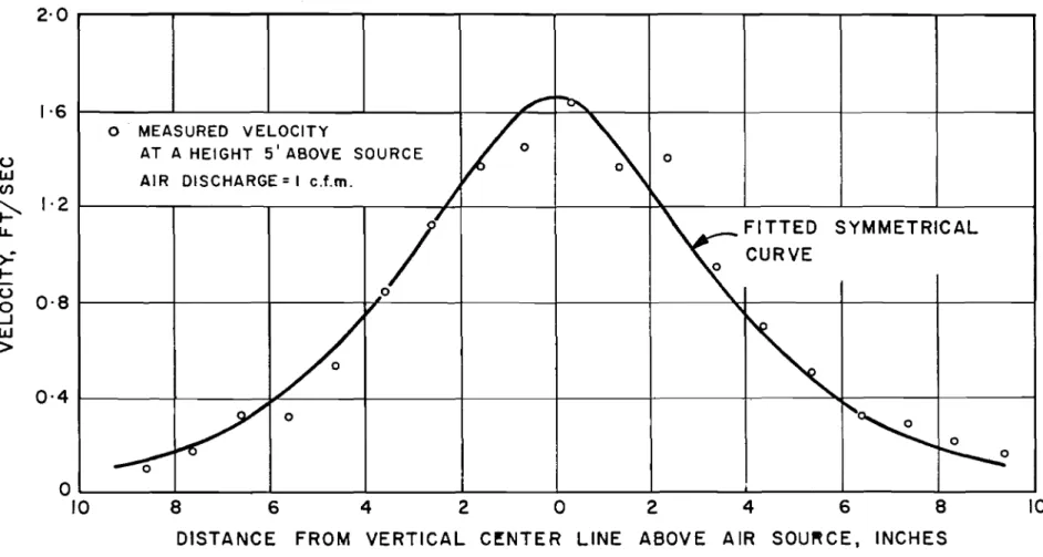
fluctuations. The result is a jet of water moving upward with a maximum
velocity imrnediately over the air source and decreasing along an s -curve radially outwards as shown on Figs. land 3.
The force exerted by the air bubbles on the surrounding water is roughly constant during the period of ascent. If the installation is in very deep water the effect of co mp r e s sibilitv is such that the bubble expands as it rises. In practical situations, however, this expansion need not be considered unless the depth is of the order of 100 feet or' more. Thus it can be deduced that the momentum of the water jet must incr ease steadily as it proceeds upward. Me a su r e me nt s show that the peak velocity in the water jet is constant and thus the increase in rriorn eritu rn is
ac-complished by a steadily widening jet. The most significant practical conclusion of this analysis is that the volume of water transported and the total rnomentum of the vertical jet increases with the depth of
sub-mer gence of the bubbles. Thus the deeper the body of water the more
cheaply the bubbler can be operated.
Since the vertical jet is increasing in volume with distance above the source there must be a lateral flow to supply the fluid. This is commonly r eferr ed to as entrainment or entrained flow and is noted on Fig. 1. This steady inward flow to the jet which has a velocity of the order of a hundredth of a foot per second greatly increases the ar ea influenced by the air bubbler. The heat convected to the vertical jet by ent r a in rn ent is several orders greater than that which could be obtained by conduction.
The increase of momentum of the vertical jet with height is the major advantage of the air bubbler over the alternative sy stern s of
inducing a vertical flow. A jet of water injected at the bottom or a
convection curr ent from a heat sour ce both have constant momentum with height. It can be shown that the energy of these jets decreases with
height and thus the eff e ctiven e s s for melting an ice sheet decreases with depth of submergence. The air bubbler has, of course, an additional advantage which greatly simplifies construction and that is that the orientation of the source is i.mrn at e ria l . The air bubbles and hence the water jet rise vertically r e ga r dl e s s of the dir ection of is sue of the air jet. Such is not true of the dir ect injection of water.
One measure of efficiency of the air bubbler is tb err atio of flow of water induced to the flow of air. This is surprisingly lar ge because of the rno rn eritum increase discussed above. Me a s u r ern errt s made by the author in a water depth of 5. 5 feet with an air dis char ge of 1 cfrn indicated a discharge ratio of about 120. Thus the mass of water rno v e d per unit rn a s s of air injected is 800 times this value or about
100, 000 and hence the practical bene fit of the air bubbler as a rm xrng device. It has been reasoned that this flow ratio should be a function of the air dischar ge
0a
and the depth of submer gence z . All availabledata leads to a relationship of the form
o
wC2
a a:3/2 z
but this has not been verified over a large range of operating conditions. Thus the characteristics of the vertical jet cannot be accurately predicted.
SURFACE JET
Upon reaching the water surface the air bubblers stop but the momentum of the water jet is converted into a radially spreading surface jet. This is relatively thin (6 inches or less) and hence of rather high velocity. The velocity distribution is a maximum at the
free surface if it is open (note Fig. 4) and a maximum close to the surface if an ice cover exists. Measur ements show that the surface jet is quite
steady in spite of the unsteady oscillations of the vertical jet which forms it. Furthermore, the surface jet is radially symmetrical s o that
uniform ice melting effects can be expected. .
The radial spr ead of the surface jet has the general
characteristics of free turbulence. Kinetic energy is obtained entirely from the vertical jet and hence must decrease in the direction of
flow. Analysis indicates that the maximum velocity should decrease
inversely proportional to the radial distance and measurements confirm this trend. The decrease of rna xi rnu rn velocity is accompanied by
thickening of the jet and entrainment of water on the under side. Con-sequently' the velocity of the surface jet rapidly dissipates and it is absorbed into the general pattern of cir culation.
LARGE SCALE CIRCU LATION
It has been seen that the vertical and surface jets consist
entirely of water which has entered each jet from the side as entrainment. The streamlines of the flow field must thus be perpendicular to the jets and, since the body of water was originally static, must be connected to the dissipated surface jet. It can thus be deduced that the Ia r ge scale
circulation induced by the air bubbles is a giant ring vortex as shown on Fig. 2. The flow velocities are very small everywhere except in the jets and decrease with distance away from the bubbler. 'I'h e s e are not, however, zero and thus the zone of influence of the bubbler cannot be clearly defined but tends towards the whole body of water. The pattern drawn on Fig. 2 is for an infinite lake. If the bubbler is near a wall, the streamlines are closer together and the return velocities larger. In practical cases the distance to a boundary of several hundred feet can produce noticeable proximity effects.
TRANSPORT OF HEAT
The transport of heat by the air bubbler has two distinct phases: the convection of heat fr o m the bottom of a lake by the vertical jet and the transfer of heat to the ice or open water surface by the
surface jet. The first is a simple mixing process which is relatively easy to analyse but the second is a problem in turbulent shear flow which is relatively difficult.
When the air bubbler in a lake is fir st started the vertical jet moves through the natural temperature gradient and the volume of flow increases steadily. Mixing is so intense that the jet has a virtually constant temperature at any given depth. This temperature reflects the integrated total of the heat of the entrained water. Thus the temperature at any point can be obtained by calculating the rate of entrainment and multiplying by the local temperature. If broad assumptions are made about the temperature gradient and the rate of entrainment then it can be shown that the vertical jet temperature 'at
the surface is roughly the lake temperature at mid-depth. More
accurate analysis shows that the jet temperature is actually slightly less than this figure but for rough design purposes this approximation suffices. ill rivers and other cases where the water is mixed temperature gradients do not exist and the air bubbler does not transport heat from the lower levels. This is also true of the later stages' of operation in a lake. The circulation pattern of Fig. 2 shows the means by which the mixed water of constant temperature returns to the bottom and thence back into the vertical jet. This means that the temperature along a streamline would be constant and hence the whole field would come to a constant ternperature were not heat conducted laterally from more distant parts of the lake into the circulation pattern.
Considering the surface jet in detail it is seen that this provides a fast moving zone of water very close to the under surface of the ice sheet. This surface must of necessity be at 320
F and thus the jet tends to sweep away the cold film in immediate contact with the sheet and replace it with the warmer water from below. It is this velocity effect that leads to the large melting rates of the ice. The mathematical statement of this effect as a rate of heat transfer is most clearly presented in the equation of Sidorov (3)
v = 1
2 c
"
(I)in which v
=
Nusselt number=
k セ T is primarily a statement of therate of heat transfer; q. in Btu/ft2 sec divided by A T. the temperature of the het above 320
F. r the radial distance away from the air bubbler
centr e line. and k the conductivity of the water ar e r elati vel y uniform among all of these applications. c. is a shear coefficient dependent
"
on the flow field which can be determined from one of the studies of wall jets such as that of St ga.l l a (4).u r Re is the Reynolds number of the
jet. Iv and thus is primarily an expression of u
j ct velocity, v being the kinematic viscosity of the water. The final Ia cto r Pr is the Prandtl nu rnb e r of water at the freezing point and has tbe value 13.6. This is relatively lar gc cornpa.r e d to most engineering situations indicating that the fluid properties are conducive to heat transfer.
The equation given above is not particularly useful in this fo r m , However, the shear coefficient can be approximated fr orn Sigalla results and thus
== 0.08 (2)
As noted above u
1 cannot be evaluated £rOlTI the imposed conditions and thus Eq. (2) is not directly applicable. However, as an example, take typical values of the conditions in a surface jet at radius of 1 foot a rna xirnurn velocity of 1 ft/ sec. The resulting heat transfer rate. will be found from Eq. (2) to be
== 0.04 Btu/ft2 sec 0 F.
This is the same order as that existing in a fast flowing river (5) and this comparison leads to the conclusions that
(i) the action of the air bubbler is identical to that of a river flowing under an ice sheet
(ii) if installed in a river with velocities of 3 ft/ sec or
greater the bubbler will have no effect on the flow. This is because the air bubbler cannot materially increase the natural heat transfer rate. There will, of cour s e , be situations of lower velocity in which the bubbler will be effective. It is the writerrs opinion that the velocity will need to be les s than one foot per second for the installation to be economically feasible.
As the surface jet flows outward it becomes cooler due to loss of heat and by entrainment of water from below (if a temperature gradient exists). Thus the heat transfer rate, q , decreases with radial distance. The actual effective distance depends on water
temperature and the existence of an open water surface. Thus one
cannot predict the optimum spacing of bubbler s in any practical installation.
CHIMNEY VERSION OF THE AIR BUBBLER
It has been suggested that installing a vertical open -ended tube above the air bubbler ending just below the ice surface would
increase the effectiveness. From the above discussion it can be seen
that such a tube WJuld eliminate the entrainment by the vertical jet and thus result in a more concentrated and faster surface jet. It would also deliver warmer water as long as temperature gradient exists.
However, the volume of flow would certainly be les s than that for a simple bubbler SO·it is not possible to conclude that the total effect would be an i.mp r ovc m cnt ,
REMARK
The above is an outline of the flow mechanism of an air bubbler. It is hoped that it will lead to a better under standing of the principles underlying its operation. However, the detailed analysis of any given installation cannot be perforrned with accuracy by methods now available. Thus the engineer must experiment with pilot installations if alar ge and expensive project is planned.
REFERENCES
1. Baines, W. D. On the flow of water induced by a r i s ing column of
air bubbles. Proc., Int. Assn. for Hydraulic Research,
8th Congress, Vol. 2, Paper No.7-D. Montreal, 1959.
2. Silberman, E. Production of bubbles by the disintegration of gas
jets in liquid. Proc. 5th Midwestern Conference on Fluid
Mechanics, Urri v, of Michigan, 1957, p. 263.
3. Sidor ov, A. The l'elation of surface friction and heat transfer.
Soviet Physics (Technical Physics), Vol. 2, No.3, p. 499-504. 4. Sigalla, A. Experimental data on turbulent wall jets. Aircraft
Engineering, Vol. XXX, No. 351, May 1958, p. 131-4.
5. Baines, W. D. On the transfer of heat from a river to an ice sheet, Trans., Engineering Institute of Canada, (in press).
DISCUSSION
J. N. HINDE asked whether the bubbles used by Dr. Baines were in the range of 1/16 in. to 1 in. in diameter.
W. D. BAINES replied that unless holes of rru cr o s copi c size were used, he found that the bubbles were always in this range.
J. N. HINDE pointed out that the upward velocity varies with the size of the bubble. A bubble 35 ft below the water surface is half the size of the same bubble just under the surface.
W. D. BAINES pointed out that it was the volume that was one-half.
J. N. HINDE stated that the bubble size could be controlled so that the rate of rise of the water and hence the melting of the ice could be influenced.
B. LEMEHAUTE stated that a large bubble with a corresponding high velocity has a tendency to split into smaller bubbles. Thus, in effect, the bubbles ris e w ith sensibly constant velocity.
1. W.McCAIG stated that he was pleased to hear Dr. Baines discuss the
mechanism ot heat transfer. Measurement made at McCormick Darn and
reported by Messrs. Clinch, Millman and Erickson in Vol. 3, Proceedings ot the IAHR, 1959, indicated that only one-halt ot the water estimated to be raised by the bubbler actually contnbuted to keeping the water surface clear.
-
t
MMMMMャiAセセ \-"T.' :'" ,...., ...1 1-AIR
SOURCE
ENTRAINMENT
VELOCITY
COLUMN
OF
AIR BUBBLES
VERTICAL JET
セN
o
_"...'"*"""' ,., ;;;.az:....;:_.===-=
⦅Nセ
__-
NNNNZZZZセBGセエ
[[NMZNNNZ⦅N」]ケエイBBG[NNMMMM⦅M⦅セ
_
__=_=...=
::':::""'&7"
C "/
/'"
(----1
'V (, (---,
\
...,
I
(
\
/
'II
\
)
\
\
I
\
- . -
II
I
...
I
( '
IIII \.
/ /
\
\.
'--_ ..
セMBBBii
---<----
J,
II
I
, I
/
- ,
)1\
- :
--.
MMセMM
__ ... j -'---.-.
4
-77TiTi77
11m
7711/ 77711 InJI/77i771717/J77777777JI/J/I1I//;
/;II!/T1T; /1/7;/771
m QWWゥゥWfOセWQGャBBGZjBBGiOBBjBGOBBiBGWOセOG[MG_BGijBGOGョOBBOIセIBBOOBBjBBャOBGWNBB[O BBG W セ _ BG ᄏ BG _ ZBGZ I BB I BGW M Go
AIR SOURCE
,..,;)
--10
8 6 4 2 0 2 4 6 8
DISTANCE FROM VERTICAL C!NTER LINE ABOVE AIR souセceN INCHES
セ
re-,
0 MEASURED VELOCITY
VO
-,
AT A HEIGHT 5' ABOVE SOURCE 0
AIR DISCHARGE=I c.f.m.
/
\./
セfitted
SYMMETRICAL CURVE 0 セッ"
-,
/
/
0iセ
0--e:'
セ
o
10 1·6 uw
enセ
1·2
IL. セ...
-u
0·8
0 ...J W>
0·4
2
-4
1 - - - + - - - 1 - - - + - - - + - - - + - - - 10
< ,<,
0·4
ICE
COVERED
SURFACE
0'8
OPEN
0WATER
SURFACE
1·2
z
-..
::I: セa..
w
1·6
0 or
=
I FT
AIR DISCHARGE
=
I
cfm
2·0
0·2
0·4
0·6
0·8
VELOCITY
u
FT/SEC
FIGURE 4
TYPICAL VELOCITY PROFILE IN THE
SURFACE
JET
RECENT EXPERIMENTAL OBSERVATIONS ON
THE USE OF AIR BUBBLING SYSTEMS
by
S. Ince
A great nurnb e r of air bubbling s y st ern s have been installed in Canadian water s to m e lt the ice in winter .. As was pointed out by Mr. G. Williams (l) earlier in the s yrnpo s iurn , the succes s of any
installation depends upon the th.er m al reserve of the body of water. Where ther e is no war m water available, no arnount of bubbling will help. The experiments conducted at the mano euvr in g basin of the Hydrodynamics Section of the Division of Mechanical Engineering, National Research Council during the winter of 1960 -61 were designed to compare various bubbling syst ern s under the s arn e external conditions. This was a pilot installation within a larger progralTI of research on the efficiency of air bubbler installations and was intended to provide experience in outdoor installations and i.nfo r rn ati on about ternp er atu.r e changes in the body of water before, during, and after the operation of the bubbler units.
Four different bubbler syst ern s were used. In unit No.4, the
air discharged through a 1/16-in. orifice shown in Fig. 1. This type
has been extensively used and recently was investigated by Dr. W. D. Baines (2), and is accepted more or less as the standard bubbler syst e m.,
Unit No. 3 consisted of the same 1/16-in. orifice surmounted by a 4-in. diameter pipe (Fig. 2).
Unit No. 2 (Fig. 3) was an inverted syphon (patented by Marine Developments) which collected the air and released it int er mttt errtly in lar ge bubbles 15 cu in. in volume. Colloquially, this type is known as a
"bur p e r , "
Unit No. 1 consisted of a "bur pe r !' aurmo unt e d by a 4-i.n,
di arnet e r pipe.
The top of the stackpipes, in both cases, was 16 in: below the water surface.
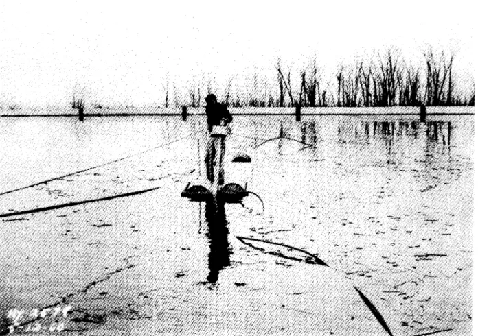
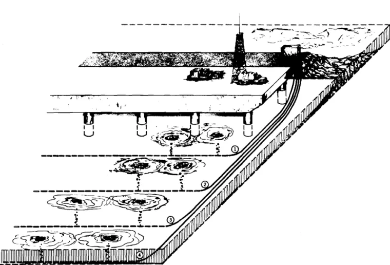
The four units were set in the 400 - by 200 -ft rnano euvr in g basin in the array indicated in Fig. Tセ Figure 5 shows the installation of one 'of
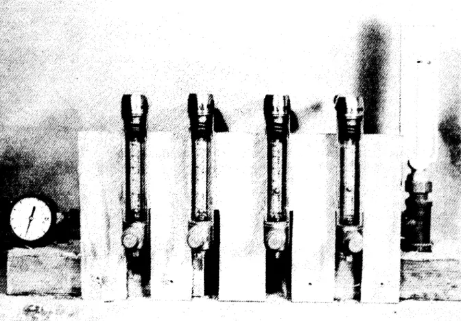
the stackpipe units. Separate 1 -iri , diameter polyethylene pipe connected the units to a compressor housed in a heated building. The air flow was
measured with rotameters (Fig. 6). The outlet pressure from the
compr es sor was maintained at about 20 to 25 psi, but this is only a function of the losses in the system and the desired pressure at the discharge
orifice. The discharge pressure was estimated to be about 2 psi
above hydrostatic pr es sure.
Before the air was turned on, the temperature gradient was
measured at a number of points in the basin with a thermistor thermometer to an accuracy of O.02°e. All points had the same temperature gradient shown in Fig. 7. The ice cover at the start of the experiments (24 Jan.
1961) was 14 in. A 7-in , diameter hole was drilled above each unit
to allow the air to escape. For the first run the air discharge was 0.144
cfrn for all units. This dis char ge was maintained for four days and each day the area of each hole and the ternp e r atur e gradient at various points in the basin were rn e a su r e d, To have a consistent measure of the ice melted by each unit the effective edge of the open water was taken where the ice thickness was 1 in. To calculate the heat losses from the body of water to the atmosphere, records of temperature, humidity and wind were obtained from the Meteorological Service of the Dep a.r trn ent of Transport. For the present discussion, however, they are of no importance since the purpose is to compare various air bubbling systems under identical
conditions. The results of these tests are shown in Fig. 8(a). Although the open areas were still growing after four days, the curves tended to flatten out and a valid co mp a.ris on was possible. F'r o m the point of view of melting ice, the "burper" (unit 2) had a somewhat better efficiency than indicated in Fig. 8(a), as can be judged by the profile of the ice layers
over each hole (Fig. 9). This cross-section also indicates a more effective circulation of the water, in contrast to units 1, 3 and 4, where the wa.ter currents seem to be confined to a thin layer near the surface. It was intended to measure this circulation pattern but the small current meter failed to operate properly in cold water.
The temperature profiles at the end of the experiments at various points in the basin are shown in Figs. 10 and 11. They illustrate
clearly that the mixing has effectively spread over the entire basin. Figure 11 also shows that there must be a heat inflow from the bottom. This is not as clearly discernible near the bubbler units because of the rno r e intense rni xin g in this zone.
The experiments were discontinued and resumed on 6 February with a reduced air flow of 0.072 cfrn an d with the tops of the pipes set 30 in.
The ternp e r atur e profile in the basin before and after these experiments
is shown in Fig. 12. This corroborates the heat recovery from the bottom
and sh ow s the trend toward tke original stratification in Fig. 7. The results of these experiments are shown in Fig. 8(b). Unit No.2 is again conclusively better.
The strange behaviour of unit No. 4 can be explained: This unit was kept in operation between 27 January and 6 February with an air flow of 0.015 cfrn to prevent darna ge to the basin walls due to ice pressure. There was a small open area above unit No.4 when all bubblers were started with 0.072 C£m air flow. Although the area of this original open surface was subtracted when preparing Fig. 8(b), an error here could explain the indicated initial rapid rate of melting. After three days,
however, the effective limit of the hole had been reached. Figure 13 shows the four holes on 10 February.
CONC LUSIONS
A. stated earlier, the scope of the experiments described in this paper was very limited. There are still a great many variables that may influence the efficiency of operation of one unit or another. For
example, the interval between "burp s ", which is dependent upon the rate of flow of air, may have an effect upon the efficiency. The depth below the water surface of the top of the stackpipes may influence the effectiveness of these units. The depth of water is certain to have an effect. Moreover, the units were not operated for a sufficiently long time for the holes to reach their ultimate size. Despite all these recognized limitations, it is believed that the experiments brought out certain facts and raised certain questions which will be useful in future installations.
Under the conditions of these experiments unit No. 2 with the 15 cu in. bubbler outperformed all the other s , It is believed that this is due to the more effective circulation pattern set up. A confirmation of this view should be possible with current meter measurements.
It was also shown that the stackpipe does not contribute, at least in shallow depths, to the effectiveness of the "burper" unit. In fact, it
significantly reduces the efficiency. Moreover, the p e r fo r rnan c e of a simple orifice with stackpipe is practically the same as that of a "burper" with
stackpipe. This was also corroborated by laboratory experiments.
Temperature rne aaur ernent s indicated that the idea of the stackpipe unit drawing the warm water from the bottom and delivering it to the surface without mixing with the intervening layers of colder water is false. The
original temperature stratification is very quickly broken up by the circulation and the temperature gradient in the vicinity of any bubbler installation is zero. There is, of course, despite the 70 -ft spacing, some mutual interference of the bubbler units. This will, however,
manifest itself more in temperature equalization rather than in perceptible curr ents interfering with each other's mechanical action. From this point of view, the effect was welcome since it allowed the comparison of the mechanical action of each unit under identical conditions.
REFERENCES
(l) Williams, G.P. The Thermal Regime of Lakes and Rivers with
Reference to the Use of Air Bubbling Systems. (Included in these Proceedings. )
(2) Baines, W. D. The Principle of the Operation of :aubbling Sy st ern s , (Included in these Proceedings. )
DISCUSSION
Dr. Ince was asked if the ve rti c al temperature gradient was the same throughout the tank at the end of the experiment. If so, did this indicate that one bubbler is influenced by anothe r .
S. INCE replied in the affir rn at iv e , The main purpose of the experiment, however, was to compare bubblers and therefore he cons idered that the interaction between the bubblers for the symmetrical layout used could be ignored for these preliminary observations.
P. F. ANDERSON pointed out that the curves which show the open water area were still rising; this indicated that the maximum area of free water would be larger if the experiment had been continued for a longer time.
S. INCE replied that this was true but that the curves were levelling off and would probably remain in the same relative positions.
A. BERGS asked Dr. Ince if his figures showed a cooling of the water during the winter.
S. INCE confirmed that the water cooled when the bubbler was in operation but that the water temperatures Increased between experiments so that there was very little net heat loss during the winter. He was not sure where the additional heat carne from but thought it possible that it was
L. W. GOLD asked whether the temperature distribution around the bubblers was more favourable for one than for the other.
S. INCE considered that the distribution,after a short period of operation, would be no more favourable for one bubbler than for another.
W. DOTSON reported that on starting the U.S. Navy System at Thule, the initial bubble was about 3 in. in diameter and he asked Dr. Ince if he had observed similar large bubbles.
S. INCE replied that he had seen this effect but was not sure of the size of the initial bubble.
J. N. HINDE inquired about the length of time after the system was shut down were temperatures taken and whether ice formed ove r the holes after the bubbler was shut down.
S. INCE replied that the bubble was open area subsequently froze over. to 25 March.
shut down on 10 February and the Temperatures were measured up
J. N. HINDE inquired if heat from the ground had any effect.
S. INCE replied that he thought it might, but the heat gained fr orr, the underlying bottom material was not measured.
J. N. HINDE suggested that the presence of COt, or some other gas
dissolved in the water might increase the density to a value even greater
than the maximum density at 4° C. This might possibly explain why the
temperature of the water at the bottom was higher than 4° C.
L. W. GOLD asked whether a single bubbler had been used the previous winter and whether this one bubbler had affected the whole tank,
S. INCE replied in the affirmative. The experiments of the past winter
with the four bubblers had been a start in the sorting out of the various factors involved.
J. N. HINDE inquired about the diameter of the stack pipe.
S. INCE said it was 4 in.
P. SHANKS wanted to know how the orifice diameter had been chosen.
S. INCE replied that they tried a 1/32 in. orifice that was too small; a 1/16 in. orifice proved more satisfactory.
J. N. HINDE wanted to know whether the air was oil-free or would include some crank case oil.
S. INCE replied that he used a conventional compressor.
J. N. HINDE said that the conventional compressor was probably
Figure 1 Air bubbler unit No.4. Sirnp l e orifice.
Figure 2 Air bubbler unit No.3.
,1
7°'1,
I
C-20I
70'+
70'L,
,---+
50'l
C-33+
C-38...
FIG.4
200'I
セMMM]
-
= _
MMMセBl-r
SECTION-AAARRANGEMENT OF BUBBLER UNITS
IN THE BASI N
セ ILl ILl LL Z :z: セ 0-ILl o 2 3 4 5 6 7 8 9
TEMPERATURE GRADIENT IN BASII\I
BEFORE AIR BUBBLING EXPERIMENTS
セ セ
---
r----r---r---
r--.
セ
<,
JAN 24 セ\
7.(7'7
FIG.7
o
2 3 44 3 2
o
o
4 3 2o
o
800 800AIR FLOW
I
AI R FLOW0144 cfm 0·072 cfm. 'l. 600
-_._._.
I
600 <t UJ a:: <t )1-UJUJ オセI
--1
II---
t
400I
I
I
T-I
I
I
セ
<t ,400I
LL.UJ 7 a::a:: ::J<t (I)::J a Z(I) UJ c, 0 200 II
,
II
==-..
セ⦅NセMセ 200 TIME-DAYS JAN 24 TO JAN 27 (a) TIME- DAYS FEB 6 TO FEB 9(b)
'1 G) OJICE 4 co
..
·8 セ"
<.l 12>::...
16I
•
I VJ C'o
-.
'''1.
,
tセB
,,
" 0
--:---
_
\.. 080
GMNMMセMZNNNN
_ _ ___._----....
_
セセZZM]RNᆪセCROSS-SECTION OF ICE SHEET OVER EACH BUBBLER UNIT
." G)
TEMPERATURE GRADIENT AT EDGE OF HOLE NO. I
FIG.IO
2 3 4 l0-W W u, z5
:I: I-0.. W o6
7 8 9セ
JAN 27 "fi'?o
23
4FIG. II
TEMPERATURE GRADIENT AT POINTS C-20 AND C-33
9 2 C-33