Construction and Control of Motion Compensation System
ARaIVE
by MASSACHUSEUTS INSTITUTE OF TECHNOLOLGY Teresa GomezAPR 152015
S.B. EngineeringMassachusetts Institute of Technology, 2011
LIBRARIES
SUBMITTED TO THE DEPARTMENT OF MECHANICAL ENGINEERING IN PARTIAL FULFILLMENT OF THE REQUIREMENTS FOR THE DEGREE OF
MASTER OF SCIENCE IN MECHANICAL ENGINEERING
AT THE
MASSACHUSETTS INSTITUTE OF TECHNOLOGY
FEBRUARY 2015
C 2014 Teresa Gomez. All rights reserved.
The author hereby grants to MIT permission to reproduce and to distribute publicly paper and electronic copies of this thesis document in whole or in part
in any medium now known or hereafter created.
Signature of Author:
_Signature
red actedDepartment of Mechanical Engineering October 20, 2014
Signature redacted
Certified by:
Anuradha Annaswamy Senior Pesearch Scientist
T pervisor
Signature
redacted
Accepted by:
David E. Hardt Professor of Mechanical Engineering Graduate Officer
Construction and Control of Motion Compensation System
byTeresa Gomez
Submitted to the Department of Mechanical Engineering on October 20, 2014 in Partial Fulfillment of the Requirements for the Degree of Master of Science in
Mechanical Engineering
ABSTRACT
The rise of technology has put applications such as video filming into the hands of the everyday consumer. With this has come a proliferation of casual camera hardware and self-filmed video. This project concerns the construction of a motion compensation device to augment the video capabilities of casual hardware. It combines facial recognition and tracking, control algorithms, and linear actuation to enable a screen or other object to adapt real-time to the user's head motion.
Unlike other solutions, this system focuses on small, automatic movements based on facial recognition that do not require particularly expensive or specialized equipment to achieve. A webcam is mounted on a moving frame and connected to a primary computer. This device compensates for user motion through physical actuation of this camera, triggered by live analysis of the video feed. The device achieved performance suitable for most envisioned applications. The observed resolution was sufficient to detect and respond to the expected range of movement.
Speed and range of motion were adequate for mild motions, though accurate face tracking was maintained only a few minutes. Without large and vigorous movements, uninterrupted operation could be sustained for that length of time.
Thesis Supervisor: Anuradha Annaswamy Title: Senior Research Scientist
Biographical Note
The author received the degree of Bachelor of Science in Engineering as recommended by the Department of Mechanical Engineering from the Massachusetts Institute of Technology in 2011, concentrating in control, instrumentation, and robotics. She is currently an engineer at Raytheon BBN Technologies.
Acknowledgment
The author would like to recognize the support of her colleagues, friends, and family, with whom all things are possible.
Table of Contents
A b stract ... 2 Biographical N ote ... 3 Acknowledgm ent ... 4 Table of Contents ... 5 L ist o f F ig u res ... 7 L ist o f T ab le s ... 8 Chapter 1: Introduction ... 9 M o tiv atio n ... 9 A p p ro ach ... 9 Current solutions ... 10Chapter sum m ary ... I I Chapter 2: Hardware Description ... 12
2. 1. Device overview ... 12
2.2. M icrocontroller m odule ... 13
2.3. M otion com pensation m odule ... 15
2 .3 . 1 . S erv o ... 16
2.3.2. W ebcam ... 18
2.3.3. Assem bly frame ... 19
2.4. Prim ary computer and display ... 22
Chapter 3: Software ... 24
3. 1. Facial recognition ... 27
3.3. Display features ... 29
Chapter 4: Results ... 32
R e so lu tio n ... 3 2 Range and speed ... 32
Other results ... 33
Chapter 5: Conclusion ... 35
S u m m ary ... 3 5 Future work ... 35
Appendix A : 3D M odels and Drawings ... 37
A .1 3D M odels ... 37
A .2 Drawings ... 40
Appendix B: M ATLAB Code ... 43
B. I M ain function ... 43
B.2 Supporting functions ... 49
B.2.1 Point initialization ... 49
B.2.2 Contrast enhancem ent ... 50
B.2.3 Display window final construction ... 51
B.2.4 Partial face height determ ination ... 52
List of Figures
Figure 1: Inform ation flow diagram ... 12
Figure 2: M icrocontroller m odule... 14
Figure 3: W iring diagram ... 15
Figure 4: M otion com pensation m odule ... 16
Figure 5: Parallax servo ... 17
Figure 6: Philips 61ON C w ebcam ... 19
Figure 7: A ssem bly fram e, inp ... 20
Figure 8: Prim ary com puter screenshot ... 24
Figure 9: Softw are flow chart ... 26
Figure 10: G eneric face im age... 28
Figure 11: Softw are display ... 29
Figure 12: Live w indow , norm al operation ... 30
Figure 13: Live w indow , interrupted operation ... 31
Figure 14: Subassem bly 1 3D m odel... 37
Figure 15: Subassem bly 2 3D m odel... 38
Figure 16: Subassem bly 3 3D m odel... 39
Figure 17: Subassem bly 1 drawing... 40
Figure 18: Subassem bly 2 draw ing... 41
List of Tables
Table 1: BASIC Stamp ® microcontroller properties ... 14
Table 2: Parallax servo properties... 17
Table 3: Philips 61 ONC webcam properties ... 18
Table 4: Assembly frame part inventory ... 21
Table 5: Primary computer specifications ... 23
Table 6: M ATLAB system requirements ... 23
Chapter 1:
Introduction
Motivation
The rise in compact technology has led to a proliferation of portable screens, compact sensors, and customized software applications. With computers in nearly 80 percent of households [29], and a majority of adults owning smartphones [14] [15] on which usage is steadily rising [27],
interest in applications such as video filming is rapidly growing among everyday consumers. This has manifested itself in an explosion of self-filmed video [31] and casual camera hardware.
This thesis explores one concept for augmenting the video capabilities of casual hardware. It introduces a motion compensation device that combines facial recognition and tracking, control algorithms, and actuation to enable a screen or other object to adapt real-time to the user's head motion.
The concept could be used to automatically stabilize an ordinary small camera being used to film a person at close range, or to hoist a smartphone in synchronization with a treadmill user's head motion in order to lessen eye strain and motion-induced nausea. The overall objective is to use the increasingly capable, common, and multipurpose technology available today to enhance the
everyday tasks such technology is used for.
Approach
This device compensates for user motion through physical actuation of the camera, triggered by live analysis of the video feed. A facial recognition algorithm is employed so that the user's head
position within the image frame is the reference from which the necessary motion correction is determined.
In this implementation, a webcam is mounted on a moving frame and connected to a primary computer. This computer runs the main MATLAB code and controls the servo, which hoists the camera. A microcontroller relays commands from the computer to the servo. The range of motion is linear, vertical, and bounded by the dimensions of the frame.
Current solutions
Current motion compensation solutions focus on large linear displacements, such as shooting a camera along a rail for sports coverage [1,6,18] or mounting it on a vehicle for even longer range movement [2]. These are adapted to long movements of relatively constant speed and generally assume horizontal motion.
Some newer solutions utilize a transmitter attached to the user, and rotate the camera towards this tracking tag [19,30]. These systems ignore forgo image analysis and do not provide a live feed to the user, trusting instead that the coarse localization provided by the transmitter is sufficient to keep the user within the frame.
The references cited in this section provide examples of current product types and are not meant to be a complete listing of all commercial brands. Similar offerings may be found from other vendors.
A different solution in development tracks smaller, faster objects using lenses and mirrors rather
than physically moving the camera in order to keep the object of interest in frame [8]. While novel, the physical setup required is elaborate compared to the device outlined here.
This device is instead focused on small, automatic movements based on facial recognition that do not require particularly expensive or specialized equipment to achieve, and can be achieved in a compact space.
Chapter summary
Chapter 2 details the hardware used in this project, encompassing the primary computer and display, microcontroller module, and motion compensation module. The software controlling these components is outlined in Chapter 3, including the facial recognition, feedback control, and display components. Chapter 4 is devoted to an exploration of results and Chapter 5 concludes with a summary and discussion of potential future work for this project. Appendix A provides
3D models and drawings of the device frame, and the MATLAB code of the device is
Chapter 2:
Hardware Description
2.1. Device overview
The physical device consists of three main components: a microcontroller module, a motion compensation module, and a primary computer and display. Software is run on the primary computer and propagates through the system as depicted in Figure 1. Commands from the primary computer are implemented by the microcontroller, which controls the servo. The servo uses the assembly frame to regulate the movement of the webcam, which is directly connected to the primary computer. The live video feed of the webcam provides feedback to the software on the primary computer, which in turn updates the commands to the microcontroller.
The microcontroller module is described in Section 2.2, while the motion compensation module
is described in Section 2.3, and Section 2.4 is devoted to the primary computer and display. Each component is independent and may be controlled by a variety of means. This project
demonstrates just one manifestation of the underlying design, and just one use of the components.
Motion compensation module
Primary computer Microcontroller Assembly frame
and display module
computer Microcontroller Servo Webcam
2.2. Microcontroller module
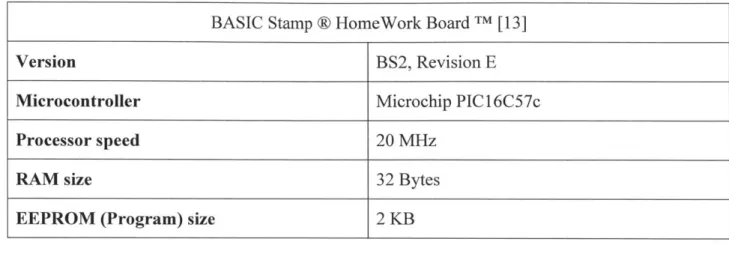
A BASIC Stamp@ HomeWork Board TM by Parallax Inc TM is used to drive the servo of the
motion compensation module. The board connects to the primary computer via an RS-232 serial interface, and to the servo through the built-in breadboard and jumper wires. These wires provide a +5 V DC voltage to the servo as well as a pulse width modulated (PWM) signal generated in
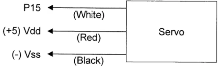
real time on the board by command of the primary computer over the RS-232 interface. Figure 2 depicts the module as configured for this project. The red and blue wires (red and black in the servo leads) transmit the +5 V supply, while the white wires convey the signal. A wiring diagram for this configuration is provided in Figure 3. The entire board is powered by a 9 V Ni-MH battery.
Table 1 lists a few properties of interest regarding the HomeWork Board TM used in this project,
as gathered from the BASIC Stamp Syntax and Reference Manual [13] by Parallax Inc TM. The
microcontroller is being used as little more than a pass-through for the main software on the primary computer, so that the primary computer is able to interact with the servo needed for motion compensation.
Table 1: BASIC Stamp @ microcontroller properties
BASIC Stamp @ HomeWork Board TM [13]
Version BS2, Revision E
Microcontroller Microchip PIC 16C57c
Processor speed 20 MHz
RAM size 32 Bytes
EEPROM (Program) size 2 KB
Servo leads
P1 5 (White)
(+5) Vdd - (Red) Servo
(-) Vss 4 Black)
Figure 3: Wiring diagram
2.3. Motion compensation module
The motion compensation module is the means of actuation and feedback for the system.
Actuation is achieved with a continuous rotation servo, described in Section 2.3.1, translated into linear motion by the plastic block assembly frame. This frame, detailed in Section 2.3.3, serves to adapt the height of a webcam in response to the user's motion. This webcam is described in Section 2.3.2. Figure 4 shows the assembled module from the front, as seen by the user, and from the side to better display the assembly frame.
Front view Side view
Figure 4: Motion compensation module
2.3.1. Servo
The servo is a Parallax Continuous Rotation Servo fitted with a nonstandard horn. Table 2 lists some relevant properties of this servo, as recorded in the Parallax Continuous Servo
Documentation [12]. The torque, size, and power requirements of the servo almost exclusively determine the fundamental limitations of the system, assuming a sufficiently fast processor on which to run the software, making the choice of servo the most accessible way to adjust the motion compensation capabilities of the device. Applications in which the camera to be moved is
of more significant weight, such as one integrated into a smartphone or tablet, or the motion is of particularly high frequency would require a more powerful servo, whereas applications that
value overall portability and endurance would be better suited to a more compact servo. The servo chosen here is depicted in Figure 5.
Table 2: Parallax servo properties
Parallax Continuous Rotation Servo [12]
Torque 38 oz-in (at 6 V)
Dimensions 2.2 x 0.8 x 1.6 in
Voltage requirement 4-6 V DC
Current draw 15-200 mA
Figure 4: Parallax servo
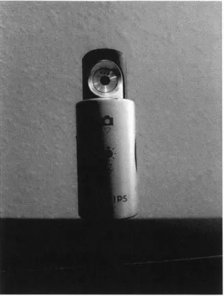
2.3.2. Webcam
The webcam, pictured in Figure 6, is a Philips 61 ONC camera featuring a long, flexible tether and USB interface. While a camera independent of the primary computer is not fundamentally necessary to the system, assuming the primary computer is a sufficiently small computational device, this detached webcam is an especially lightweight option and easily interfaced with the software on the primary computer. Selected properties of the camera from the SPC6 1 ONC User Manual by Philips [16] are listed in Table 3.
It should be noted that while high resolution alternatives are abundant, and would improve the resolution of the system, these are neither necessary nor desirable for this implementation. The exponential increase in pixels slows the image processing performance of the software without yielding practical benefits, as improvements in movement resolution are quickly offset by increased reaction time. Software improvements to increase processing efficiency and utilize greater processing resources could make high resolution video more viable in future
implementations.
Table 3: Philips 61ONC webcam properties
Philips SPC61ONC [16]
Resolution 640 x 480 pixels
Focal ratio F = 2.8
Illumination < 5 lux
Figure 5: Philips 61ONC webcam
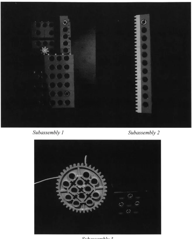
2.3.3. Assembly frame
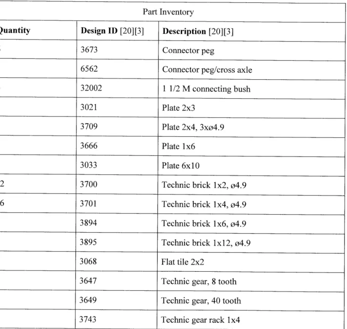
Figure 7 shows the assembly frame expanded into three subassemblies. The first subassembly contains the main structural unit and small gear. The second subassembly is the piece which inserts into the first assembly to convert the rotation of the small gear into linear motion, and which attaches to the webcam described in the previous section. The third subassembly consists of the servo and servo support. The large gear that replaces the standard servo horn connects to and drives the small gear of the first subassembly, which in turn drives the linear motion of the second subassembly and webcam. The gear ratio of 0.2, a shift from a 40 tooth gear to an 8 tooth gear, offers a fivefold improvement in angular velocity but is not used to increase the linear speed of the second subassembly. Instead, the smaller gear is simply an idler gear that constrains and spaces the gear rack.
Subassembly ] Subassembly 2
Subassembly 3
These subassemblies are constructed from LEGO@ Technic parts, which allow modularity and exact replication. A full inventory of the pieces used is provided in Table 4, with the identifiers utilized in the catalog of the manufacturer LEGO* [20] or, for the last three pieces in Table 4 which were unlisted, identifiers found in the BrickLink inventory [3].
Table 4: Assembly frame part inventory
Part Inventory
Quantity Design ID [20][3] Description [20][3]
6 3673 Connector peg
1 6562 Connector peg/cross axle
6 32002 1 1/2 M connecting bush 1 3021 Plate 2x3 1 3709 Plate 2x4, 3xo4.9 1 3666 Plate 1x6 1 3033 Plate 6x10 12 3700 Technic brick 1x2, 04.9
16 3701 Technic brick 1x4, o4.9
6 3894 Technic brick 1x6, o4.9
1 3895 Technic brick Ix 12, 04.9
2 3068 Flat tile 2x2
1 3647 Technic gear, 8 tooth
1 3649 Technic gear, 40 tooth
Appendix A contains detailed 3D models and drawings of all three subassemblies. Drawings are labeled with relevant dimensions.
2.4. Primary computer and display
The primary computer runs the software of the device, in which all image processing and actuation control is performed. This software provides a visual output so that performance may be monitored by the user, should a display be connected to the system. As a display also allows the user to view the command terminal for errors upon startup and unexpected termination, the use of a display is a strongly recommended, but not strictly necessary, addition to normal device operation.
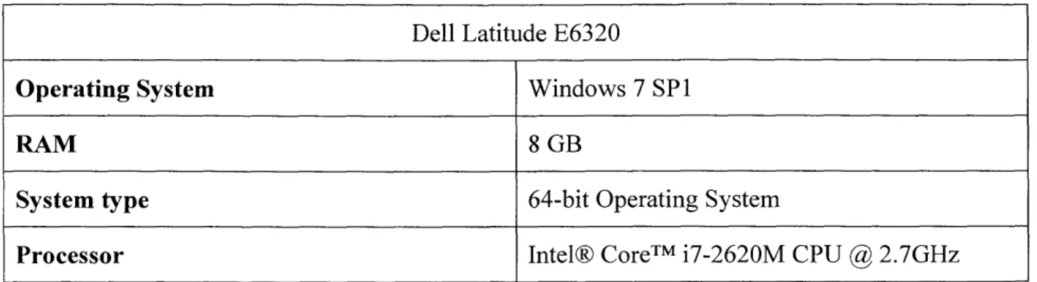
A Dell laptop with the specifications listed in Table 5 serves as the primary computer. The MATLAB software used by the primary computer needs only the system requirements found in Table 6, however, as provided by MathWorks [25]. The primary computer also runs the
MATLAB toolboxes listed in Table 7, which require the same system parameters.
This computer is connected to a 20 inch monitor to display the command window and code as seen in Figure 8. The display used is arbitrary and not integral to running the code, though the display features of the software include a 685x600 pixel window. This 685x600 color pixel display may be considered the minimum display requirement.
Table 5: Primary computer specifications
Dell Latitude E6320
Operating System Windows 7 SPI
RAM 8 GB
System type 64-bit Operating System
Processor Intel® CoreTM i7-2620M CPU
@
2.7GHzTable 6: MATLAB system requirements
System Requirements: Release R2014a [25]
Windows XP, Vista, 7, 8, Server
Operating System Mac OS X 10.7.4+, 10.8, 10.9
Ubuntu 12.04 LTS, 13.04, 13.10, Debian 6.x
Processor Intel or AMD x86 supporting SSE2
Disk Space 3-4 GB recommended
RAM At least 2 GB recommended
Table 7: MATLAB toolboxes
Toolbox Version
Computer Vision System Toolbox [21] 8.1
Image Acquisition Toolbox [23] 9.5
. 1A i4 - n : - T .17-- F1 16 -ntehontnqe 19 - p -20 25 2: facee-etor - 1-inCsaebjc~tco ) 30- sierce -nsnrzercrx a a e e : r 2), 34 - 'Idlo~m J-;ehn':n1 st(ep~aeanet
Figure 6: Primary computer screenshot
Chapter 3:
Software
The software run by the primary computer is written entirely in MATLAB release R2013a, with
the toolboxes previously listed in Table 7. The flowchart overview in Figure 9 shows the main structure of the code.
The software first connects to the microcontroller and webcam. Microcontroller interface related commands were written after reviewing the work of Li et al. [9], who explore the use of
MATLAB to augment the display abilities of the Basic Stamp 2 microcontroller. This device uses unidirectional communication, as feedback is provided to the primary computer through a separate webcam and not the microcontroller. The connection to the webcam is initialized through the Image Acquisition Toolbox from MathWorks [23], which is able to bring control of various camera hardware into the MATLAB development environment.
The Computer Vision System Toolbox from MathWorks [21] is then used to initiate a face tracking algorithm. Facial recognition is discussed in Section 3.1. Both this toolbox and the Image Acquisition Toolbox require the Image Processing Toolbox by MathWorks [24] [26].
The live display window, described in Section 3.3, is the next component to initialize. A
breakdown of the display components may be found there alongside illustration. This window is not essential to the function of the device but provides the means to monitor system performance.
Upon entering normal operation, the software pulls an image from the webcam, enhances the contrast of each color layer, and applies the facial recognition algorithm. It analyzes the new head position and outputs a servo control signal as discussed in Section 3.2 before updating the live display window. Should the image processing fail to recognize the current face, the software will simply clear its parameters and search for a new face while displaying a warning message. This process repeats indefinitely until the program is manually ended from the command window.
This overview is not meant to be a complete description of the software, only a high level look at its structure. The code in its entirety can be found in Appendix B for reference and more
Initialize connections to microcontroller, webcam
Initialize face tracking algorithm
L
C
C
I
a
73
Take frameSearch for current face Yes
Analyze head
Send servo con
Update live displ
trol signal
[
I
ay window Clear curr Ta Searc No mmw Noent face, display
warning
ke frame
h for any face Yes
Figure 7: Software flowchart
Initialize live display window
3.1. Facial recognition
A Kanade-Lucas-Tomasi (KLT) algorithm based face tracker is used for this application [22].
The KLT algorithm tracks inter-frame displacement by minimizing the intensity differences between frames, using a spatial gradient method introduced by Lucas and Kanade [10], with an approach for feature window selection by Tomasi and Kanade [28] and improved feature selection and monitoring by Shi and Tomasi [17].
When a face is located, a set of feature points is identified for tracking. These points, once initialized, can be lost through rapid head movement and view obstruction. As they are not replaced, the software is not able to locate the current face if all tracked points have been lost. In
such a situation, an entirely new set of points, not necessarily on the same face, will be initiated.
The face height is taken to be the center of the feature window identified by the algorithm. This prevents changes in size from triggering motion compensation, so that movement directly toward or away from the webcam and pure rotations are ignored so long as the head remains centered. Should the feature points be reset, the original face height is maintained under the assumption that the original face will be re-identified and that system operation should continue as if uninterrupted.
For privacy reasons, all testing was redone with a generic face printed on a blank background in order to generate the images published herein. No significant drop in performance was observed.
the Digital /Media /Arts curriculum of the Education Development Center, Inc. [5] and colored
with neutral tones.
Figure 8: Generic face image
3.2.
Feedback control
The change in face height as determined through the KLT algorithm is used to decide the actuation signal sent to the servo. Numerous possibilities exist, but given the update rate, a simple proportional control is used. This allows demonstration of system performance while minimizing computational load.
Future implementations with improved computational efficiency and finer height resolution could benefit from more intensive control algorithms. In particular, a predictive algorithm could respond to regular motion and reduce overshoot caused by slow physical reaction speed.
3.3. Display features
The live display window, visible in Figure 11, is generated upon software startup. While the system will operate normally without this window visible, it offers several useful parameter displays.
Figure 9: Software display
Figure 12 provides a breakdown of the display features. These are listed below with fuller description.
Vid..P- Y.X(
~jhtkraPla{_ A. Center point B. Feature points C. Feature window height grp -E. Face to track
Figure 10: Live window, normal operation
A. The center point is the current center of the feature window, and is marked by a green
asterisk.
B. Thefeature points are a set of points to be tracked. Each point moves frame to frame until
lost due to rapid movement or view obstruction, so the number of points decreases over time. Feature points are marked by white crosses.
C. Thefeature window is the bounding box containing feature points. This denotes overall
face position and is represented as a magenta rectangle.
D. The live height graph is a scrolling representation of face height. The horizontal blue line
denotes the initial face height, which is the target height. The green line plots the live face height, showing the error signal over time.
E. Theface to track, in this case, is a generic image used for demonstration purposes.
When all tracking points are lost, the display shown in Figure 13 is experienced. The live height graph is removed, the center point, feature points, and feature window all disappear, and a message is displayed in the middle of the display window until normal operation resumes. Even though the live height graph is not displayed, the initial height has been stored and will be replotted as the blue target height line when the face is rediscovered.
U
Figure 11: Live window, interrupted operation
A video file containing saved display window output is hosted at
web.mit.edu/teremari/Public/Output.avi, for reference and demonstration.
*Video Player MI
Fie Toolis VleN Playbackc Help
Chapter 4:
Results
Resolution
As a 20 cm long face encompassed 200-300 pixels within the image, the system was capable of
0.7-1 mm resolution in face height. Normal adult walking motions produce vertical translations
of approximately 50 mm [11], indicating that sub-millimeter resolution is sufficient to recognize and quantify movement in applications that involve motions similar to walking.
Translations of the face resulting from head tilt, rather than direct lifting from the lower body, are significantly smaller at 5 mm but still readily detectable at the resolution achieved. The displacement value given assumes that the head pitch angle ranges from 0-3 degrees, as is typical during walking activity [11].
Even accounting for large movements away from the camera and differences in user size that shrink the pixel spread of the face of interest by a factor of two or three, the system resolution can be expected to maintain its adequacy for the anticipated uses.
Range and speed
While the range of motion attainable by the device is easily modified by changing the second subassembly of the motion compensation module, the current configuration yielded slightly under 10 cm of potential movement. In practice, to prevent overextension during operation, the range of motion was shortened to 4.6 cm. This is barely sufficient to compensate for walking movements but covers normal head tilt according to the displacement values previously provided.
The maximum linear speed of the webcam was 6.5 mm/s. The theoretical maximum of 10.5 cm/s, given the 4 cm diameter of the gear on the servo horn and 50 rpm maximum of an
unloaded Parallax servo [12], would require weightless and frictionless gears, subassembly parts, and webcam, as well as a control algorithm that constantly applied maximum gain. Nevertheless, the low speed observed is only suitable for slower head tilting and swaying, and not vigorous motion.
Video processing reliably achieved a maximum of 6 frames per second, yielding a reaction time of approximately 170 ms. This frame rate is suitable for capturing low frequency walking and swaying, as vertical translation of the head occurs at approximately 2 Hz [11] in such a situation. The device would not perform well at this frame rate against the vibrations experienced, for example, inside a vehicle where vibration noise significantly exceeds this frequency [7].
Other results
Face tracking was typically maintained for at least 90 seconds, during which time certain motions or lighting would steadily diminish the number of feature points recognized by the tracking algorithm. The loss of these points was not usually due to a sudden single movement or change in lighting so much as gradual, cumulative deterioration. Tracking points were reset after approximately two minutes during runs to maintain accurate determination of face height. Too few tracking points led to the distortion of the feature window that indicates head position.
Other miscellaneous issues include intermittent gear locking and weak coupling of the servo to the support block. These caused occasional stoppages of frame motion, either from sporadic disconnection of the gears or misalignment due to sideways tilting of the servo. Misalignments caused excessive pressure between the gears that impeded or halted the transfer of motion to the gear rack of the second frame subassembly. Both issues were fixable during operation and did not affect performance once addressed.
Chapter
5:
Conclusion
Summary
This thesis describes the construction of a motion compensation system. A primary computer and display, microcontroller module, and motion compensation module combine to hoist a webcam in synchronization with the user's motion. Software running facial recognition and control algorithms, a live display, and optional data output controls the device. Such a system could be used to keep the user's head in frame while filming, or synchronize its motion with an object such as a smartphone screen.
The device performed within limits suitable for most envisioned applications. The observed resolution was sufficient to detect and respond to the expected amplitude of motion. Speed and range of motion were adequate for only mild motions, and the duration of accurate face tracking was roughly two minutes. Barring large and vigorous movements, the device maintained
uninterrupted operation for that length of time.
Future work
Several promising avenues to future improvement present themselves. These are divided between hardware and software improvements.
Hardware improvements include a frame that allows a greater range of motion. A minimum of 5
cm with buffer is needed to compensate for motions comparable to walking [11], indicating that a range of at least 10 cm should be attained. This could be realized by extending the height of the first frame subassembly, lengthening the stem of the second subassembly, providing a wider base
for increased stability, and exchanging the servo for one with greater torque to overcome increased resistance from the webcam tether.
A servo capable of greater torque would also improve the maximum speed of the motion
compensation module, another area of limitation, and compensate for increased friction due to the heavier components.
The most effective software improvements center on processing speed. While some progress could be made through algorithmic efficiency, a more likely route to enhanced performance is simply the advent and usage of better computational hardware. High end products already exist, and if history is any indication, these will rapidly become commonplace.
Appendix A: 3D Models and Drawings
A.1
3D Models
The following models of the motion compensation unit frame were built with SolidWorks® Premium 2013 x64 Edition SP3.0. Part files have been modified from those available through the Carnegie Mellon Robotics Academy website [4].
Figure 13: Subassembly 2 3D model
The gear rack and camera tether are not pictured in Figure 15 as they obstruct the underlying pieces. The gear rack is fixed to the vertical stem of the subassembly while the camera tether threads through the notch in the horizontal top section.
Figure 15: Subassembly 3 3D model
Not pictured in Figure 16 is the Parallax servo, which is fixed to the yellow top of the support block and uses the 40 tooth gear as the servo horn.
A.2 Drawings
The following drawings were also constructed with SolidWorks® Premium 2013 x64 Edition
SP3.0, using the 3D models depicted above. Relevant dimensions are labeled in centimeters.
E ---0 0 ( UlILTh 0SDO 000
0.97 cm
E
000 0
0O
0000J
F04 C 0
=00-I000
OOOOG)
00000
00000
00000
4.84 cm
Figure 16: Subassembly 1 drawing
C UO
U0
QOQO
3.23 cm
E
-I~
L6lcm
4.03 cm
Figure 17: Subassembly 2 drawing
As in Figure 15, the gear rack and camera tether are not pictured in Figure 18 as they obstruct the underlying pieces. The gear rack is fixed to the vertical stem of the subassembly while the
camera tether threads through the notch in the horizontal top section.
0
0-0
0
0
0
0
0
0
0
0
0
0
0
0
E
Ct Vt / '00000
00000
00000
4.3 m
E
UCO
4Figure 18: Subassembly 3 drawing
Again, not pictured in Figure 19 is the Parallax servo, which is fixed to the top of the support block and uses the 40 tooth gear as the servo horn.
3.313mm
E
U
a'-6O
Appendix B: MATLAB Code
B.1 Main function
function TrackFace
- Mster function tc detect fa mrvmn via camera andj . tivate ser
tougm aL ai Itm bocar erved( vertica motion
tic
miD
% zitli e Baic. Stamp Cnne cion bs = stamp.BasicStamp('COM5'); pin = 15; midPoint = 1525; flatLineColor = [0 0 1]; trackLineColor = [0 1 0]; boxColor = '; facePointColor 'w'; centerPointColor = ame rate fps = 6; % itia.Lize .aVii
aviObject = VideoWriter('Output .av i ') ; aviObject.FrameRate = fps;
open(aviObject);
% Initia iz 7jO
cameraObject faceDetector pointTracker
camera concto nd detion tools
= imaq.VideoDevice('winvideo'); = vision.CascadeObjectDetector(;
= vision.PointTracker('MaxBidirectionalError', 2);
%1ni.ialize video feed
videoFrame = enhanceContrast(step(cameraObject));
videoPlayer = vision.VideoPlayer('osition', [100 100 cameraObject.ROI(3:4)+30]); step(videoPlayer, videoFrame);
Detect ace -,x and oots
[facePoints, faceBox] = initializePoints(cameraObject,videoPlayer, faceDetector);
initialize(pointTracker, facePoints, rgb2gray(videoFrame));
oldPoints = facePoints;
visiblePoints = facePoints;
%aG.tainiteal face IIIig .
initialY = mean(faceBox(2:2:end));
Creareimage frame to i running t o O ce heightPi.
AId whita border between vide wlot ant reL ames yFrame(1,:,:) = 1;
% Add line to mark iitial Lace heignt
= findInitialY(size(videoFrame,1),size(yFrame,1),initialY);
yFrame(i,:,:) = repmat(flatLineColor,size(yFrame,2),1);
e arias or r n g hist
faceY = i * ones(1,cameraObject.ROI(3));
servoSig = midPoint * ones(l,cameraObject.ROI(3));
while -isempty(oldPoints)
Redietect race f takingonts have been lost
if isempty(visiblePoints) release(pointTracker);
[facePoints, faceBox] = initializePoints(cameraObject, videoPlayer,faceDetector);
initialize(pointTracker, facePoints, rgb2gray(videoFrame)); oldPoints = facePoints;
% Send vsiabl vs to work sopa
evalin('base',sprintf('faceY = %s;',mat2str(faceY)));
evalin('base',sprintf('servoSig = %s;',mat2str(servoSig))); evalin('base',sprintf('initialY = %s;',num2str(initialY))); end
[facePoints, isFound] = step(pointTracker, rgb2gray(videoFrame)); visiblePoints = facePoints(isFound, :);
oldInliers = oldPoints(isFound, :);
if size(visiblePoints, 1) >= 2
% RPecalate bourning box
[xform,-,visiblePoints] = estimateGeometricTransform( ...
oldInliers,visiblePoints,'similarity','MaxDistance',4);
[faceBox(1:2:end), faceBox(2:2:end)] = transformPointsForward( xform,faceBox(1:2:end),faceBox(2:2:end));
% Overlay boundingabrx ad feat-r onso mg
videoFrame insertShape(videoFrame,'Bolvgon',faceBox,
'Color' ,boxColor);
videoFrame = insertMarker(videoFrame,visiblePoints, ...
'+', 'Color',facePointColor);
Cv& l.ay cenie ... "I"
newFaceX = mean(faceBox(1:2:end));
newFaceY = mean(faceBox(2:2:end));
videoFrame = insertMarker(videoFrame, [newFaceX newFaceY],
'*','Color',centerPointColor);
A sErvo sjpeed .
if newFaceY > initialY
else
newServoSig = midPoint + 21; end
bs.sendPulse(pin,newServoSig);
% Update ~ ovrayfc -v rn egtpo
[videoFrame,yFrame] = insertPlot(videoFrame,yFrame,newFaceY, ... i,flatLineColor,trackLineColor); % g gna.11 h3istory faceY(1:end-1) = faceY(2:end); faceY(end) = cameraObject.ROI(4)-newFaceY; servoSig(1:end-1) = servoSig(2:end); servoSig(end) = newServoSig; oldPoints = visiblePoints; setPoints(pointTracker, oldPoints); end % t ideo rame t v Ie writeVideo(aviObject,videoFrame);
% Pause t0sey rame r at
elapsedTime = toc;
ReLea.se ew frame to vide y
step(videoPlayer, videoFrame);
tic end
%C.ese connecti ns an (. vide- e e close(aviOject); release (cameraObject); release (videoPlayer); release(pointTracker); delete(bs); delete(videoPlayer); end
B.2
Supporting functions
B.2.1 Point initialization
function [facePoints, faceBox] = initializePoints(obj,videoPlayer,
faceDetector)
% t and xort boundg .ox nd it
facePoints = [];
boxPoints = [];
while isempty (facePoints)
% Whi ifCe nc C found
while isempty(boxPoints)
videoFrame = enhanceContrast(step(obj));
videoFrame = insertText(videoFrame,obj.ROI(3:4)/2, ...
'Acquiring target...');
step(videoPlayer, videoFrame);
boxPoints = step(faceDetector, videoFrame); end
%a b nding ... box 'rdiAteS
faceBox = [boxPoints(1,l),boxPoints(1,2),sum(boxPoints(1,[1,3])), boxPoints(1,2),sum(boxPoints(l,[1,3])),sum(boxPoints(1,[2,4])), boxPoints(1,1),sum(boxPoints(1,[2,4]))]; try % -acial - ae s facePoints = detectMinEigenFeatures(rgb2gray(videoFrame), ... 'ROI' ,boxPoints); facePoints = facePoints.Location;
catch
SSt art ovIr if error
facePoints = []; boxPoints = []; continue; end end end
B.2.2 Contrast enhancement
function img = enhanceContrast(img)ciste runction toennane cntrst a o n. each c or 1 layer img(:,:,1) = histeq(img(:,:,1));
img(:,:,2) = histeq(img(:,:,2)); img(:,:,3) = histeq(img(:,:,3)); end
B.2.3 Display window final construction
function [videoFrame,yFrame] = insertPlot(videoFrame,yFrame,newFaceY, ...
i,flatLineColor,trackLineColor)
% Shit cxitingo height lot Lft
yFrame(:,1:end-1,:) = yFrame(:,2:end,:); yFrame(2:end,end,:) = 0; yFrame(i,end,:) flatLineColor; ~ noex ind = round(newFaceY*size(yFrame,1)/size(videoFrame,1)); if nd < 1 ind = 1;
elseif ind > size(yFrame,1) ind = size(yFrame,1);
end
Add new data pointa t Car right yFrame(ind,end,:) = trackLineColor;
% r " 7 lt al otm o tram e
videoFrame(end-size(yFrame,1)+1:end,:,:) = yFrame; end
B.2.4 Partial face height determination
function ind = findInitialY(dimVideo,dimY,initialY) Find app)ropriate pIxeI index
ind = round(initialY*dimY/dimVideo); if ind < 1
ind = 1;
elseif ind > dimY ind = dimY;
end
Bibliography
[1] Aerial Camera Systems. (2014). ACS Ground Tracks. Retrieved September 2014,
from Tracking Camera Systems: http://www.aerialcamerasystems.com/tracking-camera-systems/acs-ground-tracks
[2] Aerial Camera Systems. (2014). Tracking Vehicles. Retrieved September 2014, from
Tracking Camera Systems: http://www.aerialcamerasystems.com/tracking-camera-systems/vehicles
[3] Bricklink Limited. (2014). Brick Link. Retrieved August 2014, from
www.bricklink.com/catalogList.asp
[4] Carnegie Mellon Robotics Academy. (2014). LEGO Solid Modeling. Retrieved
August 2014, from http://www.education.rec.ri.cmu.edu/content/lego/solidmodel
[5] Education Development Center Inc. (2014). Proportion Matters Handout. Retrieved
August 2014, from Digital Media Arts:
http://dma.edc.org/sites/dma.edc.org/files/ProportionMattersHandoutl 1_face.jpg
[6] Glidetrack. (2014). Glidetrack Camera Support Systems. Retrieved September 2014,
from GT Sliders: http://www.glidetrack.com/browse/all/1/0/Sliders/new-additions.html
[7] Gordon, T. J., & Bareket, Z. (2007). Vibration Transmission
from
Road SurfaceFeatures - Vehicle Measurement and Detection. The University of Michigan
Transportation Research Institute.
[8] Heater, B. (2013, June 19). University of Tokyo's fast-tracking camera system could
revolutionize sports coverage. Retrieved September 2014, from Engadget:
http://www.engadget.com/2013/06/19/tracking-system
[9] Li, Y.-F., Harari, S., Wong, H., & Kapila, V. (2004). Matlab-Based Graphical User Interface Development for Basic Stamp 2 Microcontroller Projects. Proceedings of
[10] Lucas, B. D., & Kanade, T. (1981). An Iterative Image Registration Technique with
an Application to Stereo Vision. Proceedings of the Seventh International Joint
Conference on Artificial Intelligence, (pp. 674-679). Vancouver, BC.
[11] Moore, S. T., Hirasaki, E., Raphan, T., & Cohen, B. (2001, October). The Human Vestibulo-Ocular Reflex during Linear Locomotion. Annals of the New York
Academy ofSciences, pp. 139-147.
[12] Parallax Inc. (2011). Parallax Continuous Rotation Servo (#900-00008). Retrieved
August 2014, from http://www.parallax.com/sites/default/files/downloads/900-00008-Continuous-Rotation-Servo-Documentation-v2.2.pdf
[13] Parallax Inc. (2014). BASIC Stamp Syntax and Reference Manual Version 2.2. Retrieved August 2014, from
http://www.parallax.com/sites/default/files/downloads/27218-Web-BASICStampManual-v2.2.pdf
[14] Pew Research Center. (2014). Device Ownership. Retrieved August 2014, from
Media and Technology: http://www.pewresearch.org/data-trend/media-and-technology/device-ownership
[15] Pew Research Center. (2014). Mobile Technology Fact Sheet. Retrieved 2014 August, from Pew Research Internet Project: http://www.pewintemet.org/fact-sheets/mobile-technology-fact-sheet
[16] Philips. (2014). SPC610NC User manual. Retrieved August 2014, from
http://download.p4c.philips.com/files/s/spc610nc_00/spc61 Onc_00_dfueng.pdf
[17] Shi, J., & Tomasi, C. (1994). Good Features to Track. Proceedings of the IEEE
Conference on Computer Vision and Pattern Recognition (pp. 593-600). Seattle, WA:
IEEE.
[18] Shotoku Broadcast Systems. (2014). SmartTrack Rail Camera System. Retrieved September 2014, from Products:
[19] SOLOSHOT Inc. (2014). Retrieved September 2014, from SOLOSHOT Systems:
https://soloshot.com/SHOPLanding-Page
[20] The LEGO Group. (2014). Pick a Brick. Retrieved August 2014, from LEGO:
shop.lego.com/en-US/Pick-A-Brick-ByTheme
[21] The MathWorks, Inc. (2014). Computer Vision System Toolbox. Retrieved August
2014, from Products and Services: http://www.mathworks.com/products/computer-vision
[22] The MathWorks, Inc. (2014). Face Detection and Tracking Using the KLT Algorithm.
Retrieved August 2014, from Documentation Center:
http://www.mathworks.com/help/vision/examples/face-detection-and-tracking-using-the-klt-algorithm.html
[23] The MathWorks, Inc. (2014). Image Acquisition Toolbox. Retrieved August 2014, from Products and Services: http://www.mathworks.com/products/imaq
[24] The MathWorks, Inc. (2014). Image Processing Toolbox. Retrieved August 2014,
from Products and Services: http://www.mathworks.com/products/image
[25] The MathWorks, Inc. (2014). System Requirements -Release R2014a. Retrieved
August 2014, from Product Releases:
http://www.mathworks.com/support/sysreq/currentrelease
[26] The MathWorks, Inc. (2014). System Requirements and Platform Availability. Retrieved August 2014, from Products and Services:
http://www.mathworks.com/products/availability
[27] The Nielsen Company. (2014, July 1). Smartphones: So Many Apps, So Little Time. Retrieved August 2014, from Media and Entertainment:
http://www.nielsen.com/us/en/insights/news/2014/smartphones-so-many-apps--so-much-time.html
[28] Tomasi, C., & Kanade, T. (1991, April). Detection and Tracking of Point Features.
[29] United States Census Bureau. (2012). Computer and Internet Access in the United
States. Retrieved August 2014, from Computer and Internet Use:
http://www.census.gov/hhes/computer/publications/2012.html
[30] Vaddio. (2014). AutoTrak. Retrieved September 2014, from Products: http://www.vaddio.com/category/autotrak
[31] YouTube. (2014). Statistics. Retrieved August 2014, from Press: https://www.youtube.com/yt/press/statistics.html