Crosshole Seismoelectric Measurements in Borehole Models With
Fractures
Zhenya Zhu and M. Nafi Toks¨
oz
Earth Resources Laboratory
Department of Earth, Atmospheric, and Planetary Sciences
Massachusetts Institute of Technology
Cambridge, MA 02139
Abstract
A seismic wave propagating in a fluid-saturated porous media, moves ions in the double layer between the fluid and solid and induces an electric field. When there is discontinuity (such as a fracture), the seismic wave induces a radiating electromagnetic (EM) wave. In this paper, we investigate seismoelectric fields in media with vertical and inclined fractures using cross-borehole measurements in the laboratory. Our laboratory results show that an acoustic source in a borehole generates a radiating EM wave at a vertical fracture, which is recorded by an electrode in the second borehole. The position of the fracture can be determined by the arrival times of the EM wave and acoustic wave, and the velocity of formation. The position of an inclined fracture between two boreholes can be determined by placing the acoustic source at a different depth and recording with real or synthetic arrays of acoustic receivers in the second borehole.
1
Introduction
Seismic waves propagating in a fluid-saturated porous-permeable medium induce fluid motion in the pores (Biot (1956), Mavko and Nur (1979), Berryman (1980), Plona (1982), Bourbie et al. (1987)) In the presence of ions in the fluid, or double charge layer at the fluid-solid interface, the movement of fluid moves the charges and generates an electric field (Morgan et al. (1989), Pride and Haartsen (1996), Pride (1994)). In a homogeneous, porous medium the induced electric field is local and is controlled by rock properties, and by fluid motion driven by the seismic wave (Zhu et al. (2000)). When there is an interface in the medium where properties such as porosity, permeability, and lithology change across the interface, and electrical field discontinuity at the interface gives rise to an electromagnetic (EM) wave radiation (Haartsen (1995), Zhu et al. (1999), Thompson and Gist (1993)). A seismic wave propagation in a geological medium will produce a local electric field in the homogenoues formation, and a radiated EM wave at interfaces between formations. When there is a fracture, the EM radiation is generally stronger than that in the case of formation boundaries. In previous studies of seismoelectric effects of fractures, our studies were directed to cases where fractures intersected a borehole. In the laboratory, Zhu and Toks¨oz (1999) observed EM wave radiation where fractures intersected a borehole. The EM radiation was strong where fractures were normal to borehole axis (i.e. horizontal fracture) and weak for vertical fracture. In a VSP type field experiment, Mikhailov et al. (2000), observed EM waves generated by the incident seismic waves on fractures intersecting the borehole.
In this study, we investigate the seismoelectric signatures of vertical or inclined fractures between two boreholes using cross-hole measurements in the laboratory at ultrasonic frequencies. In these experiments, acoustic sources are placed at a point or in a borehole, and both acoustic and EM waves are reached at the second borehole with the fracture between the source and receiver boreholes. The dependence of electroseismic conversion on fracture properties (aperture, dip) are investigated.
2
Seismoelectric Conversion at a Fracture
To investigate a seismoelectric conversion at a fracture, we conducted a simple experiment, as shown in Figure 1. In this experiment, the acoustic source is a plane transducer mounted on Lucite block. The borehole and acoustic and electrical receivers are in a borehole in a sandstone block. The sandstone is saturated with water. The whole model (shown in Figure 1) is placed in a water tank and the borehole and fracture are filled with water.
P-wave source Hydrophone or Electrode Fracture d 10 cm 5cm 1.27cm Sandstone Lucite
Figure 1: Borehole model with a fracture between sandstone and Lucite blocks. The model is saturated with water. A plane transducer fixes on the Lucite block and generates an acoustic wave. A hydrophone or an electrode moves in the borehole and records the acoustic or electric signals.
The size of the plane transducer is 3.8 cm in diameter. It is excited by a square electric pulse 1000 volts in amplitude and 5 µs in duration. The main acoustic energy focuses in the horizontal direction (Figure 1) due to transition radiation pattern. The widths of the Lucite and the sandstone blocks are 5 cm and 10 cm, respectively. The borehole diameter is 1.27 cm. Receivers consists of a wire electrode and a hydrophone of 1.0 cm in diameter is placed in the water-saturated borehole. It moves along the axis of the borehole.
Figure 2 shows the electric signals (Figure 2a) and the acoustic waves (Figure 2b) recorded in the Lucite-sandstone model with the fracture aperture of 0.5 cm. The amplitudes are normalized. In Figure 2a, the large amplitude electrical signal arriving at 34 µs is due to the acoustic wave impinging on the borehole, generating a tube wave. The tube wave produces the local electric field. The source-to-receiver travel time is that of an acoustic wave. Tn Figure 2a, we also observe an electric signal at about 22 mus. This signal is the electromagnetic wave generated at the fracture by the acoustic wave. The arrival time of this seismoelectric signal is that of the acoustic wave propagating from the source to the sandstone side of the fracture. The EM wave propagation time in the sandstone is negligible (nearly zero).
Figure 2b shows the acoustic signals in the borehole recorded by the hydrophone. The arrival times correspond to acoustic waves from the source traveling through the Lucite, water in the fracture and the sandstone.
To further investigate the seismoelectric signal induced at a fracture, we fixed the acoustic source (the plane transducer) and the electrode in the sandstone borehole in the same horizontal position, and recorded the seismoelectric signals (Figure 3) as we changed the aperture of the fracture. When the aperture increases, the amplitude increases. This increase in amplitude with an increase in aperture means the Stoneley wave converted at the fracture induce the seismoelectric wave due to an increase in the amplitude of the Stoneley
0 0.02 0.04 time (ms) t0=0us, d=0.5cm 5
Electric signal in borehole (1 cm/trace)
(a)
0 0.02 0.04
time (ms) t0=0us, d=0.5cm 5
Acoustic wave in borehole(1.0cm/trace)
(b)
Figure 2: Seismoelectric signal (a) and acoustic wave (b) recorded in the borehole in Figure 1. The amplitude in Figure 2a is normalized for each trace by 200 µV.
wave as the aperture increases. Figure 4 shows the relationship between the aperture and the amplitude of the electric signals.
0 0.02 0.04
time (ms) t0=0us, d=0--8.82mm 5
Electric signal (d: 1.26mm/trace)
Seismoelctric_signal
Figure 3: Seismoelectric signal recorded in a borehole (Figure 1) when the aperture d changes from 0 (trace 1) to 8.82 mm (trace 8) with an increment of 1.26 mm/trace.
From the arrival times of the electric signals in Figure 3, we can calculate the apparent velocity of the arrivals. It is 1500 m/s which is equal to the water velocity. This confirms that the seismoelectric conversion is induced at the sandstone side of the fracture, not at the Lucite side (Zhu et al. (2000)).
3
Vertical Fracture Between Boreholes
Based on the above experiments, we put an acoustic source into a water-filled borehole and conducted crosshole seismoelectric measurements. First, we made a vertical fracture model shown in Figure 5. The
0 5 0 1 0 0 1 5 0 2 0 0 0 2 Amplitude (uV) 4 6 8 1 0 Aperture d (mm) Seismoelectric signals
Figure 4: Relationship between aperture d and amplitude of the seismoelectric signals induced at the fracture and recorded in the borehole (Figure 1).
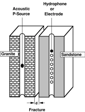
fracture is parallel to the two boreholes. A monopole transducer, as a source, is located in the granite borehole. The transducer made of a PZT tube is 0.9 cm in diameter and 1.2 cm in length, and is excited by an electric pulse 1000 V in amplitude and 5 µs in width. The main energy of this source is in the horizontal direction (Figure 5). Because the size of the tube transducer is small, the acoustic energy is smaller than the plane transducer used in the previous experiment, although the exciting pulse has the same amplitude. The blocks of granite and sandstone in Figure 5 have the same size, 10 cm by 10 cm by 15 cm and boreholes with 1.27 cm in diameter. The fracture aperture is 4 cm.
When the source is fixed at a certain position, we move an electrode or hydrophone in the other borehole to record the seismoelectric and acoustic fields shown in Figures 6a and 6b. The acoustic wave, propagating through granite, water and sandstone at a horizontal direction, arrives at the sandstone borehole at about 60 µs (Figure 6b). In Figure 6a we recorded an electric signal at 45 µs and at 60 µs. Calculating the travel times, we confirm that 45 µs is the arrival time of the acoustic wave propagating from the source to the surface of the sandstone at the fracture. This means that the seismoelectric signal induced by the acoustic wave at the sandstone surface of the fracture is the source of the electromagnetic wave which propagates from the fracture to the sandstone borehole with an EM wave velocity. The first arrivals of the acoustic waves around 60 µs in Figure 6b are slightly different due to different propagating paths. However, it is difficult to see the moveout in the arrival times of the EM waves.
We first determine the arrival time of an acoustic wave in the borehole during crosshole well logging, then determine the seismoelectric wave arriving before that time with crosshole seismoelectric measurements. The fracture position between the borehole can be determined by the arrival time of the EM wave induced at a fracture if the formation velocity is known.
4
Inclined Fracture Between Boreholes
Figure 5 showed a vertical fracture parallel with the boreholes. When the acoustic source is fixed at a certain position, the received EM wave induced at the fracture has the same arrival time in the sandstone borehole. To investigate effect of a dipping fracture between the boreholes, we made a crosshole model shown in Figure 7. The angle between the fracture and horizontal direction is about 70 degrees. A monopole transducer is located in a Lucite borehole, and an electrode is in the sandstone borehole. The aperture of the inclined fracture is 1 cm.
Acoustic P-Source Hydrophone or Electrode Fracture d Granite Sandstone
Figure 5: Crosshole model with a vertical fracture between granite and sandstone blocks. A PZT tube transducer, as an acoustic source, fixes in the granite borehole. A hydrophone or an electrode moves in the sandstone borehole and records an acoustic wave or electric signal.
0 0.05 0.10
time (ms) t0=0us, d=4cm 5
Electric signal in borehole (1 cm/trace)
(a)
0 0.05 0.10
time (ms) t0=0us, d=4cm 5
Acoustic wave in borehole (1 cm/trace)
(b)
Figure 6: Seismoelectric signal (a) and acoustic wave (b) recorded in the sandstone borehole is shown in Figure 5. The amplitude of the electric signals in Figure 6a is normalized by 25 µV for each trace. The aperture is 4 cm.
Acoustic P-Source Hydrophone or Electrode Fracture Lucite Sandstone 1 2 3 4 5 6 7 8 1 2 3 4 5 6 7 8 d=1cm 12 cm
70
o 6cmFigure 7: Crosshole model with an inclined fracture between Lucite and sandstone blocks. An acoustic transducer fixes or moves in the Lucite borehole and generates an acoustic wave. An electrode fixes or moves in the sandstone borehole and records electric signals. The angle between the fracture and the horizontal direction is about 70 degrees. The horizontal distance at #1 from the Lucite borehole to its fracture side is 5 cm and that from the sandstone borehole to its fracture side is 6 cm. The distance between the two boreholes is about 12 cm.
We conducted two experiments to investigate seismoelectric signals induced at the fracture. First, we fixed the source at a certain position in the Lucite borehole, moved the electrode along the sandstone borehole, and recorded electric signals. Then, we fixed the electrode at a certain position in the sandstone borehole and recorded the electric signals when the source moves in the Lucite borehole.
Figure 8 shows the electric signals recorded in the measurements. Figure 8a shows the signal received by the electrode in the sandstone borehole when the source is fixed at position #2 (Figure 7). Figure 8b shows the electric signal received by the electrode fixed at position #2 (Figure 7) in the sandstone borehole when the source moves in the Lucite borehole.
0 0.05 0.10
time (ms) t0=0us, d=1cm, S:#2 5
Electric signal in borehole (1 cm/trace)
(a)
0 0.05 0.10
time (ms) t0=0us, d=1cm, R:#2 5
Electric signal in borehole (1 cm/trace)
(b)
Figure 8: Seismoelectric signals recorded by the electrode in the sandstone borehole (Figure 7): (a) When the source is fixed at position #2 in the Lucite borehole and the electrode moves from position #1 to #8 in the sandstone borehole. The amplitude is normalized by 25 µV. (b) When the source moves from position #1 to #8 in the Lucite borehole and the electrode fixes at position #2 in the sandstone borehole. The amplitude is normalized by 14 µV.
Figure 8a shows electric signals which have the same arrival time at 32 µs when the electrode moves in the sandstone borehole. These signals are radiating seismoelectric signals induced by an acoustic wave at the fracture area corresponding to the horizontal position of the source. The radiating signals propagate with EM wave velocity and arrive at different positions of the sandstone borehole at the same time. After 40 µs, we record stronger signals which have a different arrival time (Figure 8a). For example, the time for trace 8 is 40 µs; for trace 1 it is 48 µs. They are induced on the sandstone borehole wall by acoustic waves propagating through different paths across the fracture and arriving at the borehole. Because the velocities of Lucite and sandstone are different, the arrival times are different.
When the source moves along the borehole with the same increment (1.0 cm in this experiment), the increments of the horizontal distance from the source to the fracture are identical. Therefore, the arrival time of the main acoustic energy from the source to the fracture should be linear. From Figure 8b, before signals with high amplitude, we observe a seismoelectric signal with smaller amplitude whose arrival time is linear. The velocity of the signal is about 2600 m/s from its slope. This velocity is a P-wave velocity of Lucite. From the first arrival (25.5 µs) in trace 1, the fracture aperture (1 cm), and the velocities (2600 m/s in Lucite and 1500 m/s in water), we calculate that the distance at position #1 from the borehole to its fracture side is 4.9 cm, close to the real distance of 5 cm. From the time difference (10.2 µs) between the first arrivals of traces 1 and 8, the vertical distance (7 cm) between traces 1 and 8, and the Lucite velocity (2600 m/s), we calculate that the inclined angle of the fracture is 69.2 degrees. Therefore, if the velocity of the formation between the source borehole and the fracture is known in crosshole seismoelectric measurements, the 2-D fracture position, including distance, dip angle, and direction, can be determined directly from the
radiating seismoelectric signals induced at the fracture.
5
Conclusions
In this paper, we introduced experimental studies of crosshole seismoelectric measurements with a fracture between the source and receiver borehole. When an acoustic source in a borehole generates an acoustic wave, an electrode receives electric signals which are induced by the acoustic wave at a fracture and on the borehole wall.
Our experiments show that seismoelectric conversion at a water-saturated fracture produces a radiating EM wave which can be received at receiver borehole. The fracture location can thus be determined from the arrival times of the EM wave, and the acoustic wave.
If the fracture between the boreholes is inclined, 2-D measurements made by moving the source or the electrode in the boreholes can determine its position, including the distance from the borehole, dip angle, and dip direction.
Crosshole acoustic tomography in boreholes is not sensitive to a single fracture. Compared to crosshole acoustic logging, seismoelectric measurements can directly receive electric signals converted at a fracture, thus determining its position more accurately.
6
Acknowledgements
We would like to thank Dr. Dan Burns and Prof. Frank Dale Morgan for their valuable suggestions and discussions. We also thank Mr. Barry Kirkendall for showing us his results measured in the field. This work was supported by DOE Grant No. DE-FG02-00ER15041 and by the Earth Resources Laboratory Borehole Acoustics and Logging Consortium.
References
Berryman, J. G. (1980). Confirmation of biot’s theory. Appl. Phys. Lett., 37:382–384.
Biot, M. A. (1956). The theory of propagation of elastic waves in fluid-saturated solids: I lower frequency range. J. Acoust. Soc. Am, 28:168–178.
Bourbie, T., Coussy, O., and Zinszner, B. (1987). Acoustics of porous mesia. Editions Technip, Paris, page 324.
Haartsen, M. W. (1995). Coupled electromagnetic and acoustic wavefield modeling in poro-elastic media and its application in geophysical exploration. Ph. D. Thesis, MIT.
Mavko, G. M. and Nur, A. (1979). Wave attenuation in partially saturated rocks. Geophysics, 44:161–178. Mikhailov, O. V., Queen, J., and Toks¨oz, M. N. (2000). Using borehole electroseismic measurements to
detect and characterize fractured (permeable) zone. Geophysics, 65:1098–1112.
Morgan, F. D., Williams, E. R., and Madden, T. R. (1989). Streaming potential properties of westerly granite with applications. Journal of Geophysical Research, 94:12449–12461.
Plona, T. J. (1982). Acoustics of fluid-saturated porous media. Ultrasonic Symp. IEEE, pages 1044–1048. Pride, S. (1994). Govering equations for the coupled electromagnetics and acoustics of porous media. Phys.
Rev. B, 50:15678–15696.
Pride, S. R. and Haartsen, M. W. (1996). Electroseismic wave properties. J. Acoust. Soc. Am., 100:1301– 1315.
Thompson, A. H. and Gist, G. A. (1993). Geophysical applications of electrokinetic conversion. The Leading Edge, 12:1169–1173.
Zhu, Z., Haartsen, M. W., and Toksoz, M. N. (1999). Experimental studies of electrokinetic conversions in fluid-saturated borehole models. Geophysics, 64(5):1349–1356.
Zhu, Z., Haartsen, M. W., and Toks¨oz, M. N. (2000). Experimental studies of seismoelectric conversions in fluid-saturated porous media. Journal of Geophysical Research, 105(B12):28,055–28,064.
Zhu, Z. and Toks¨oz, M. N. (1999). Seismoelectric and seismomagnetic measurements in fractured borehole models. SEG 69th Annual International Meeting Expanded Abstracts, BH/RP 5.7:144–147.