READ THESE TERMS AND CONDITIONS CAREFULLY BEFORE USING THIS WEBSITE. https://nrc-publications.canada.ca/eng/copyright
Vous avez des questions? Nous pouvons vous aider. Pour communiquer directement avec un auteur, consultez la
première page de la revue dans laquelle son article a été publié afin de trouver ses coordonnées. Si vous n’arrivez pas à les repérer, communiquez avec nous à PublicationsArchive-ArchivesPublications@nrc-cnrc.gc.ca.
Questions? Contact the NRC Publications Archive team at
PublicationsArchive-ArchivesPublications@nrc-cnrc.gc.ca. If you wish to email the authors directly, please see the first page of the publication for their contact information.
NRC Publications Archive
Archives des publications du CNRC
This publication could be one of several versions: author’s original, accepted manuscript or the publisher’s version. / La version de cette publication peut être l’une des suivantes : la version prépublication de l’auteur, la version acceptée du manuscrit ou la version de l’éditeur.
Access and use of this website and the material on it are subject to the Terms and Conditions set forth at
Thermal performance of frame walls : Pt. 2 : Air spaces blocked at
mid-height
Handegord, G. O.; Hutcheon, N. B.
https://publications-cnrc.canada.ca/fra/droits
L’accès à ce site Web et l’utilisation de son contenu sont assujettis aux conditions présentées dans le site LISEZ CES CONDITIONS ATTENTIVEMENT AVANT D’UTILISER CE SITE WEB.
NRC Publications Record / Notice d'Archives des publications de CNRC:
https://nrc-publications.canada.ca/eng/view/object/?id=0e5c2bb5-ee5c-4110-b41d-7868c5d226f4 https://publications-cnrc.canada.ca/fra/voir/objet/?id=0e5c2bb5-ee5c-4110-b41d-7868c5d226f4NATIONAL RESEARCH COUNCIL
CANADA
Thermal Performance of Frame Walls
PART I1
Air Spaces Blocked
at
Mid-Height
BY
G.
0 . Handegord and N. B. HuteheonDBR
36
2 3 ~ ~ 2
>Reprint of a paper presented at the Semi-Annual Meeting of The American Society of Heating and Ventilating Engineers, June 29-30, July 1, 1953.
RESEARCH PAPER NO.
10
of the
DIVISION OF BUILDING RESEARCH Ottawa
O U R N A L
S E C T I O N
Therma Performance
of
Frame
Walls
Part I1
-
Air
Spaces Blocked
at
Mid-Height
By
G.
0. Manclegord'i: and N. B. Hlatcheon'i"i:, Saskatoon, Canada
7 ,IIIE FIRST P , ~ P E I ~ ~ presented on this
subjecl dealt with the vertical varia- tions i n tcmperatr~res and hcat flow rates resulting from convection ill a i r spaces in Irame walls. Some of the ~\-alls tested had insulation ideally
applied ~ v h i l e otllers in ~vllich insula-
tion was installed to form t ~ t o air
spaces, had gaps left at the top and bottom. The a i r spaces were con- linuous ovcr the height of the wall. The present paper deals with walls having horizontal blocking at mid- height, and is concer~led. as was the first paper, ~ v i t h the deviations of ac- tual hcat flow and temperature pat-
Lerns [rom those b y simple
~ h e o r y .
Rlocking mag he installed in frame walls to I)rovide nailing g i i t h ~ and acldecl rigidity. When used for ~ h e s e purposes it need not I~lock off the
.iir space completely. It is frec[ucnl-
I!- ~ e q u i r e d . ho~vever. as firestopping
and to 11c effective. must prcscnl a Imrricr to vertical air movement. Walls with complete blocking may h e expected to show two ronvcctiorl patterns over ~ h c i r heiyht.
'rhr effect of through framing incml~crs on overall wall c o n d ~ ~ c t -
ance is usually calculated 11y one o l
two metl~ods given in t h r
H E A T I ~ G .
I \ T I
AIR
CONDITIOUIKG
GUIII~:.
I n the first of these. thewall i s trealed as a series of scp- arate parallel hcat flow paths only,
a n d in he second as a combination
of series a n d parallel patl~s. Neilher of these melhods prooidcs a rational
"Assistant R c e . ~ r c h Officer, Division of Build-
ing Research. National Research Council o f
Canada. J u n i o r Member of ASPE,.
'*Professor of hlechanical B n g ~ n e e r ~ n g . Uni-
versitv of Saskatchea.an. Member of ASHVE.
~ E < ~ o n e n t n u n ~ c r a l s refer to references.
F?r presentation a t the Semi-Annual Meeting
,,t THE A M I ~ R I C A N SOCIT.I.Y or HI~ATING AND
VEXTILATING BNGINEI:~IS, I l e n ~ e r , Colo., June 29-30, July 1, 1953.
SUMMARY-Studies ol' the ther-
mal perl'orn~ance of frame walls
l>reviously reported have beer1 exterirlecl to inclutle an investi- gation ol' the effects prorlueed hy inserting horizontal I>locking
in walls with air spaces. Data
are presented ~vliich illustrate the verticbal variations in tem- peratures and heat flolv rates r e s ~ ~ l t i n g from convectiou within frame walls ~ r i t h blockiag at mid-height w h e ~ l insulatio~l is ideally applied aurl ~ v l ~ e n insu- lation installed to form two air
spaces is in~properly scaled.
Data showing the llorizontal
variation in sl~rface tenlperature
across walls due to the presence of studcling with vzilrio~~s Corms
ol' i~sulation are also given.
I ~ a s i s for calculaiion oI surlace tem- perature under the actual condilions of heat flow in the wall.
The horizontal aurfacc tcinpera-
lure v ~ r i a t i o n ill frame ~ \ ~ a l l s will he
I d ~ g c l j influenred hy the type a n d
. ~ r r a n g e m e ~ ~ t of inst~lalion in the ~vall.
For example, considcralion m a y he
given to the two walls s h o ~ v n in Fig.
1 in which the same insulalion has
heen ir~slalled in laro different posi-
tions. In thc lrrl arrangeinrnt I-a.
[he ouler 1-% in. or ~11c s111ddi11~ i q
r\posed LO air a t a lo~c- trmperatLlre
~ \ h i l e i n the right arrangement 1-1,.
~ h c entire stud is in a region of much
hipher temprralurc. I t would h r cx- pectrd. ~ h e r r f o r e , thal a greater h r a t flow would oc.crlr laterally f r o m thc
stud slio~vn in 1-a than thal ill I-b.
resulting in a lo~vering o l surface temperature in thc area over the slud.
When the vcrtical varia~iolls irl Lcrr~pcr.~lure resulting from ronvcc-
lion a r c also considered, it is see11 that the heat flow is ~ h r e e dirnen- sional a n d thal the correspondilig surface temperature pattern is com-
plex, 1)articularly in walls ~ v i t h block-
ing at mid-height. Since these varia- tions a r c pertinent to any assess- ment of wall performanee, the pres- ent study was extended to ~ ~ r o v i c l e dala on the heat flow and surface temperature pattern at points other
than at the ccnter 01 the stud space.
Tlle project reported here was conductc:cl as part of a program of Cold Weather Wall Research being carried o n cool~cratively h y the Uni-
versily of Saskatchewan and the Di-
vision of Building Ilesearch, Naliol~al Research Council, at Saskatoon.
Test Apparatus
The basic test apparatus employed
lias I ~ e e n dcscril~ed ~ ) r e ~ i o u s l y . ~ Clos-
cr regulation of a i r temperature o n hot11 sidrs of the panel was ohtainccl by the llse of resistance-thr~mometer
bridgc control systems i r ~ place of
those originally used. This change involved no alleration in the air I~eat-
ing syslcm on t h r w a r m side of the
panel. but an intermittenl electrical reheat system was ~trhstituted for the
11yl)ass c1aml)er arrangement for-
merly emploj-ecl in t h c cold room. A second track and carriage was installed on the bamc facing the
warm side of the lest
anel el
oppositea stud location Lo permit simulta- neous heat meter Lraverses vertically ovcr a stud as well as bet~vcen stud- ding. Additional thermocouples wrrc installed to measure wall surface
temperatures o l e r thc slud and 2
in. f r o m the stud at five differen1
hcights. at locatio~ls not immediately
I'reprintcd [ram ASIIVE Jorrrc~nr. S I ( ( . . ~ I ~ I ~ . H c , I ! ~ ; I ~ , Pipinfi G Ah. C o ~ d i t i n ~ ; i n j i
Prirltcd in [J.S.A.
@
J
S E C T I O N
O U R N A L
C O L D S I D E
COLD SIDE
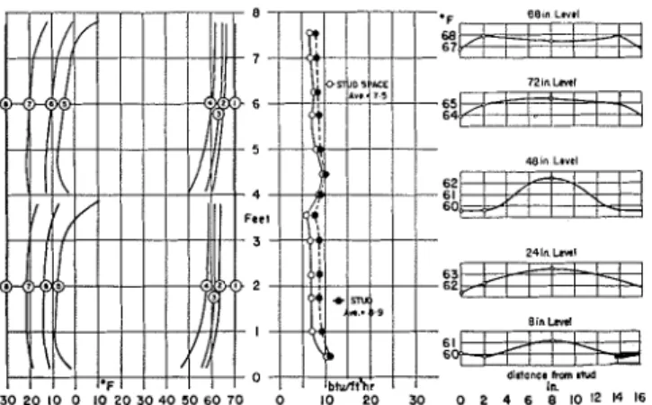
Fig. 1-Two methods of installing batt Fig. 2-Temperature and heat flow variation i n wall No., 2
insulation Single foil curtain creating t w o arr spaces - Foll sealed to surroundiilg
framing members
adiacent to the metal screws L I S C ~ in
construction of the panel.
T h e heatmcters eml~loyed were of thc multiplc differential thermo- couple type, with the sensitive ele- nlcnts mounted betwcen synthetic resin sheets to form a finished metcr
4 4 5 h y 41h- by 3/6.il-in. thick. The
meter used to Lra~erse the wall at the
stud contained two lhermopiles, cach
lncasurinp
:%-
by l l h - i n . spaccdlyq-in. on centers. T h e meter was
orienled with the I l h - i n . dimensiori -
of thc elemcnts horizontal so that no
ort ti on of the t11errnor)iles exte~ldccl heyond the s t t ~ d . The meter usecl to traversc the area at the center of the stud s11ace co~itained lour thcrmo-
piles each measuri~ig
y8-
hy %in.equally spaced, within an area 2- by 2vs-in.
Table 1-Description of Curves
>V d11
1'ar:el Description of Insulation N u m b e r
1 Aluminum foil cemented to cold sur- face of nlasterboard.
2 Single foil curtain crentins t w o air spaces each faced one side with alumi- num foil. Curtain sealed to surround- In@ framinr members
3 ?-in. . enclosed mineral \\roo1 blanket insulation (actual thickness 1%-in.,) creating two air spaces. Dlan- ket sealed to surroundinp framinp mern- hers.
4 ?-in. thick mineral wool hatt insulation placed, next to plasterboard to form one alr space on cold side of insuln- tion.
5 Same as 4 except batt placed ngainst sheathinr. Paper backing sealed to surrounding framing members.
6 Same as 5 except y8'/s- by I-i%-in. strips cut from paper Packing a t hot- tom a n d top of each alr space.
7 Same as 2 with 3/8- by 14%-in. gap at top and bottom of each air space.
8 Same as 3 except blanket stapled but not sealed to s u r r o u n d i n r framinr mem- bers, staples 6-in. apart.
9 Same as 3 with %- by 11'(2-in. g a p at top and bottom of each alr spnce.
Test Prorcclllrc
T h c samc basic ~vall panel. 8-11 in hcight by five standard slut1 spaces in width, was used Ior all tcsts. As in the previous study, only the center three stud spaces were actually em- ployed as test area, the outer two spaces being fully insulated ~ < i t h mincral wool insulation.
T h e test procedure was essentially the samc as f o r the tcsts reported pre- viously. except that cold room air temperatures were maintained at
a more nearly unirorm value. ancl
heatmeter indications were recorded f o r a slightly longer periorl of timc at cach location.
Description of Walls Tested
The basic wall pancl consisted of
:%-in. I~lasterhoard. inside on 2- by
4 i n . (11,$- b y 3v8-in. actual) stud-
ding spaced 16-in. on centers and 25/32- by 10-in. spruce shiplap sheathing. building paper and 6 - by 1h-in. bevel cedar siding on outside. Thc exterior siding and sheathing. and interior plasterboard were se- cured with wood screws and the sicl- ing was given three coats of oil paint. Joints betwee11 framing mcm- bers and sheathing were sealcd with masking tape.
A total of nine different wall con-
structions was studied, each with blocking at mid-height. Only threc different types of insulation were uscd. but variations were introduced in crrtain details of application. The various panels tested a r e clescril)ccl i11
Tahlc 1.
Walls Nos. 1, 2, 4, 5, 6 and 7
Itere similar to walls studied iu thc
previous paper, except for the in-
scrtion of horizontal hlocking at mid- heighl. The paper-el~closed 1)lanket
insulation installed in Walls 3, 8 and
9 was not ~ised in the previous study.
Test Results
Tcst iesults a l e piesented graphi-
call) in Figh. 2 to 10. 'The vertical
variations in t e r n p e r a t ~ ~ i e at various
locations through tlic wall at the cell- tcr linc of the stud space have been plotted at the left h a n d side \vilh the
nuinhering systcm employccl for
identification of the curvcs as s h o ~ n in Tablc 2.
Table 2-Identification of Curves on
Figs. 2-10
Curved
N u m b e r 1.ncation
1 Warm side sir I i n , fr~lrn \\.,~ll surface.
2 W a r m side of plnsterbuard Cold side of plasterboard
2
Air space 3/8 In. Irom plasterhi,;~rd5 Air space 3/8 in. from 511eiitl1ing 6 W a r m side of slienthing
7 Cold side of slleathinr
8 Cold side air 2 in. h n m \\.all s u r f ; ~ r e
-
-
T h e verlical variations in hrat flow rates into the wall at the center- line of the center stud space and at
the stud immediately to the left
havc also I~een plotted for eac11 wall. The val~ies shown were the average of a t least two runs. The heat flow rates given were obtained from ob- served heatmeter millivoltagcs using the conversion data provided by thc manufacturer. without further cali- hration. When the Lraversc of Wall
@ J
S E C T I O N
O U R N A L
Fig. 3-Temperature and heat flow variation in, wall No. 3 Fig. 4-Temperature
T\vo-incli mineral wool blanket insul:ltitrl~, crc-atlng t\vo ;11r s p a c e , scnlecl lnsulatecl \\.it11 t\\,o-inch
to surroun<ling framing mcnibcrs i~~sul:ilion
No. 1 was repeated wilh the ~ w o
meters in~erchanged [lie average per-
centage difference belweeii corre- spondirig readings was found Lo be
\vithiri 2 percent.
Temperatures of ~11c wall surface a t locations over the slud immedi-
ately to the r i g h ~ of the ce~iter of the
wall, 2 in. a ~ ~ d S in. LO the righl 01
this stud are given in Figs. 2 to 10
for five different eleva~io~is. These
measurements were, heref fore. asso-
ciated with the s ~ u d spacc adjacent
to t l ~ a l in which the healmeler data a n d additional Lemperalure measure- rnenls were made.
Precaulions were lake11 LO prevent
entry of waler vapor inlo h e warm roorn eve11 though ambielil cor~cli-
tions oulside in lie laboralory werc
o i the order of 15 percent relalive
h~lrnidity o r lower for rriost of the
test I)criod. r t e r 1110~ection
againsl condensation was protitlcd I)y painling die rold side of the plas- terboard wilh two coats of al~rminum pair11 followed with Lwo coals of
~vliile oil paint. In spile of ~ h e s e
l ~ e c a u t i o n s , some frosling occurred
on ~ l l e shealhing ill all tests.
Heat Flow into Walls with Air Spaces
Thc effecl producetl Ijy inserting
llorizonlal blocking a1 m i d - h e i g h ~
was s u c l ~ as Lo rreale similar palterns
of lernperature a n d heat flow in [lie seclions o i the wall ahove and below
h e blocking. Each o i 111esc. pallerris
was remarkably like those found over
the full height of corresl~onding walls
Iueviously tesled wiltioul blocking.
All l l ~ e walls with air spaces imme-
tliately Lc.hinc1 he plaslerboard
showed ratcs of heal flow inlo he
and heat flow variation i n wall No. 4
~ilincral \\soirl batt - Air spnce un a ~ l d side ot
wall clecreasing with height for each a i r space. This variation was i n keeping will1 the Lemperalure co~~cli- Lions ~ h r o u g h o u l the wall, tempera-
Lures generally increasing with
height f o r each space.
Of he walls in wIiic11 insulation
was ideally applied, those containing
reflective insulation exhibited he
grealest vertical variation in rate of Ileal flow inlo the wall. This feature, more fully discussed i n the previous
paper. car1 Ile allribuled LO the pre-
dominance of the effects of convec- live heill transfer wilh the reducliori in radial11 transfer across the space. The ol~ellings left in the reflective curlain at the lop a n d bottom of
each a i r space in Wall No. 7 in-
creased he average heat flow rate
inlo he area helween studding by 37
percenL over that for Wall No. 2,
I,ut ~11e variation with height was n o t
Fig. 5-Temperature and heat flow variation in wall No. 5 Fig. 6-Temperature and heat flow variation in wall NO. 6
Insulnted wit11 two-inch mineral wool batt - Air space o n warm side of Insulated \\,it11 two-inch r n i n e r ~ l \\,ool bxtt - Air space vn \\,nrm sldr o f
insulntion - B:ltt se:llecl to surrounding framing rnrmbers ii~sulation - C:ll>s '/a in. cut i n paper bncking at t o p and bottom
@
J
S E C T I O N
O U R N A L
Fig. 7-Temperature and heat flow variation in wall No. 7
I r ~ a u l : l t e ~ l nit11 s i n g l e ioil curt;iin c l c ; ~ t i r ~ g tn.u .llr spaces - <;:I[> ~ l i % in.
3t lop :lnd hottum of e:lcll ;lir 5p:Ice
as exlrerne. This rnay parlially Ije ac-
counled for 1)y ~ l l e Sac1 hat conden-
sation had formed on the refleclive
curlain in Wall No. 2 cluring lesl, on
a n area exlending apl)roximalel y 8
in. from the bottom of each air space. This condelisation undoubled- l y affecled the cmissivily of the foil in this region and increasetl 11ie heal flo~v inlo the wall.
Tlie effecls of air-space eonveclion
arc al)parent from a c o m p a r i s o ~ ~ of
heat flow rates inlo the cenler o l ~ l l e
slud space f o r Walls Nos. 3, 8 and 9
in which a milieral wool blankel in-
sulation was iristalled. Wall KO. 9;
i r ~ wl~icli ol~eliings exislcd ~ h r o u g l ~ the insulalion at the bollom and lop
o l eacll air space; showed he greal-
esl vcrlical variation in heal flow of
all he walls tesled, the rate of Ileal
flow irilo 1he wall at he 5-iri. level
being 3 times llle average. I n addi-
Lion the average ralc of heat flow
incrcased by 21 percent of ~ l l a t fo r
Wall-KO. 3 in which the insulation
was sealed in place. When the insu- lalion was slal,Ied, LUL no1 sealed to t h e surrounding framing members.
as in Wall No. 8, only a slighl in-
crease in average Ileal flow over [ha[
l o r Wall No. 3 was ol)served, with
the verlical varialiol~ being somewhal greater.
No significant diflcrellres in 11ier- ~ n a l characterislics were Councl he-
tween Walls Nos.
5
and 6 a l ~ l ~ o u g l ~die insula~iorl was sealed in place irl
Wall No.
5
andv8-
by 14 14-in.openings were cnl tl~l-ough the paper
hacking o l the insulalion at the top
Fig. 8-Ten~perature and heat flow variation in wall No. 8
l l l b ~ ~ l a t e d wit11 t\vo-i11~11 bl;t~llict c r c a t i n g t w o a i r ap;lces -- I3l:lnl;cl bt:~l,lc,l h u t r ~ o t ,c : ~ l c d t u s u l l . c ~ u n < l i ~ ~ g Ir:~r~lin:: lllerl~hers
ant1 bollom o l racll air space in \Val1
No. 6. This closc agree men^ s ~ ~ g g e s l s
Lhal lillle o r no air moveincnl oc- clirrecl h r o u g h tlle insulalion.
r ,
I h e resulk shown hcre, as in ~ h c
previous paper, indicate lllal he lo-
cation of semi-lhick ball-lylje insu-
lalion affects botll he variation in
heat flow wilh height and he average
heal flow rate at ~ l l e cenler of he
slud space. T h e grealcr varialion in
hcat flow vcrticall) ill Wall K O . 5
can be considerctl as clue LO convec-
liorl in he air space hehind he plas-
tcrboard.
The 1)iesence of h i s air spate
rnakes il possil~le Ior heat L O enler at
one poinL and leave a1 some higher
~ ~ o i r l l . I L is equally possible. how-
ever, for heal L O enter llle co~ivective
a i r stream ~ h r o u g l ~ ~ l l e area between
sluds and b e hansporlcd laterally Lo,
and leave by. ~ l l e stud palh. This
can accounl for he higher average
llcal flow I I ~ L I ~ eel1 studs for Wall KO.
5
and is, in fact. sul)porled b y thelo~vcr readings of heal flow inlo the wall opl)ositc slucls. W h e r ~ no air
space is present on ~ l l e warin side of
[he insulation, only lelalively high rcsislanrc palhs to I ~ e a l flow i n the
plane of he wall are ~~roviclecl urllil
thc air space 011 1l1e cold side of he
ir~sult~tion is reachcd. I L Iollo~vs L I I ~
somc. of 1 1 1 ~ heal enlrrs the oulcr
air bljace in Wall No, 4 by way of
thr s t ~ d I ~ a l l l ~ u c l leales tllrough he
ql~eallling bclwcer~ studs.
h l all 11le walls studied. thc vel tical variation in the rale o l heat flow in-
Lo lhc alea over studding ~ v ~ s vcly
similar to he inrialion exisling in
he area belween s ~ u d s . Since such
verlical lalidlions c a n only be at-
lributed LO tlie changc in ail space
lempcralure will1 Iieight, il is obvious
[hat ~ h c lale of heal flo~r inlo s ~ u d -
ding is influenced to a greal exten1
by h e a i r temperature conditions LO
~ r l l i c h h e sides of the stud are eu-
p o s e d This p ~ o v i d e s lur h e r evi-
d e l ~ c e of ~ l l c importance of lateral heat exchange bet\veen studs and air spaces in tlelermining thc overall paltern.
1:ur~hel consideration might I,(,
given Lo coml~drisori of ~ n e a s u ~ e d heat
flow rales into sluddiilg and inlo ~ h c
slud space for the ~ v a l l s ~esled. Sonle
d o u h ~ exisls, Ilo\vc~ er. as LO he cali-
hration correclions L O he applied to
healn~eler readings when tl~erc h a s
1)een a change in tlle a r r a ~ ~ g e r n c n l of
~ n a l e r i a l on which h e heatmeler is p l a ~ e d . Surh coml)arison on a s1ric.L
quanlilalive hasis has, ~hcreforc. been
rcserl ecl until lhese fealurcs of ~ l l e healmclel technique have beer1 evalu-
aled, b u t lherc srems Lo be I I O reason
lo question 1he 01 era11 p a t l e ~ 11 ol heat
flow which the unc.o~rrctecl va111es imply.
Surface T e ~ ~ ~ p e r a t u r e Distril~ntioi~
I~rsicle surface te~nljeralures of es-
terior walls have a clirec~ bec~rirlg or1
solne asl~ects of indoor c o ~ n f o r ~ coii-
ditiotls, 011 thc ~ ~ c , r f o r ~ n i l ~ l c e of pallel
Ilealing sys~cins, OII surlace c o n d e ~ ~ s a -
J
S E C T I O N
O U R N A L
of d i r l pallerns 011 walls. 11 is of somc importance, tl~erefore, Lo nole the very sul>stantial devialions of actual surface tein&~crature palterns from those im1llied by s i n ~ p l e uiii- tlirectional heat flow ~ h e o r y .
Nielser~' has cliscussecl the pro11- leni of dust i r ~ a r k i n g and has shown it to be d u c L O
differences
in rale of ~ ~ c c u m u l a l i o n on adjaccnl areas a1 different Lemperalures. Rogers:' sug- gesls hat a difference of from 3 to5 F deg in wall surface temperatures may 11roduce noliceable dusl palteriis. It may b e noled hat using his crile- rion, Wall No. /Is may exhibit clusl marking over sludding, while all the walls except Nos. 4, 5 a n d 6 may exliibil dust marking just above liori- zor~lal blocking. I t is not correcl,
herel lo re, to assume ~ h a l he appli- calioii of insulation will necessarily
eliminate he tendency to noticeable
dust marking.
Surface condensation will occur whenever the wall surface tempera- Lure falls below he dew 11oint tem- peralure of the air. Poterilial areas for surface conderisation will invari- ably be fourid a t the lower porlion
of a wall. When he wall construc-
tion is such a s to produce a high variation i n surrace temperature verli- cally over the area between sluds the coldest area will tend LO be a1 ~ h c boltom of this vertical zone. When, however, the wall arrangcmeiit is such a s L O produce high heat flow inlo he sluds, he convection cffecls over the ce111er of the space will not bc so marked and the coldest area will be opposite the sludding. T h e effect of
leakage bctweei~ a i r spaces is L O exag- gerate the vertical varialion in s u r - face temperature belwee11 stnds. All
thc walls excepl K O . - b sliow predorni- 11ali11g convective effects and in I I O I I ~ ol' ~ h e s e is the arcu ovcr slucls m a r k - edly coldcr ~ h a n he area I>elwec~n
studs. \-Val1 No. il,, I~owever. 11as
small vertical varialions in surlace tcmpcralure, since he convec:livc eE- fects a r e reslricled to he colcl side of lie iiisulalion. For he same rea- son, the heat flow through he stud- d i n g ~ e r i d s to bc high and lie coldcst a r e a is L O be f o ~ ~ r l d opposite studding.
Wall No. 4: showing he grcalesl
I~orizonlal variation i t 1 surface Lem-
])eralure a t the lower porlion or h e wall does no1 represent the worst 110s- sible case of such varialion. 111 many praclical inslallations, he i ~ ~ s u l a t i o r ~ will not Ile inslalled to fit tightly against he sluds f o r its full ~ h i c k n e s s a n d relatively lower surface temper- alures over studs may b e expected a s a result of the increased heat flow t h r o ~ ~ g h S L U ~ S . T h e most extreme
case known to t h e authors is f o r a form of insulation i ~ o t represented
hcre where leakage exisled a n d the convective effecls combined with high heat flow ~ l i r o u g h he studs to pro- duce, not only Iiig-11 v a r i a l i o ~ ~ s in Leml>erature vertically, but also e r - lreniely low temperatures over studs.
I L may t)c noted that al~llougli Wall No. I exhihiled the crrealcsl hori- 9 zo111al v a r i a l i o ~ ~ it1 surf ace Lempera.
tures over he lower portion of the
wall, Walls Ros. 1, 2, 7 and 9 e r - hibited much lower surIace tempera- tures in this region. The lowest s u r -
face temperature measured at t l ~ e 3- in. level O I I \Vull KO. 9 was 39 F \vhic.11 would pcrmit an inside relati\ e humidity of o r ~ l y 32 percenl a t 70 I:
I ~ e f o r c c o n d c i ~ s a l i o i ~ occurrc~tl. This al)l)lie> Lo t l ~ c test cor~ditions or a n inside to outsitle a i r Lcrnl~e~alure diC- fcrc.ncc or 100
F
cleg wIiic11 al~liou:l~ severe f o r nlosl of 1hc Liniled Slate>. is not unrealislic Eoi he northc.rn part of he conliner~l. All Lests, how- ever, were carried out with room a i r Lemperatures rnai~ilainecl reasoiiahly conslanl ovcr he heighl or the wall. 111 a r ~ ~ t a l praclice some fiiilher low- r r i n g of surface Len~peralures a1 the lower portions of walls rnay r c s u l ~ froni reduced rooin a i r t e ~ n l ~ e r a t u r e s a t floor level or Iroin conlac1 .ivith cold floors or f o u i i d a l i o ~ ~ s . ConclusionsT h e Iollowing c o ~ i c l u s i o ~ ~ s have been d r a w n froiri the tesl results and observations :
1. The heat flow ant1 surface terrlpera- ture patterns i n frame ~ v a l l s a r e greatly
irifluenced l)y lrloverrlellt of 11c.ut ill the
plar~e of the wall.
2 . Su1)stantial rnovernerlt of heat in the plane of a wall occurs largely as a result
of corrvectior~ i n air spaces couplet! r v i t l ~
heat iiiterc:l~ange 11et~vee11 air spaces autl
fraruirlg meml~ers.
3. J'ertical variations i r ~ botl~ ternperature and Ileat flow are related to the convet:- tiorr i r i air spacrs and car1 be rxaggel.atet1
Ily air leakage into or bettvecn air spates.
-1. Horizor~tal variations i r ~ botl~ tempera- ture and heat flow arc 1.elatetl rlot only
to the type but also to the arrangeriient ol' the ruaterial used for i11st1latior1, ar~cl particolarly to the ther~nal resistance pro- vided over the area I)et\veerl studs before
an air space is reached.
Fig. 9-Teniperature and heat flow variation in Wall No. 9 Fig. 10-l'en~perature and heat flow variation in wall NO. 1
I ~ ~ a u l a l r d wit11 two-inch blanket creating two l i r spaces - Gaps of % in. A l l ~ r n i n u n ~ I o i l < e u ~ e ~ ~ t c d ro colil surlnce of p l a ~ l e r board at top and hottom of each air space
O U R N A L
S E C T I O N
5. T h e characteristic pattern of tem- perature and heat I l o ~ ~ r resulting from con- vective effects is not greatly changed by reducing the free height of the air space from 8 f t to 4 f t and in a wall with hori- zontal Idocking a t mid height will be s111)- stantially repeated over each l~locked-oti'
area.
6. Bloc:king a t mid height may prodlice potentially serious conditions for (lust ,
marking in the area irnmediatrly al)ose bloc:king.
7. 'l'he improvement to l ~ e o l ~ t a i n e d throngh the use of insulation, in tendency toward dust marking and surface contlensa-
tion depends not only on the insulation I ~ u t also on the thermal properties of the uverall arrangement crented.
Acknowledgment
The authors ~vish to acknowledge with thanks the assistance give11 them in the taking a n d recording o l data
by other members of the staff of the
Prairie Regional Statioii. Divisiori 01
liuilding Kesearcb. iVa~iorlu1 Rrsec~rclb
Council.
References
1. T h e ~ r n a l Perfo~rndnc.e of Flame Walls, ljy G. 0. I I a n d e g o ~ t l a n d N. R. I-Iutcheon ( A S H V E J o r ' i i \ ~ ~ $1 (-1 lov, I l t ~ ~ t i n g , Piping & Air Cor?ditionirrg, h i a ~ c l ~ , 1952,
11. 1 1 3 ) .
2. l l i ~ t Patterns on Walls, 1,). R. A .
Nielsen (ASHVE T R A \ ? \ ~ rIohs, \'nl. 36,
1940, 1). 247).
3. Design of Insulatetl Bnildings for Various Climates, 1jy T. S. Rogers (F. W.