C-Flow: A Compiler for Statically Scheduled Message
Passing in Parallel Programs
by
Patrick Griffin
Submitted to the Department of Electrical Engineering and Computer Science
in partial fulfillment of the requirements for the degree of
Master of Engineering in Electrical Engineering and Computer Science
aMASSACHUSETS INST"JT
at the OF TECHNOLOGY
MASSACHUSETTS INSTITUTE OF TECHNOLOGY
May 2005 1
Sue 2-dji
@
Patrick Griffin, MMV. All rights reserved.
I
LIBRARIES
The author hereby grants to MIT permission to reproduce and distribute publicly
paper and electronic copies of this thesis document in whole or in part.
/A .
/1
/L
//
A uthor ...
Department of Electrical Engineering and Oomputer Science
May 9, 2005
Certified by ...
A...
Anant Agarwal
Professor
Thesis Supervisor
Accepted by ...
'....
....---
...
Arthur C. Smith
Chairman, Department Committee on Graduate Students
OF TECHNOLOGY
C-Flow: A Compiler for Statically Scheduled Message Passing in Parallel Programs
by
Patrick Griffin
Submitted to the Department of Electrical Engineering and Computer Science on May 9, 2005, in partial fulfillment of the
requirements for the degree of
Master of Engineering in Electrical Engineering and Computer Science
Abstract
Performance improvement in future microprocessors will rely more on the exploitation of parallelism than increases in clock frequency, leading to more multi-core and tiled processor architectures. Despite continuing research into parallelizing compilers, programming mul-tiple instruction stream architectures remains difficult. This document describes C-Flow, a compiler system enabling statically-scheduled message passing between programs running on separate processors.
When combined with statically-scheduled, low-latency networks like those in the MIT Raw processor, C-Flow provides the programmer with a simple but comprehensive mes-saging interface that can be used from high-level languages like C. The use of statically-scheduled messaging allows for fine-grained (single-word) messages that would be quite inefficient in the more traditional message passing systems used in cluster computers. Such fine-grained parallelism is possible because, as in systolic array machines, the network pro-vides all of the necessary synchronization between tiles. On the Raw processor, C-Flow reduces development complexity by allowing the programmer to schedule static messages from a high-level language instead of using assembly code. C-Flow programs have been developed for arrays with 64 or more processor tiles and hve demonstrated performance within twenty percent of hand-optimized assembly.
Thesis Supervisor: Anant Agarwal Title: Professor
Chapter 1
Introduction
Over the last several decades, the rapid development of microelectronics technology has allowed computer architects to design machines with ever-increasing numbers of smaller and faster transistors. In the last few years, though, the ways in which architects can use these resources have changed. While transistors continue to shrink, becoming faster and less power-hungry, the wires that connect them have not scaled as nicely; we are now entering an era in which the cost of sending signals across wires is the predominant factor in determining a microprocessor's speed and power usage. As a result, new architectures have chosen to improve performance through parallelism instead of frequency scaling. Instead of spending silicon resources on ever-larger superscalar machines, architects have begun tiling multiple processors onto a single piece of silicon.
The MIT Raw processor is one such "tiled architecture". Its 16 cores can run 16 separate programs, taking advantage of the thread-level parallelism that Intel and others are pursuing in upcoming chip multiprocessor designs. However, Raw can also connect all 16 cores via a low-latency scalar operand network [1], using all of the distributed resources to work on a single program. Using this approach, Raw can also take advantage of instruction-level parallelism, as well provide excellent performance on stream programs[2].
However, writing programs that take maximum advantage of the scalar operand network requires careful tuning of network communication. Parallelizing compilers do an effective
job of extracting instruction level parallelism, but writing efficient stream programs has
required hand-coded assembly to route data over the operand network. This document describes C-Flow, a system for automatically generating the network routing code needed
Figure 1-1: The Raw Microprocessor (courtesy Jason Miller) Imem Dmem RISC Core Switch
to communicate between Raw tiles. C-Flow allows the programmer to write a simple C program for each tile, specifying any data that should be sent to or received from other tiles. The C-Flow router then generates the necessary routing code, attaining performance on the order of that generated by hand-coded assembly while avoiding the arduous programming process.
1.1
The Raw Processor
The C-Flow compiler chain targets the MIT Raw processor. The Raw processor is composed of 16 symmetrical tiles, arranged into a 4-by-4 grid. Larger grids can be formed by placing multiple Raw chips next to each other, potentially creating grids with 64 or more tiles. Each tile is actually composed of two processors, one for data processing and the other for communication. The following sections describe the data and communication processors that make up each tile; a graphical representation appears in Figure 1.1 and a complete specification of the Raw processor is given in (3].
1.1.1 The Compute Processor
Each Raw tile contains a single-issue, pipelined compute processor. This processor contains a 32-entry register file, integer and floating arithmetic units, and a load/store unit for communicating with main memory. Instruction and data memory caches are also included, each with 32 KB of storage. The compute processor's ISA closely resembles that of a MIPS
RAW Tile
R5000. Thus, from a very high level, Raw could be viewed as a collection of 16 in-order RISC processors placed on the same die.
However, the compute processor does have a few unique characteristics that are useful when parallelizing a program across multiple tiles. Of particular interest is the register-mapped interface to the scalar operand network. Two register numbers, 24 and 26, have been reserved for communicating data to and from the network. Any operation that reads from these registers will pull its operand off of the network via the switch communication processor; similarly, any operation that writes to them will send its output to the switch processor. Thus, reading from and writing to registers 24 or 26 allows the current tile program to communicate with any other tile program via the switch processor.
1.1.2 The Switch Processor
Raw's scalar operand network is implemented as two identical statically-scheduled networks. Arranged in a grid topology, these two "static networks" allow a tile to communicate with its neighbors to the north, south, east, and west. Data words are routed in these four directions, as well as to or from the compute processor, according to an instruction stream running on the switch processor. The switch processor ISA is a 64-bit VLIW form, encoded into two portions: the control flow instruction and the routing instruction.
The switch processor's routing component specifies a data source for each of the possible outgoing ports. For each instruction, the switch processor waits until data is available on all incoming ports that the instruction specifies should be routed to some outgoing port. When all of the needed data is available, the switch processor uses a crossbar to route all of the specified data words in a single cycle, then advances to the next instruction.
The address of that next instruction is determined by the control flow component of the switch VLIW instruction. The control flow component controls a scalar processor which has four registers and is capable of executing branches, jumps, and ops. On a no-op, the switch processor will advance to the next instruction once data routing has been completed; on jump or branch instructions, the next instruction is specified via the control flow instruction component. The scalar control flow processor allows the switch processor to match the control flow on the compute processor. If the control flow is properly matched, the compute processor will sync up with the switch processor, allowing the main tile program to send and receive data as needed via the switch processor controlled static networks.
1.1.3
Comparing Static and Dynamic Networks
Raw's static networks allow separate tiles to communicate with exceptionally low latency, but do so by introducing a new class of networks. Traditional multiprocessor systems have used "dynamically routed networks", in which messages are routed between nodes using information embedded in a "message header". A message header is shipped along with the data words being sent in each message; each time a message arrives at a node, the router examines the header and determines whether the message has arrived at its destination or where the message should be forwarded. Using a dynamic routing scheme allows greater temporal flexibility in routing - because all of the information needed to determine a message's destination is included within the header, the message can be sent at any time. In particular, the routers along a message path need not have any special information in advance of the message's arrival.
In Raw's statically scheduled networks, router circuits are replaced with switch proces-sors. Messages are transmitted across the chip by a sequence of switches; each switch is responsible for moving the message data across a single communication link. Consequently, all switch processors on a message's path must execute an individual instruction to move the message from one link to the next. Thus, the compiler or programmer must know the scheduling of all potential messages in advance in order to schedule the individual routing instructions on the switch processors.
While dynamically routed networks offer greater flexibility, easier scheduling, and sim-ple handling of dynamic events like interrupts, statically scheduled networks offer several advantages for certain classes of applications. First, Raw's statically scheduled networks do not require header words, so no network bandwidth is wasted transmitting extra routing information. Secondly, because all the routing information is specified in the switch pro-cessor's instruction streams, the switch processors can prepare routing operations before the message data actually arrives, allowing for lower message transmission latency. Finally, Raw's static network implementation allows a single data word to be sent to multiple ports, creating a simple mechanism for sending broadcast-type messages. Whereas many dynamic networks would implement broadcasts as multiple messages, one for each recipient, Raw's static network allows a single tile to broadcast to an arbitrary set of recipients with only a single send operation. Thus, static networks sacrifice the ability to handle dynamic events
in exchange for better bandwidth utilization, lower latency, and an easier mechanism for sending messages to multiple recipients. C-Flow allows the programmer to take advantage of these network characteristics without having to program the individual switch processors.
1.2
Related Work
At present, there a several methods by which a programmer can generate the compute and switch processor code needed to execute a program on Raw. These methods include RawCC, a parallelizing compiler that generates multiple tile programs from a single sequential C program, StreamIt, a language for specifying linear filter-based programs, and hand coding. These mechanisms have been used to show that Raw provides performance that ranges from comparable to orders of magnitude better than that of a Pentium 3 implemented on the same process[2].
Parallelizing compilers like RawCC [4] and the IMPACT-based [5] RepTile present the most familiar interface for programming Raw. These compiler tools take a single sequen-tial C-language program as input and transform it into separate programs for each tile. The tile programs communicate via the static network; by working together, Raw's 16 tiles can contribute their execution resources to completing a single program. While our par-allelizing compiler tools have successfully compiled many SpecInt benchmarks, these tools remain rather fragile. Using them requires careful attention to the compiler environment, and proper compilation is not guaranteed. Additionally, these tools provide adequate per-formance only when used to extract instruction-level parallelism. If a program can been structured as a stream of data flowing through filters, other programming methods can achieve much higher performance.
The high-level StreamIt language has been developed for programs that do fit this "streaming" model [6]. StreamIt programs are specified as a set of filters operating on streams of data. This compiler system provides an exceptionally clear method for program-ming linear filters. Even better, the performance of its generated programs has been equal to that of hand-coded programs in several cases. However, StreamIt is only useful for pro-grams that can be described as linear filters. Many propro-grams do not fit into this paradigm; for instance, algorithms that make use of pointer-based data structures (graphs, trees, etc.) are not a good match for StreamIt.
coded programs offer the best potential for performance optimization. Hand-coding requires writing tile programs in C or assembly. The routing code for the switch processor must be written in assembly. The later task can be particularly arduous, as it requires careful attention to synchronization and deadlock avoidance. However, in cases where the programmer has a clear idea of how the program should be partitioned across Raw's tiles, hand coding is the clear performance winner. Hand-coded streaming algorithms have shown remarkable scaling properties, in some cases actually improving their percentage resource utilization as the number of tiles is increased [7].
C-Flow seeks to provide the flexibility of coding without the necessity of hand-written switch assembly code. Our implementation allows the programmer to write C code for each tile. The switch code necessary for communication between these tile programs is automatically generated by the C-Flow compiler. By generating switch code automatically, Flow simplifies the process of writing manually partitioned Raw programs. Thus, C-Flow's switch code generation facility allows the programmer to write larger programs more quickly, while maintaining performance similar to that of a program with hand-coded switch instructions.
The C-Flow programming interface has a certain similarity to the message passing inter-faces frequently used in parallel and distributed computing. The MPI messaging interface [8]
is frequently used in large cluster machines and is optimized for bulk data transfers. The single-word sized messages used in C-Flow would be very inefficient when used with such systems. Hardware message-passing machines, like the MIT Alewife system [9], are more capable of fine-grained messaging but still perform dynamic routing and scheduling, unlike C-Flow's statically scheduled messaging.
Chapter 2
An Overview of C-Flow
C-Flow allows the programmer to describe an application as a set of tile programs, each written in C. These tile programs, referred to as 'strands', can include communication operations that provide a basic form of message passing. Each strand can "send" or "receive" single data words to or from any other strand. The C-Flow compiler uses static analysis tools to automatically generate static network message schedules, unifying the separate "strands" into a single multi-tile "program". This chapter has two sections: the first describes the language interface used to access C-Flow from within C code and the second gives an overview of the C-Flow compiler system.
2.1
The C-Flow Programming Interface
C-Flow provides the application programmer with an MPI-like interface for sending mes-sages between "strands". Each strand is composed of C-language code assigned to run on a particular tile or port. Strands can communicate with each other by sending messages across "channels". Channels are defined as global variables at the beginning of each C source file, and communication operations within function bodies send particular data words across these channels. This section defines the types of channels, the messaging operations, and the coding conventions that are used within C-Flow programs.
2.1.1 Endpoints and Groups
C-Flow allows two types of channels: endpoint channels and group channels. Endpoint channels are useful for point-to-point communication; they allow a strand to define some
Command Argument Argument Purpose cf-endpoint x a tile's x coordinate
y a tile's y coordinate cf-port-endpoint x a tile's x coordinate
y a tile's y coordinate
dir direction of port from tile ('N', 'S', 'W', 'E')
cf-rel-endpoint x offset in x direction from current tile
y offset in y direction from current tile Table 2.1: Commands for Defining Communication Endpoints
distant target to which words of data may be sent. Group channels, on the other hand, define some set of strands which will perform a certain operation. For example, group channels are useful for broadcasts (one-to-many communication) and barriers.
While all channels are defined as global data at the beginning of a source file, there are several different methods for defining a channel. The mechanisms for defining endpoint channels are listed in Table 2.1. The basic cf.endpoint(x, y) form defines a channel between the current strand and the strand running on tile (x, y).
Many C-Flow applications stream data on and off chip via Raw's external static network ports. In order to allow such communication, C-Flow allows the programmer to create "port" strands, pieces of code that generate the communication patterns that will occur on the static network port. Essentially, the programmer defines messages going to and from ports by creating a strand that would run on the opposite side of the port. Of course, when the final C-Flow compiled program is executed, there is no such tile on the opposite edge of the port, but the messages will go to and from the port as if there were. Consequently, when writing a "port strand", the programmer need only worry about the order of messages going to and from the port, not the values of the data being transmitted.
The other two endpoint definition mechanisms shown in Table 2.1 allow the programmer to define channels between tile strands and port strands. The cf-port-endpoint(x, y, dir) form defines a channel between the current strand and the "port strand" running on the specified port. The most general endpoint channel definition is cf-relendpoint, which defines a channel between the current strand and the strand located an offset of (x, y) from the current strand's location. If the offset defines a strand running off the edge of the grid, the channel is declared as communicating with the port adjacent to that off-chip location.
Command Argument Argument Purpose
cf.group..member label the name of the group containing this strand
Table 2.2: Commands for Defining Group Membership
group. The cf-group.member("name") macro, seen in Table 2.2, provides the mechanism for declaring group membership. The group "somename" is defined as the set of all strands which contain a cf-group..member("somename") declaration. A group may be composed of just two tiles, every strand in the program (ports and tiles), or any other arbitrary set of strands.
2.1.2 Communication Commands
Once a strand has declared communication channels, it can use C-Flow's messaging func-tions to communicate with other strands. Table 2.1.2 shows the various communication functions provided by C-Flow. Simple point-to-point communication is handled by the
cf..send(value, endpoint, "label") and value = cf..receive(endpoint, "label") functions.
C-Flow uses static analysis tools to match send and receive pairs on different strands while guaranteeing deadlock avoidance.
Group channels are used for two types of messaging: broadcasts and barriers. The
cfbroad.send(value, group, "label") and value = cfJbroadLreceive (group, "label") functions
are used to perform broadcast operations. The group specified in each of these commands is the set of all strands involved in the broadcast; i.e. the sending strand plus all receiving strands. The cf-barrier(group, "label") function provides a synchronization primitive; all strands in 'group' will wait at the barrier until every member of 'group' has arrived at the barrier.
All C-Flow communication commands take an optional "label" argument. This string
provides a simple form of type-checking; when the C-Flow compiler's static analysis tools recognize a send/receive pair, they check that the labels match. This mechanism is useful for avoiding message ordering bugs; if tile 0 sends ("a", "b") but tile 1 receives ("b", "a"), a warning will be generated.
Command Argument Argument Purpose
cf-send value data word to be transmitted
endpoint strand that will receive the message label a string identifying this message cf-receive endpoint strand that sent the message
label a string identifying the message cf-broad-send value data word to be transmitted
group set of strands that will receive the message label a string identifying this message
cf-broad-receive group set of strands receiving broadcast label a string identifying the message cf-barrier group set of tiles to synchronize
label a string identifying this synchronization point Table 2.3: Commands for Sending and Receiving Data
2.1.3 An Example Program: Chroma-Keying
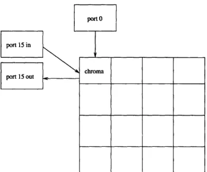
In order to demonstrate the capabilities of C-Flow, this section provides a simple example program. This "chroma-keying" application accepts two incoming data streams from ports
0 and 15. The main strand, running on tile 0, examines the two input streams, and if a
pixel in one of them is green, it is replaced with a pixel from the other stream. The result is then sent out of the chip via port 15. The end result is the green-screen effect used to place TV weathermen in front of maps.
Figure 2-1 show a graphical representation of the various strands involved in the chroma-keying application. The source files for each strand appear in Figures 2-2, 2-3, 2-4, and 2-5. The main program, and the only code that actually executes on Raw, is shown in Figure 2-2. This tile strand receives two input pixels, one from the camera and the other from a background image. If the camera pixel is green, the tile strand substitutes the background image pixel value and sends the result to the output port.
The astute observer will notice that this C-Flow application has three port strands but only two port locations: ports 0 and 15. This is possible because there is no control flow coupling between the incoming and outgoing buses on a particular port. Put another way, there is no switch processor on the opposite side of an external port, so there is no instruction stream governing when words cross the incoming and outgoing buses. Thus, C-Flow allows the assignment of Figure 2-4 to port 15's incoming bus and the assignment of Figure 2-5 to port 15's outgoing bus. Port 0, by contrast, has only one strand, shown in Figure 2-3. By allowing the programmer to assign separate strands to the incoming and
port 0
port 15 in
chroma port 15 out
Figure 2-1: Chroma Keying Strand Assignment
outgoing buses on a particular port, C-Flow decouples incoming and outgoing messages. This decoupling may allow for more optimal scheduling of messages because, for instance, incoming messages need not necessarily wait for some outgoing result to be computed.
2.1.4 Matched Control Flow Depth
C-Flow uses static analysis tools to determine the ordering of communication operations between tiles. Given a set of strands as input, the C-Flow compiler uses basic-block analysis to extract the per-function control flow for each strand. In order to schedule a message between two strands, the C-Flow compiler must be able to guarantee that the receiving tile will be waiting when the sending tile sends its data word; if this is not the case, the system will deadlock as unreceived data words block up the static network.
Guaranteeing send/receive pairings requires that C-Flow be able to match up the control flow on the sending and receiving tiles. Our chroma-keying example satisfies this require-ment. All of the input strand source files are composed of an infinite loop containing some messaging function calls. By examining the ordering of the sends and receives within the
four main loop bodies, C-Flow will determine that each loop consists of three messages:
(port 0, tile 0), (port 15, tile 0), and (tile 0, port 15). Thus, the number of loop iterations is the same for all communicating strands, and the ordering of communication commands
//chroma-tile.c
cLendpoint port15 = cLport-endpoint(0,0,'W'); cLendpoint portO = cLport-endpoint(0,0,'N');
void begino {
long blue, sub;
long r,g,b;
long result; 10
for(;;){
blue = cf-receive(portl5, "blue_ in");
sub = cf-receive(portO," sub- in");
b = blue & MASK;
r = (blue >> RED-SHIFT) & MASK;
g = (blue >> GREEN-SHIFT) & MASK;
20
if(((b > BLUE-LO) && (b < BLUEHI)) && ((r > RED-LO) && (r < RED.HI)) &&
((g > GREENLO) && (g < GREENHI))
){
result = sub;
}
else {
result = blue;
}
cLsend(result, portO, "result"); 30
}
}
//portO.c
cLendpoint tileO = cLtile.endpoint(0,0);
void begin()
{
for(;;){
int
trash = Oxdeadbeef;cf.send(trash,
tileO, "subin");}
}
Figure 2-3: Chroma data coming from port 0
//portl5_send.c
cLendpoint tile0 = cLtile-endpoint(0,0); void begin(
{
int trash = Oxcfcfcfcf;
cLsend(trash, tile0, "blue-in");
}
}
Figure 2-4: Chroma data coming from port 15
//port15_receive.c
cEendpoint tileO = cLtile-endpoint(0,0); void begin( { for(;;){ cLreceive(tileO, "result");
}
}
Figure 2-5: Chroma results going to port 15
10
10
within the loop body matches up to form a sequence of send/receive pairs, so C-Flow can determine the overall message schedule and generate the corresponding switch code.
In order to match send and receive operations in two different strands, C-Flow requires that those two communication operations have the same control-flow nesting. That is, if strand A sends a word to strand B, and the "send" operation is inside of two nested loops, the "receive" operation in strand B must also be nested inside two loops. Thus, any control flow primitive (loop, if/else if/if block, switch statement) that surrounds a communication operation must appear on both strands involved in sending and receiving that message. Effectively, the control flow hierarchy must be the same in all communicating strands. Of course, control flow that is localized to only one tile, i.e. does not contain any sends or receives, need only appear on the tile that uses that control flow. Thus, in our chroma example, all of the strands must have their communication operations inside of the same infinite loop, but the main strand is the only strand with an "if/else if" block inside the body of that infinite loop. The C-Flow compiler requires that the communication operations
appear in the body of the infinite loop, but it ignores any nested control flow that does not affect the communication schedule.
C-Flow's requirement of matching control depth means that some intuitively possible programs cannot be compiled by C-Flow. For example, Figure 2-6 shows a strand with two similar loops embedded in either half of an if/else block. Figure 2-7 shows a strand with a loop that, intuitively, would match up with either loop body. Essentially, the message schedule does not depend on the if/else block; regardless of the evaluation of the if statement, the message schedule will always consist of 10 messages from tile0 to tilel. However, C-Flow cannot compile and match up the message schedules in this program because it requires that the hierarchy of control flow be the same on both sides of a send/receive pair. Thus, in order to compile with C-Flow, this program would have to be changed so that tile 1 includes the if statement that exists on tile 0. The requirement of matching control flow hierarchy can be tricky, but in our experience it does not limit the types of algorithms that may be compiled with C-Flow.
2.1.5 Function Calls
C-Flow allows the programmer to make subroutine calls in order to encourage source code modularity. However, whenever a particular strand calls a function, C-Flow must guarantee
#include "raw.h" #include "cflow.h" tilel = cLtile...endpoint(0,1); void begin( { int num; int i; 10
}
if(num < 5){ for(i = 0; i < 10; i++)cLsend(i, tilel, "count");
}
else {
for(i = 0; i < 10; i++)
cf-send(10
- i, tilel, "count"); }20
Figure 2-6: Loops nested within an if statement
#include "raw.h" #include "cflow.h" tileO = cLtile..endpoint(0,0); void begin() { int num; int i; 10 for(i = 0; i < 10; i++)
num = cLreceive(tileO, "count");
Figure 2-7: A matching loop that will not merge
that all other strands that use that function make the call at the same time. If this guarantee failed, a tile could call a function, attempt to send a message, and hang because the message recipient had not made an equivalent function call.
In order to guarantee that functions are only called when all of their communication partners call the same function, C-Flow performs a series of tests at compile time. First, all functions with the same name are assigned to a "group function". Thus, if tiles 0, 1, and 2 all contain a function named "foo", the group function "foo" operates on the set (tile 0, tile 1, tile 2).
Having determined all of a program's "group functions", C-Flow checks to be sure that each group function satisfies several properties. First, if a group function 'A' is called by a group function 'B', the strands in 'A' must be a subset of those in 'B'. Secondly, C-Flow verifies that all communication operations within a group function operate only on strands that are member of that group function. Thus, a group function containing tiles 1, 2, and
3 may only communicate amongst those three tiles, it may not communicate with tile 4.
Finally, when checking that the control flow hierarchy matches between strands, C-Flow verifies that any call to a group function happens at the same control flow point in all of the group function's strands. These verification steps will be explained in greater detail in Chapter 4, which describes the process of merging separate strands into a single unified program.
The only exception to the above rules is for functions from external libraries or functions which do not call any messaging commands. These functions will not send or receive any messages, so C-Flow can be assured that they will not result in a network deadlock condition. Allowing communication-free function calls without performing the group function checks is particularly important for library routines such as 'malloc'. Malloco may be called on many tiles, and since it has the same name on all tiles, it would initially be marked as a group function. However, since malloco does not use any communication operations, the group checks are not performed and strands may allocate memory independently of each other.
2.2
An Overview of the C-Flow Compiler
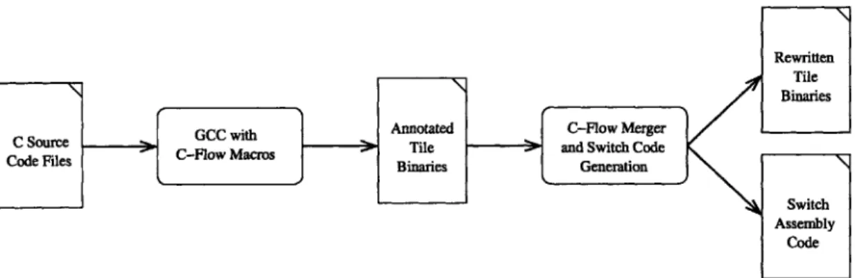
The C-Flow compilation infrastructure takes input in the form of C-language source code, analyzes the per-tile programs to determine messaging patterns, and generates the switch code necessary to schedule the program's messages. A graphical representation of the toolchain appears in Figure 2.2. The toolchain was designed to maximize code reuse; to that end, GCC and the Raw project's binary rewriting infrastructure play a significant role in compiling C-Flow programs. The next paragraphs will describe each of the compilation stages in detail.
A C-Flow application starts as a collection of C-language source files. Each source
file may or may not contain some C-Flow directives. As specified in Section 2.1, there are two types of directives: channel definitions and communication commands. Channel declarations are used to assign a name to a particular communication route that will be used by communications commands.
The first stage of the compilation process uses the Raw project's GCC compiler to transform the C-language source code into a binary for each tile. The output binaries are instrumented with C-Flow commands and data so that later compilation stages can deter-mine the messaging pattern between different tile programs. C-Flow channel declarations and communication commands are both inserted into the output binaries by a set of C preprocessor macros that are included in the C-Flow header file.
Channel declarations are stored as data words in the binaries' data segment; each word contains 4 bytes, indicating the x and y coordinates at the far end of the channel (the near end of the channel is implicitly the tile being compiled for), the type of the far end (tile or external port), and the off-chip routing direction for external port endpoints. Storing the channel information in the data segment allows the C-Flow macro routines to take advantage of gcc's C preprocessor. As a result, the arguments to a channel declaration may be either expressions or constants; this feature is particularly useful when using C macros to define several different strands within one source file. For example, certain channels could be declared only when the source file is compiled as a "port strand".
Communication commands are stored as 'move to static network port' instructions in the binaries' code segment. Each communication command in the code segment also has a corresponding annotation in a special "notes" segment added to the Raw binary format
Rewritten Tile Binaries
Fiure 2:Annotated C-Flow Merger
C Source C-F'owuc file l-enme> Tile and Switch Cwdoden
Aod es pBinaries Generation
Switch Assembly
Code
Figure 2-8: The C-Flow Compilation Toolchain
to help support C-Flow. By matching a communication instruction in the code segment with an annotation in the notes segment, later compilation stages can determine which communication channel is being used by each communication instruction. In addition to the communication channel name, annotations also include useful debugging information such as the command's source file line number and an optional name for each word sent.
All of the per-tile annotated binaries generated by GCC are used as the input to the
next stage of the C-Flow toolchain, the merging and scheduling compiler. This stage in the toolchain has two phases. The first stage, described in Chapter 3, reconstructs the control-flow and message commands on a per-strand basis. The second stage, described in Chapter 4, merges the per-strand control flow into a single program, then schedules and routes each message operation. After both phases ae complete, the output is stored as rewritten binaries for each tile and assembly code for each static switch. The rewritten binaries and switch assembly are then ready for assembly into a Raw boot image via the Raw project's standard assembler and linker tools.
2.3
Summary
This chapter has introduced the Flow language interface and compiler system. A
C-Flow program is composed of several "strand" programs, each of which represent either
computation and communication taking place on a tile or communication occuring across an external port. Each strand may contain two types of Flow primitives with its C-language code: communication operations and channel declarations. By matching the send and receive operations in different strands while guaranteeing that those strands contain the
same loop and conditional structures, the C-Flow compiler can determine a unique message schedule for the program as a whole. The next two chapters describe the process by which C-Flow rebuilds each strand's control flow and merges the strands into a single program.
Chapter 3
Extracting Control Flow from
Object Files
As described in Section 2.2, each strand in a C-Flow program is passed to the compiler as an object file. The compiler is responsible for extracting the message schedule from the input strands and generating the switch code needed to execute that message schedule. The C-Flow compiler accomplishes this job in two phases. First, it converts the object file back into a structured program made up of loops, if/else statements, and compound conditionals. These control flow elements may be nested, forming a control flow hierarchy. The compiler takes each strand binary and extracts the control flow hierarchy that was originally in the
C source for that strand. Once each strand's control flow hierarchy has been reconstructed,
the compiler moves on to stage two, merging the separate strands into one program and generating switch code.
This chapter describes a method for rebuilding high-level control flow structures from object code. This process involves a number of graph transformations. First, basic blocks are extracted from a strand binary using the Raw binary rewriter infrastructure. Then, a control flow graph is constructed from the basic blocks and subroutines are identified. Each function is then processed to eliminate infinite loops and clarify control relationships, and finally a "program structure tree" (PST) [10] and "message structure tree" (MST) are created for each function in each strand.
The MST and PST describe each function in an object file as a hierarchy of single-entry, single-exit regions. Each region has an associated control flow type, for example loops and
if/else blocks. When nested within each other, these control flow region form a tree. The
PST is a basic representation of this control flow hierarchy which shows only how the regions
are nested within each other. The MST, derived from the PST, includes information on the order in which regions are executed and what messaging operations and function calls occur within each region. The C-Flow compiler's backend takes message structure trees as input; as described in Chapter 4, the backend merges the MSTs to obtain a global message schedule and generate switch code.
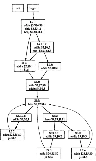
Throughout this chapter, the process of converting an object file into a program struc-ture tree will be demonstrated via the example program in Figure 3-1. This program snippet performs no useful computation, but it does contain several interesting control flow struc-tures. First, it contains a compound conditional, the 'or' statement with three terms. Then, the strand enters an infinite loop. The body of the loop contains an if/else if/else block. Together, these control flow structures constitute the majority of control flow blocks that exist within C programs. As this chapter describes the conversion from binary to program structure tree, each step will be demonstrated on this example program strand.
3.1
Extracting Basic Blocks from an Object File
The C-Flow compiler uses the Raw rewriter infrastructure, created by Jason Miller and Paul Johnson, to convert input binaries into an analyzable form. Using disassembly tools based on the GNU libbfd infrastructure, the rewriter transforms raw object code into a set of basic blocks. Basic blocks consist of a sequence of instructions that may only be entered at this first instruction and exited at the last. Branch or jump instructions may only occur as the last instruction in a basic block. Because basic blocks always finish by either falling to the next block, jumping to some other block, or branching, a basic block's exit point may lead to a maximum of two successor blocks.
After extracting basic blocks from the object file, the C-Flow compiler uses the rewriter to scan the binaries' ".note" and ".data" sections and locate C-Flow communication com-mands. As described in Section 2.2, channel declarations are stored in the strand's data segment and the routing information associated with messaging commands is stored in the note segment. Using this information, the compiler marks all basic blocks which perform network communication. It also links each communication instruction within a basic block
#include "raw.h" #include "cflow.h" tilel = cLtile...endpoint(0,1); void begino
{
int random = 0; int num; 10random = cLreceive(tilel, "random");
if(random > 10 jj random < 0
II
random == 5){ num = 1; } else { num = 0; } 20 for(;;){ if(num == O){cf-send(1, tilel, "first");
}
else if(num % 2 == 1){
cLsend(2, tilel, "odd"); }
else {
cLsend(3, tilel, "even"); 30
}
to the channel used by that instruction.
Once communication instructions have been identified and their channel usage noted, the compiler groups basic blocks into functions. Functions are identified as starting with some global label, such as "begino" or "mainO" and continuing until a return instruction is executed. Once all of a strand's subroutines have been identified, the basic blocks belonging to each function are identified and assembled into a final, per-function control flow graph. These control flow graphs contain all of the basic blocks in a function, the edges where control flow moves from one block to the next, and two special nodes: entry and exit. The entry and exit nodes denote the function's entry point and exit point, respectively, and their creation simplifies some of the later static analysis phases.
The input control flow graph for our example program appears in Figure 3-2. Every node in the graph, except for "entry" and "exit", represents some basic block, and the instructions within that basic block are shown inside the control flow node. Interestingly, the "exit" node is not connected to the rest of the control flow graph. This happens because our example program finishes in an infinite loop and does not exit. At this point in compilation, infinite loops are allowable, though, so this control flow graph can be passed to later stages in the C-Flow compiler.
In summary, the first phase of the control flow extraction process converts input object files into control flow graphs. Each strand's CFG is then analyzed to determine which blocks belong to which subroutines; the CFG is then split so that there is one control flow graph for each function in the binary. Finally, information from the .data and .note segments of the binary is used to annotate the per-function CFGs, indicating which instructions are messaging commands and what channel each message uses. At the end of this process, each strand object file has been converted into a set of control flow graphs, one for each function and each with its internal messaging commands flagged.
3.2
Preparing the Control Flow Graph
The remaining stages in the program structure tree process are designed to isolate single-entry, single-exit regions within each function's control flow graph. These regions can be characterized as loops, if statements, etc. in order to construct a tree representing the control flow hierarchy of different strands. Many of the algorithms used to perform this
[ ]
begin:
L7 1: addu $3,$24,$0 stiu $2,$3,11 beq- $2,$O,$L4 L7 1.1.t: addiu $2,$0,5 bne- $2,$3,$L3 adadu $230,1 addu $2 ,$, $Lf: addu $3,$2,$0 addiu $4,$0,1 $L6: bne- $0,$2,$L9 $L6.2.t: $L9:addiu $5,$O,l bne- $4,$3,$Ll I
L7 $2,5$ $L9.3.t: $LI 1:
jdd $ 5,$ addiu $5,$0,2 addiu $5,$0,3
V7 3: L7 4:
addu $24,$5,$0 addu $24,$5,$0
j+ $L6 j+ $L6
region identification require that the control flow graph have particular characteristics. For instance, our control graph already has the property that all basic blocks have no more than two exit edges.
The region recognition algorithms to be described in later sections required two other graph properties, as well. First, each function must have a single entry and a single exit node, and all nodes must be able to reach the exit node. This property forbids infinite loops, so infinite loops must be transformed into regular loops, as described in the next section. The infinite loop elimination algorithm and several later compiler stages also require that the graph be "complex-node free": any control flow graph nodes with multiple entry edges may have only one exit edge, and any node with multiple exit edges may have only one entry edge.
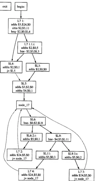
In order to establish this property, the C-Flow compiler splits any control flow nodes which have more than one entry edge and more than one exit edge. Each "complex node" is transformed into two "simple nodes". The first node has the original entry edges, the second node has the original exit edges, and a single edge goes from the first to the second. Thus, the overall control flow pattern is unchanged, but the graph now satisfies the "complex-node free" property. The results of this transformation on our example program appear in Figure 3-3; note that node $L6 from Figure 3-2 has been split into two nodes - "node_17" has all of the original node's entry edges, and the new $L6 has the original exit edges.
3.3
Eliminating Infinite Loops
Many compiler algorithms, including some in C-Flow, rely on "dominator analysis" [11]. A node 'a' dominates some node 'b' if all paths from the entry point to 'b' include 'a'. Thus, 'b' can only be reached by going through 'a'. Similarly, the node 'b' post-dominates 'a' if all paths from 'a' to the exit point contain 'b'. The 'dominator' and 'post-dominator' properties can be similarly defined for edges. The post-domination property is particularly useful for control flow analysis. For instance, if basic block 'a' has two outgoing edges due to a branch operation and basic block 'b' post-dominates 'a', 'b' will execute regardless of the branch condition in 'a'.
Unfortunately, many of the useful properties of post-dominator analysis are only useful in control flow graphs that do not contain infinite loops. The very definition of post-domination
L
xit begin: L7 1: addu $3,$24,$0 sltiu $2,$3,11 beq- $2,$O,$L4 L7 1.L.t: addiu $2,$0,5 bne- $2,$3,$L3 ddu , , add u $ 0 ,$ $L4:addiu $ 2,$O,1 adu$L3: $
j+ $L5 Idd / 2$O $L5: addu $3,$2,$0 addiu $4,$O,1 node_17 $L6: bne- $0,$2,$L9 $L6.2.t: $L9: addiu $5,$0,1 bne- $4,$3,$L11 L7 2: jaddu 4, $ addiu $5,$0,3 dd$5,$0,2 L7 4: L73:
addu $24,$5,$0 addu $24,$5,$O
j+ node_17 j+ node _I
given above implies that all paths can reach the exit point, a prerequisite which fails if the
CFG contains infinite loops. This section describes a method for removing infinite loops
from a CFG by inserting "fake loop exits"; a branch within an infinite loop that appears to allow a path to the exit node even though the branch will never actually be taken. The process of removing infinite loops has two phases. After identifying infinite loops, we find a "fake exit point" or "breakout node" for each infinite loop. Then, a "reentry point" is found for each breakout, such that the reentry creates a path from the infinite loop to the exit node.
3.3.1 Identifying Infinite Loops and Finding Breakout Edges
Determining whether a control flow graph contains any infinite loops is straightforward. Each node is given a property node.exit, initialized to 0. Starting at the exit node, each node's predecessors are recursively marked with node. exit = 1, until all the nodes which can
reach the exit node have been marked. If any nodes have node.exit = 0, an infinite loops is
present. Discovering which nodes belong to which infinite loops is slightly more involved, but can still be done in O(N) time.
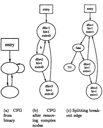
In order to identify which nodes are in which infinite loops, we add two properties to each node in the control graph: node.dfs and node.hi. Node.dfs is a node's index in a depth first traversal of the control flow graph, starting at the entry point. Node.hi, defined in [10], is the highest node in the depth first traversal tree that can be reached from a particular node (i.e. the minimum value of node.dfs that can be reached from a node). The value of
node.hi can be determined in O(N) time using a reverse depth first order traversal of the
graph in which A.hi is set to the minimum value of node.hi found amonst node A's children. That is, A.hi is set to the minimum value of node.hi that can be reached by following a single edge from A. An example control graph, including values of the above properties, appears in Figure 3-4(b).
An infinite loop exists if there is some non-exitable node (node.exit = 0) for which node.hi is less than node.dfs. Each unique infinite loop has a different value of "hi", and
there is a unique node with dfs = hi. These nodes are referred to as "breakout nodes". Because each breakout node must have at least two entry edges, one entering the infinite loop and the other from the loop body, and the control flow graph has no complex nodes, we know that each breakout node will have a single exit edge. Any infinite loop that originally
entry (a) CFG from binary entry dfs=1 hi=1 exit=O b dfs=2 hi=1 exit=O dfs=3 hi=1 exit=O (b) CFG after remov-ing complex nodes entry dfs=1 hi=1 exit=1 fake dfs=2 ?? hi= exit=1 dfs=3 W1=1 exit=1 (c) Splitting break-out edge
Figure 3-4: Finding and splitting a breakout edges to remove infinite loops
did not have a single exit edge, as in Figure 3-4(a), will have one inserted when the complex nodes are eliminated as in Section 3.2. By splitting each "breakout edge" to insert a node with a "fake exit branch" leading to the rest of the program, the infinite loop is eliminated, as in Figure 3-4(c).
3.3.2 Finding Reentry Points for Breakouts
Once a "breakout" has been created for each infinite loop, the algorithm must determine where the breakout edge should reenter the control flow graph. An obvious choice is to have each breakout go directly to the exit node; this approach is simple and clearly guarantees that all nodes in the control flow graph will have a path to the exit node, as required for post-dominator analysis.
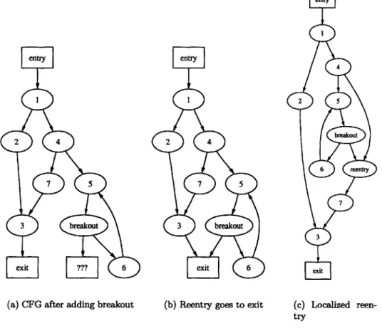
However, reentering directly at the exit node has some undesirable consequences. Con-sider the control flow graph in Figure 3-5(a). This program snippet consists of one if statement nested within another. One of the branches of the inner if statement leads to an infinite loop, which has already had its breakout point discovered. If the breakout is
assigned to reenter at the exit node, we have a case as in Figure 3-5(b). In this case, some program structure has been lost because one of the branches of the inner if statement reenters after the merge point for the outer statement. Thus, what was once two nested if statements has turned into a valid control flow graph that could not be created in C without the use of 'goto' statements.
Since C-Flow relies on hierarchical control flow to merge separate strands, the loss of control flow structure in Figure 3-5(b) is problematic. Fortunately, the nested if statement structure can be preserved by selecting the reentry point as seen in Figure 3-5(c). In this case, the breakout edge has been given a reentry point in the other branch of the inner 'if' statement, preserving the nested control flow structure.
Fortunately, there is a relatively simple algorithm which selects the infinite loop reentry point so as to reenter the control flow graph without disturbing the nested control flow hierarchy. For each infinite loop breakout, we simply scan the CFG for a node which both dominates the breakout node and can reach the exit node. If such a node exists, we simply scan the path from the dominating node to the exit, searching for an edge which post-dominates the dominating node. When such an edge is found, it is split into two edges, a node inserted in the middle, and an edge added from the infinite loop breakout to the node in the middle of the split edge. If there is no node which both dominates the infinite loop breakout node and can reach the exit, the breakout node is simply attached to the exit node, as before.
For example, in Figure 3-5(a), nodes 5, 4, and 1 dominate the infinite loop. Scanning from the breakout node upwards, we find that node 5 cannot reach the exit node. Moving on, node 4 does have a path to the exit node, so we search for some edge on a path from node 4 to the exit which post-dominates node 4. Since node 4 has only one path to the exit, the edge between 4 and 7 immediately post-dominates 4. This edge is split, creating the reentry node, and the breakout edge is attached to the new node, as seen in Figure 3-5(c).
The example program from Figure 3-1 does contain an infinite loop. The control flow graph for this program, immediately before breaking the infinite loop, appears in Figure 3-3. The breakout node for this infinite loop is placed between "node-17" and "$L6". Nodes "$L5", "$L7_1", and "begin" all dominate the breakout, but none can reach the exit. Con-sequently, the infinite loop's fake reentry point is assigned to the exit node, as seen in Figure 3-6.
entry
2 4
7 5
3 breakout
exit ??? 6
(a) CFG after adding breakout
entry
2 4
7 5
3 breakout
exit 6
(b) Reentry goes to exit
entry 4 2 5 breakout 6 reentry 7 3 exut (c) Localized reen-try
node_18 begin: L7 1: exit $L6: addu $3,$24,$0 x bne- $0,$2,$L9 sltiu $2,$3,11 beq- $2,$O,$L4 $L6.2.t: $L9: L7 I.$.t:
addiu $5,$O,l bne- $4,$3,$L1 1 bne- $2,$,$53
$L9.3.t: $L11: $L3:
addiu $5,$0,2 addiu $5,$0,3 addiu $2,$O,1 addu $2,$O,$O
L7 2: L7 3: L7 4: $L5:
addu $24,$5,$0 addu $24,$5,$0 addu $24,$5,$0 addu $3,$2,$0
j+ node_17 j+ node_17 j+ node_17 addiu $4,$0,1
node_17
3.4
Isolating Loop Bodies
The final transformation applied to each function's control flow graph before generating the program structure tree isolates a loop's body from its entry point. This separation is helpful when isolating control flow regions within the loop body; it allows the loop body to appear as a single-entry, single-exit region when the program structure tree is created.
Isolating the loop body from the entry requires identifying each loop entry node and determining which of the entry node's incoming edges come from the loop body and which come from the rest of the control flow graph (the entry edges). This information can be determined using dominator analysis, which is feasible now that all infinite loops have been removed. Using the dominance algorithm defined in [11], we first determine each control flow node's dominator set. Then, for each node 'a' in the graph, we check for any incoming edges coming from a node dominated by 'a'. If any such edges exist, the node is a loop entry point.
Once the loop entry points have been determined, the edges coming into each entry point 'a' are segregated into two sets, one composed of edges coming from nodes dominated
by 'a' and the other composed of edges from nodes not dominated by 'a'. If there is more
than one edge in either set, a new node is created to receive the edges in that set. A single edge is then created from the new node to 'a', thus creating a single edge by which all loop body nodes reach the entry point and a single edges by which all external nodes reach the entry point. The result of this operation on our example program appear in Figure 3-7. In this case, a new node "node_19" has been created. All of the edges from the loop body are connected to node_19, and a single edge goes from that node to the loop entry point,
"node_17".
After isolating loop bodies, the control flow graph is ready to be converted into a program structure tree. At this point, the CFG has no complex nodes or infinite loops, its loop bodies have a single entry and a single exit edge, and each basic block is marked with the channel information for any messaging operations the block may contain.
3.5
Constructing the Program Structure Tree
A program structure tree (PST), first described in (10], provides a hierarchical description
class = 2 class =7
ext bne- $0,$2,$L9 be I
class =5 class = 6 class = 2
L7 1:
$L6.2.t: $L9: addu $3,$24,$0
addiu $5,$Ol | bne- $4,$3,$L I Isltiu $2,$3,11
beq- $2,$0,$L4
class =5 class =4 class =3 class= 11
$L9.3.t: $L11: L7 1.1.t:
class 8 addiu $5,$0,2 addiu $5,$0,3 addiu $2,$0,5 class 12
addu $24,$5,$O class = 4 class = 3 class = class = 10
$LL4 $14:
class = 5 addu $24,$5,$0 addu $24,$5,$0 addu $2 0,$0 addiu $2,$,1
j~noe_19 j~noe_19j+ $L5
class =4 class =3 class = I class =9
single-entry, single-exit (SESE) regions within the control flow graph. These SESE regions may be nested within each other to form a tree. For example, an if statement has a single entry point (before the branch) and a single exit point (after the two forks merge), so an if statement will appears as a SESE region in the control flow graph. An if statement might be embedded within a loop body, which is inside a simple loop (another SESE region), which itself might be inside some other control flow structure. Thus, the program structure tree represents the nesting of SESE regions in the CFG. Within the PST itself, nodes represent
SESE regions and edges represent the nesting of one region within another. Thus, the
program structure tree is simply a heirarchical representation of the control flow graph; the
PST can be built from a CFG and vice versa.
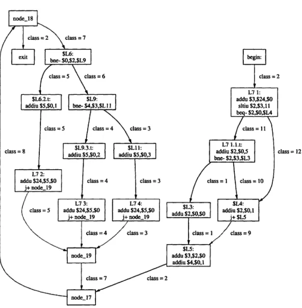
For example, Figure 3-8 shows the program structure tree corresponding to the control flow graph after loop body isolation (Figure 3-7). The top level function, begin(), has four sequential SESE regions. A careful comparison of this PST to the control flow graph it represents reveals that each SESE region corresponds to some element of the hierarchical control flow. For example, the SESE region that begins with "L7-1" and ends with "$L5" corresponds to an "or" statement in the original program.
The creation of the PST is performed using the algorithm described in [10]. This algorithm runs in O(N) time and is based on the concept of "cycle equivalence". Two edges in the control flow graph are cycle equivalent iff for all cycles C, C contains either both edges or neither edge [10]. It turns out that marking each edge with a "cycle equivalence class" makes the recognition of SESE regions trivial -any pair of edges in the same class forms a SESE region. The control flow graph in Figure 3-7 has the cycle equivalence class number marked on each edge. The relationship between cycle equivalence and the SESE regions in the program structure tree is apparent; for example, top level SESE regions in the program structure tree are bordered by edges in cycle equivalence class 2.
3.6
Region Type Recognition
-
the Message Structure Tree
Having created a program structure tree for each subroutine in each strand object file, the C-Flow compiler is almost ready to begin merging the separate strands into a single global messaging schedule. However, two characteristics of the PST make it less than ideal for use in merging. First, the leaf nodes in a PST are basic blocks, but message schedules are
begin()
entry: begin entry: L7 I entr: node_ 7 enr:xt
exit: begin exit: $L5 type: simpleoopx:
enr:$entry: $14 entry: $L6
exit: $3 xt:$7L4 exit: node_19
entry: $L6.2.t entry: L7 2 entry: $L9.3.t entry: L7 3 entry: $L1 1 entry: L7 4 exit: $L6.2.t exit: L7 2 exit: $L9.3.t exit: L7 3 exit: $L1 1 exit: L7 4
Figure 3-8: Program structure tree for our example program
a function of messaging commands within those basic blocks. Secondly, the single-entry, single-exit regions within the PST do not have any type information. That is, the PST recognizes SESE regions and describes their nesting, but it does not indicate whether a particular region is a simple basic block, an if statement, or a loop. Having this type information is critical in order to guarantee that send / receive pairs in different strands have the same control dependencies.
In order to address these weaknesses, we introduce the "message structure tree" (MST). Like the PST, the message structure tree has nodes representing SESE regions (with added type information), but it allows several other node types as well. These other nodes include sequences, function calls, and messaging operations. Function calls and messaging opera-tions are always leaf nodes in the MST; they are the primitives contained in the bodies of loops and other control flow structures. The body of the MST is made up of alternating layers of region nodes and sequence nodes. The rules governing which node types are al-lowed as children of a particular node type are summarized in Table 3.6; the purpose of each node type and the reasons for these rules will be explained in the next few sections. For reference, a MST corresponding to our example program appears in Figure 3-11.
3.6.1 Sequences
Sequence nodes in the MST provide an ordering for their child nodes. For example, the node "entry seq" in Figure 3-11 has three children, indicating the program will first receive


![[Rp] Parallelization of an object-oriented FEM dynamics code](data:image/gif;base64,R0lGODlhAQABAIAAAP///wAAACH5BAEAAAAALAAAAAABAAEAAAICRAEAOw==)