Characterization and Control of an Interactive
Robot
by
Stephen Paul Buerger
B.M.E., University of Dayton (1999)
Submitted to the Department of Mechanical Engineerin
MASSACHUSET TS INSTITUTE
in partial fulfillment of the requirements for the degree
OFTECHNOLOGYMaster of Science in Mechanical Engineering
JUL 16 2001
at the
LIBRARIES
MASSACHUSETTS INSTITUTE OF TECHNOLOGY
BARKER
February 2001
@
Massachusetts Institute of Technology 2001. All rights reserved.
Author...
Department of Mechanical Engineering
January 9, 2001
Certified by...
.
.V...
=...Neville Hogan
Professor
Thesis Supervisor
Accepted by..
... ... ... ....Chairman, Department Committee on
Ain A. Sonin
Graduate Students
Characterization and Control of an Interactive Robot
by
Stephen Paul Buerger
Submitted to the Department of Mechanical Engineering on January 9, 2001, in partial fulfillment of the
requirements for the degree of
Master of Science in Mechanical Engineering
Abstract
The field of rehabilitation robotics demands robots that can interact softly with the patients they treat while also bearing substantial loads. This thesis discusses the char-acterization of a screw-driven module that, when added to an existing therapy robot, will expand the workspace of this robot from two dimensions to three, broadening the effectiveness of the therapy that can be delivered. The results of the characterization are presented and provide a thorough understanding of the control electronics, the conversion of control from the signal domain to mechanical power, and the properties of the mechanical transmission. A detailed study of friction is included, as friction was found to be a dominant factor in design performance. The use of active con-trol methods to compensate for friction and to improve performance is considered and discussed. Suggestions are presented concerning the further examination of these types of controllers to facilitate the design of robots for rehabilitation and interactive machines in general.
Thesis Supervisor: Neville Hogan Title: Professor
Acknowledgments
The work described here, though enjoyable in its own right, has been made infinitely more so thanks to my contact with many great people. Foremost among these is my advisor, Neville Hogan. Neville's prominence in his field is no accident, and his insight is rivaled only by his enthusiasm. A few minutes with Neville has never failed to revitalize me and send me in the right direction.
Brandon Rohrer has been indefatigable in his willingness and ability to answer my many, many questions. In fact, he has refined this art to the point that all I must do is sit down to write him an email and the answer often descends upon me. Like Brandon, Max Berniker helped me immensely with this thesis and has greatly extended my understanding of our field through our many discussions, all this while captaining our immensely successful hockey team and sparking a hot new recording group.
Special thanks to Kris Jugenheimer and Dustin Williams, with whom I designed the hardware discussed here. Without their clever design work, the characterization could never have happened. Igo Krebs provided useful guidance thanks to his experi-ence in getting these robots successfully into the hospitals. Lori Humphrey can solve almost any problem with a smile. Jerry Palazzolo, James Celestino, Sue Fasoli, and Phil Tang round out a top notch research group.
Thanks also to all the members of the Hunter lab for the use of all their resources and especially for all the Newman Lab camaraderie. They have grown too numerous to list completely, but Bryan Crane and Patrick Anquetil have become close friends and confidants. Bryan and I have faced many of the same learning curves and adjustments, and having somebody in the same boat is always appreciated. Patrick can always pick me up when I am down. Keng "KH" Lim and Luke Sosnowski are sorely missed. Thanks also to John, Peter, James, Robert, and all the rest.
My parents have been very supportive and are always there to talk, even when I know they just want me to come home. Thanks to all my family and my tremendous set of friends from UD, MIT, and everywhere else, especially to Liz for all her support. I miss them all greatly and am constantly hoping they will continue to visit me here on the East Coast.
This work has been partially supported by a fellowship from the Department of Defense, and by the Winifred Masterson Burke Medical Research Institute.
Contents
1 Introduction
1.1 MIT-MANUS and MIT-MANUS II . . . . 1.2 A 3 Degree of Freedom Therapy Robot . . . . 2 Design Process
2.1 Major Requirements . . . . 2.1.1 Workspace Dimensions and Endpoint 2.1.2 Minimum Endpoint Impedance . . . 2.1.3 Other Important Requirements . . . 2.2 Configuration Selection . . . . 2.2.1 New 3 Degree of Freedom Designs . . 2.2.2 Advantages of MANUS . . . . 2.2.3 SCARA-based designs for 3 degrees o 2.2.4 Adaptability of MANUS . . . . 2.2.5 Transmission Selection . . . . 2.3 Screw-Driven Design . . . . Forces f freedom. 3 System Operation 3.1 Hardware Overview . . . . 3.1.1 Rollnut . . . . 3.1.2 Linear Bearing . . . . . 3.1.3 Mounting Support . . . 3.1.4 Flexible Coupling . . . . 17 19 21 25 25 25 27 30 31 31 31 32 32 33 34 37 . . . . 37 . . . . 37 . . . . 40 . . . . 42 . . . . 43
3.2 3.3 3.4 3.1.5 Alignment Difficulties ... 3.1.6 Servomotor . . . . 3.1.7 Servoamplifier . . . . 3.1.8 Position Sensor . . . . 3.1.9 Force Sensor . . . . 3.1.10 Adjustable Handle Module 3.1.11 Vertical Locking Device . Software Overview . . . . Typical System Operation . . . . Studying the system . . . . 4 Signal to Mechanical Power Subsystem
4.1 Amplifier and Actuator analysis . . . . 4.1.1 Low Frequency Static Testing . . . . 4.1.2 Amplifier Frequency Response . . . . 4.1.3 Torque frequency response . . . . 4.1.4 Limitations of delay information . . . . . 4.2 Subsystem conclusions . . . .
5 Transmission Subsystem
5.1 Parameters to be identified . . . . 5.1.1 The importance of friction . . . . 5.1.2 Why do we need to know? . . . . 5.2 Friction Identification . . . . 5.2.1 Understanding Machine Friction . . . . . 5.2.2 Model Simplifications . . . . 5.2.3 Experiment Design . . . . 5.2.4 Experimental Results . . . . 5.2.5 Model for Friction in the Screw Module . 5.3 Inertia Identification . . . . 5.3.1 Estim ation . . . . . . . . 4 3 . . . . 4 7 . . . . 4 8 . . . . 4 8 . . . . 4 8 . . . . 4 9 . . . . 4 9 . . . . 4 9 . . . . 5 0 . . . . 5 3 55 55 . . . . 55 . . . . 57 . . . . 62 67 . . . . 69 71 . . . . 7 1 . . . . 74 . . . . 75 . . . . 76 . . . . 76 . . . . 85 . . . . 87 . . . . 9 0 . . . . 109 . . . . 116 . . . . 118
5.3.2 Experiment . . . .
5.3.3 Experimental Results . . . .
5.4 Subsystem Conclusions . . . .
6 Controls Analysis
6.1 Linear Impedance Controller . . . . 6.2 Friction Compensation Techniques . . . . 6.2.1 Feedforward Controllers . . . . 6.2.2 Feedback Controllers . . . . 6.3 Applying Friction Compensation to an Impedance Controller
6.3.1 Impedance and Interaction . . . . 6.3.2 Feedback Control . . . . 6.4 Compensation Applied to the Module . . . . 6.4.1 Negative Software Damping . . . . 6.4.2 Feedforward Friction Compensator . . . . 6.4.3 Performance Enhancement with Force Feedback . . . 6.4.4 Controller for the Screw Module . . . . 7 Conclusions
7.1 A Framework for Further Investigation . . . . Appendix A Compliant Mounting Analysis
A.1 Model for Compliant Mounting . . . . A.1.1 Driving Frequencies . . . . A.2 Case 1: Motor and mount piece move with screw . . . . A.3 Case 2: Motor and mount piece grounded . . . . A .3.1 D am ping . . . . A.4 Case 3: Tuned Vibration Absorber . . . . A .5 C onclusions . . . . Appendix B Software Timing Study
B .1 T esting . . . . 119 121 124 125 . . . . 125 . . . . 131 . . . . 131 . . . . 133 . . . . 134 . . . . 134 . . . . 135 . . . . 136 . . . . 136 . . . . 138 . . . . 140 . . . . 147 149 150 153 153 154 155 156 157 157 161 163 163
B.2 Intentional Delays . . . . 164
Appendix C Models for Frequency Response 167
C.1 Sim ulated system . . . . 167 C.2 Amplifier Characterization Model . . . . 167 C.3 Actuator Characterization Model . . . . 169
Appendix D Conference Paper Detailing the Design 171
List of Figures
1-1 MIT-MANUS II therapy robot. ...
1-2 Patient working with MIT-MANUS . . . .
2-1 Solid model of the new module for vertical motion. 3-1 3-2 3-3 3-4 3-5 3-6 3-7 3-8 3-9 3-10 3-11 4-1 4-2 4-3 4-4 4-5 4-6 4-7 . . . 20 . . . 20
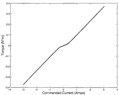
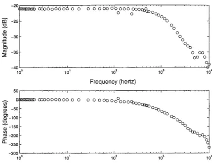
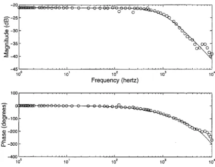
Screw/nut interface of a Rollnut. . . . . Rollnut assembly. . . . . Reaction force and torque at nut . . . . Linear ball bearing, rail and carriage. . . . . Structural support/mount piece. . . . . Helical beam coupling joining motor shaft to screw. . . . . Sources of screw binding . . . . Grommet used to provide compliance in top bearing mounting... System schematic .. . . . . Virtual spring and damper . . . . System block diagram . . . . Locked rotor testing . . . . Torque vs. commanded current . . . . Commanded current vs. desired torque, for linearization . . Torque vs. current, linearized . . . . Amplifier frequency response, DSA . . . . Frequency Response data as in Figure 4-5 with fitted model. Amplifier frequency response, sampled at 2 kHz . . . . 34 39 40 41 42 43 44 45 46 51 52 54 . . . . . 56 . . . . . 57 . . . . . 58 . . . . . 58 . . . . . 60 . . . . . 61 . . . . . 62
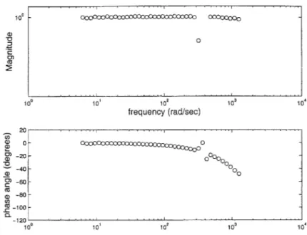
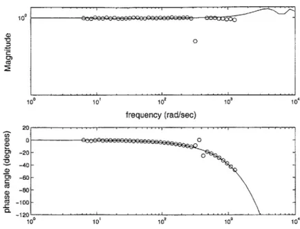
4-8 Amplifier frequency response, data and model . . . . 4-9 Actuator frequency response . . . . 4-10 Actuator frequency response, data and model . . . . 4-11 Phase vs. frequency, linear scale . . . . 4-12 Actuator frequency response, sampled at 1 kHz . . . . . 4-13 Ideal sampling of a unity gain plant. . . . . 4-14 Sampling a system with a partial sample delay. . . . . . 5-1 Translational free body diagram . . . . 5-2 Asperities in contact . . . . 5-3 Anticipated friction velocity dependence . . . . 5-4 Experimental setup, constant velocity testing . . . . 5-5 Interface for force transmission for friction testing against 5-6 Double ball-joint interface . . . . 5-7 Friction measurements in the frequency domain . . . . . 5-8 Friction measurements in the frequency domain, closeup 5-9 Optimal low pass filter . . . . 5-10 5-11 5-12 5-13 5-14 5-15 5-16 5-17 5-18 5-19 5-20 5-21 5-22
Velocity dependence of friction at bottom of screw Velocity dependence of friction at top of screw . . Position dependence of friction . . . . Position dependence of friction, range of speeds Friction force vs. position and velocity . . . .
Repeatability of friction measurements . . . .
Velocity dependence of friction, downward . . . .
Velocity dependence of friction, downward . . . .
Position dependence of friction, downward . . . .
Friction in both directions . . . . Force with and against gravity, positive direction Force with and against gravity, negative direction
Friction force with gravity . . . .
63 . . . . 64 . . . . 65 . . . . 66 . . . . 67 . . . . 68 . . . . 69 . . . . 73 . . . . 78 . . . . 79 . . . . 88 gravity. . . 89 . . . . 89 . . . . 92 . . . . 92 . . . . 94 . . . . 95 . . . . 96 . . . . 98 . . . . 99 . . . . 100 . . . . 101 . . . . 102 . . . . 103 . . . . 104 . . . . 104 . . . . 106 . . . . 106 . . . . 107
5-23 5-24 5-25 5-26 5-27 5-28 5-29 5-30 5-31 5-32 5-33 5-34 6-1 6-2 6-3 6-4 6-5 6-6 6-7 6-8 6-9 6-10 6-11 6-12 6-13 A-1 A-2 A-3 A-4
Force vs. position, PD controller, 100 N/m . . . . Force vs. position, PD controller, 1000 N/m . . . . System under PD control interacting with human arm . . . . Model appearance for desired system behavior . . . . Negative viscous damping . . . . System under PD control with friction and gravity compensators. Block diagram, PD controller and friction estimator . . . . Performance with friction compensator . . . . Stiction that remains with friction compensator . . . . Performance with force feedback controller . . . . Simulation for force feedback . . . . Simulated results using PD controller . . . . Simulated results using force feedback . . . . Model for system with compliance . . . .
Moment of inertia about pivot vs. nut location, Case 1. Natural frequency vs. nut location, Case 1. . . . . Natural frequency vs. nut location, Case 2. . . . . Friction force vs. position for gravity identification . . . Gross fit of position dependence, upward . . . . Fit for position dependence of friction, upward . . . . Fit for velocity dependence of friction . . . . Friction minus friction model, upward . . . . Fit for position dependence of friction, downward . . . . Fit for velocity dependence of friction, downward . . . . Friction minus model . . . . Low pass filter . . . . Acceleration and mass times acceleration curves . . . . . Acceleration and mass times acceleration curves, closeup Calculated inertia vs. time . . . .
. . . . 109 . . . . 112 . . . . 112 . . . . 114 . . . . 114 . . . . 115 . . . . 117 . . . . 117 . . . . 120 . . . . 122 . . . . 122 . . . . 124 127 128 130 130 137 138 139 140 141 143 144 145 145 . . . . 154 . . . . 155 . . . . 156 . . . . 157
A-5 Model for system with tuned vibration absorber. . . . . 158
A-6 Bond graph of tuned vibration absorber . . . . 159
A-7 Frequency response with tuned vibration absorber . . . . 160
List of Tables
3.1 Approximate timing of major software operations . . . . 50 5.1 Estimated contributions to endpoint mass, by component. . . . . 118 B.1 Approximate timing of software operations in each sampling period. . 166
Chapter 1
Introduction
Recovery from brain injury is a major concern of medical researchers. Stroke is a leading cause of disability in the United States [23] and a major health problem worldwide. With an aging population, particularly in North America, this problem is not likely to subside.
Many patients suffer as a consequence of brain injury partial or complete loss of motor control in their limbs. Such paralysis is manifested in several different ways but often appears as hemiplegia, a paralysis concentrated on one side of the body. Some patients eventually recover partial or complete use of the affected limbs; the recovery process is typically on the order of weeks and months, and can vary significantly from patient to patient.
Recent research has shown that recovery can be enhanced through the adminis-tration of physical therapy. Furthermore it has been shown that the use of robotic therapy aids can speed the recovery process. Aisen et al. [2] studied recovering stroke patients and showed that the performance of an experimental group, that received robot therapy in addition to the typical therapy regimen, improved by a greater amount than the performance of a control group in a statistically significant sense.
The importance of the results from Aisen et al. must not be overlooked. These findings are significant as they demonstrate the importance of therapy and the viabil-ity of robotic therapy. Even beyond these important realizations, the work potentially points toward more revolutionary ideas in motor recovery. Clearly therapy helps to
speed and complete recovery. However most therapy techniques in use in today's hos-pitals and clinics are not founded in the science of human motion and motor recovery, but are largely derived from intuition about the types of movements that are useful, or are specifically targeted to the completion of useful tasks for the patient. One might hypothesize that different types of therapy might affect recovery in different ways; thus one might discover techniques which are preferred for promoting recovery. As current understanding of the human motor control system is quite limited, the process of motor recovery could both assist in and benefit from the development of a better understanding of the biological processes at work. Such a full understand-ing could potentially lead to the creation of specific therapy routines providunderstand-ing for optimal recovery and targeting very specific types of lesions and patients.
The process proposed in the preceding paragraph is yet in its infancy, and is presented largely to provide the reader with a more fully developed "big picture" understanding of the importance and significance of the research described herein. The apparent potential of these ideas is great; as more information about human motor recovery is gathered, these ideas can be evaluated in the context of a greater understanding.
The uses of robot therapy are certainly not restricted to the long term vision of targeting therapy for optimal recovery. The technology has very immediate uses in complementing the work of physical and occupational therapists. Robotic therapy units are conceived of not to replace therapists but to expand their capabilities. With a robotic therapist, a patient may one day be able to receive therapy between sessions with his human therapist; this could be useful as patients tend to tire quickly but could potentially receive therapy several times a day. Perhaps a robot unit could be dispatched to the home of a patient recovering from brain injury so he could receive portions of his therapy without staying in or traveling to a hospital.
Robot therapy can also be extremely useful as a measurement tool. Clinical mea-sures of patient performance are largely based on subjective meamea-sures performed by the human therapist. The therapist tests the patient's strength and coordination in attempting one of several tasks. These measures, while widely accepted in the field,
are largely unscientific and are heavily susceptible to human error and bias. Con-versely, the robot can be used to quantitatively measure both the motion and the forces that the patient is producing to a high degree of accuracy. This data can be stored and analyzed to provide detailed information about patient recovery. Devel-oping consistent and successful ways of processing this data to provide information about the patient is an important part of robot therapy research.
The following section will describe the robot used in the clinical trials for robotic therapy.
1.1
MIT-MANUS and MIT-MANUS II
MIT-MANUS and MIT-MANUS II are the alpha and beta prototypes, respectively, of a first generation of robots designed to administer therapy to patients recovering from brain injury. The two robots differ only in subtle points of design.
The MANUS design [7, 1] utilizes a 5-bar Selective Compliance Assembly Robot Arm (SCARA) configuration to deliver power from its two stationary brushless DC servomotors to the point of patient interaction, a handle located in a planar workspace. MANUS II is shown in Figure 1-1.
When a patient works with the robot, his hand and forearm are strapped into a cradle attached to the robot's handle. The patient is seated at a table facing the robot and a computer monitor. The monitor provides the patient with visual feedback of his performance and goals. The patient plays video games, generally attempting to move his hand from point to point in a planar workspace parallel to the tabletop, as dictated by the game. The MANUS robots help in rehabilitation of the shoulder and elbow muscles but only for a certain set of movements in a horizontal plane. Figure 1-2 shows a patient playing a game on the robot.
In the period immediately following a stroke, a patient is often unable to move his impaired limb at all. In this early stage of recovery, the robot moves the patient's hand from point to point as the patient tries to complete the same moves. As the patient's condition improves, so does his performance, and the interaction with the
Figure 1-1: MIT-MANUS II therapy robot.
Figure 1-2: A patient receiving therapy MIT-MANUS.
robot becomes more evenly divided; he is moving the robot as much as the robot is moving him. Late in recovery, the robot is often used without power as the pa-tient pushes it around from target to target. The robot can also be used to provide resistance once the patient can move on his own, to help with strength training.
To deliver therapy in the way described in the preceding paragraph, a robot with a soft, compliant feel is required. In the MANUS design, this is achieved through the use of backdrive-able hardware and impedance control. The SCARA configura-tion, used with direct drive motors, is inherently backdrive-able. The importance of such a low-impedance interaction is addressed extensively throughout this thesis. Impedance control [19] provides a soft, stable environment for interaction. Using one implementation of impedance control the environment feels an apparent spring and damper between the endpoint position and the desired endpoint position at any given time.
The MANUS design has provided a platform for the successful robotic therapy research described above.
1.2
A 3 Degree of Freedom Therapy Robot
As mentioned above and in the work by Aisen et al., the administration of robotic therapy produces significantly greater recovery in patients than that seen in those who do not receive robot therapy. It is important to note, however, that the improve-ments are limited to the specific muscle groups exercised by the therapy; there is no significant generalization of improvement to other muscle groups [2]. Thus in order to provide therapy that will lead to full recovery, it is necessary to develop additional robot modules to target other specific muscle groups.
The first and second incarnations of MIT-MANUS, as described in the preceding section, provide for motion exercising the shoulder and elbow muscle groups through movements in a planar workspace oriented parallel to a tabletop. This workspace provides an excellent framework to train and study a controlled set of movements to evaluate the effectiveness of therapy and robotic therapy. The movements trained,
however, certainly do not encompass a full set of the useful motions for a normally functioning human being. Even for the elbow and shoulder groups, more extensive training is useful to learn tasks such as feeding and reaching, tasks that are essential for independence. It is critical that the patient eventually recover the ability to move against gravity, and to carry the weight of his arm in addition to other objects.
With this need in mind, a new module was designed to augment the MANUS configuration by providing for motion in a third degree of freedom. The planar workspace was expanded vertically into a three-dimensional workspace. No significant loss of planar function was suffered, and the capability to move up and down without the planar confines of MANUS was provided. The module offers greatly expanded therapy possibilities and will speed shoulder and elbow recovery.
A device was created that is mechanically simple and that meets the desired goals. The module was tested and analyzed extensively. The major limitations to module performance were identified and steps were taken to compensate for these limitations. This thesis discusses the development and implementation of a prototype of the new module design. The details of the design process are discussed elsewhere [22](see Appendix D); this document primarily focuses on the characterization, calibration, and identification of the robotic system, and of measures taken to bring the new module's performance into the desired specification range.
" Chapter 2 provides a brief discussion of the design and of a few of the major design decisions and the factors that motivated them. Also included is discus-sion of modifications made to the design because of revelations in the course of fabrication.
" Chapter 3 gives an overview of the major hardware and software components, and provides a detailed discussion of how the system works.
" Chapter 4 discusses the characterization and identification of the portion of the system providing transmission from the theoretical controller command to mechanical power at the motor shaft.
" Chapter 5 describes the process and results of examining the mechanical trans-mission in the device, from the motor to the port of contact with the patient. This includes an overview of the literature concerning machine friction, includ-ing theory and analysis, as this topic is central to study of the module.
" Chapter 6 discusses several approaches to impedance control of the module, including compensation techniques for the improvement of system performance through active control rather than mechanical redesign.
" Chapter 7 provides conclusions drawn from the work including suggested im-provements for this specific design and recommendations on how to build on this work.
Chapter 2
Design Process
This chapter discusses in summary the design of a therapy robot for training move-ment in a three-dimensional workspace. The design process for this device is described in greater detail in Appendix D [22]; this chapter simply attempts to provide the back-ground necessary to understand the design and the motivation for the work described here. Fundamental requirements for the device were defined. Based on these require-ments a large number of concepts for the new design were generated. These designs were considered and evaluated on the basis of their fulfillment of the requirements. The process of selecting a suitable configuration was an iterative one involving brain-storming, basic calculations, and systematic idea processing. This chapter is intended not to deductively justify the choice of design but to describe the general evolution of the design from a set of requirements and many unrelated ideas to the one idea actually developed.
2.1
Major Requirements
2.1.1
Workspace Dimensions and Endpoint Forces
The robot discussed here is, from conception, a three-dimensional analogue to the two-dimensional MANUS design. As such, the new robot is expected to approach or exceed the performance of MANUS in the planar workspace, and to provide analogous
performance in the spatial area above the workspace.
MANUS nominally offers a planar workspace that measures 15 by 18 inches (0.381 by 0.4572 in). The new device was targeted to offer a comparable range of motion vertically, nominally 18 inches (0.4572 m).
In order to offer sufficient stiffness, MANUS was designed to provide sufficient forces to counteract the forces that a typical patient can produce in each direction. Charnnarong provides a discussion of the determination of the targeted endpoint force for the MANUS-I robot [7]. He points out that most patients are weaker than an average weak person as documented in [11]. Charnnarong decides on an approach of designing for slightly greater power than necessary, and limits endpoint forces to approximately 10 lbf (44.5 N). This value is sufficient for most therapy, but does not provide enough power to overcome extreme patient conditions such as spasticity and tone. 10 lbf (44.5 N) is enough to offer performance comparable to MANUS and is therefore an acceptable minimum, but greater force capabilities may prove advantageous.
The new robot is required to meet similar force requirements in the plane. Fur-thermore the robot must offer significant force in the vertical direction. This force must be enough to compensate for the weight of a patient's arm as well as to offer sufficient forces for effective therapy. Vertical force producing capabilities are compa-rable to forces in the plane [11]. Following Charnnarong's reasoning, the robot should be able to provide at least 10 lbf (44.5 N) in addition to supporting the patient's arm weight.
Effective arm weight is a fairly complicated function not only of arm dimensions and mass, but also of arm configuration. Because of the large number of variables, some of which are difficult to estimate, a few simple experimental measurements were used to empirically determine a reasonable estimate of arm weight. Measurements were made both on healthy people attempting to minimize muscle action and on a recovering patient with a flaccid arm, in a variety of arm configurations. The patient was obese, so the measurements give an idea of the "worst case".
suspended from a fixed tripod via a spring scale. A force was then read from the spring scale. All measurements indicated a mass less than 2 kg, leading to a force less than 20 N.
Based on arm mass and desired force estimates, the target maximum endpoint force was set at approximately 65 N upward and 45 N downward.
2.1.2
Minimum Endpoint Impedance
The need for low impedance
The importance of providing the possibility of low endpoint impedance for this type of robot is worth emphasizing before specifically addressing the characteristics of any particular hardware. This point has great significance in distinguishing the technology discussed here from typical modern robots. Standard industrial robots are restricted to extremely high endpoint impedances. Often there is so much friction in the heavily geared transmission of such a robot that the manipulator cannot be moved without its actuators commanding its position. For a normal person this is an extremely "hard" feel, with virtually no compliance. Such robots are generally position or trajectory controlled. If an object obstructs their commanded path, they push it out of the way; if the object is "stronger" than the robot, then the robot breaks (or more likely triggers some sort of self-shutdown).
This feel is far from that desired for a therapy robot. A therapy robot should provide a soft environment with which the patient can interact. The robot should gently encourage the patient to move in the desired path, but should not generally interfere with the patient's own efforts to move. There is significant evidence to suggest that human upper-limb movement is organized based on hand motion in body-centered coordinates, rather than in jointspace [14]. If a key portion of the process of human motor control is achieving and potentially observing movement in an external coordinate frame, it is important not to infringe on the ability to move when encouraging motor recovery. It would be counter-productive to interfere with a patient's efforts to move, and doing this would likely result in ineffective therapy.
Ideally a therapy robot should offer the possibility of an endpoint impedance ranging from nominally zero to stiff enough that even a strong patient has difficulty moving it. This scenario offers the flexibility of administering therapy and performing evaluation in a variety of virtual environments, at the discretion of the therapist and attending physician. This goal permeates the entire development process of a therapy robot and is kept in mind at all stages of the design, characterization, and testing.
Defining Impedance
With the possibility of small endpoint impedance identified as a critical design goal, it becomes important to specifically define what this means. Minimizing endpoint impedance means, in the context of the design of this robot, minimizing both endpoint friction and effective endpoint mass.
For a port of interaction in a mechanical system, impedance can be understood as a relationship between the force and motion, specifically velocity, at the port. A port that acts as an impedance provides some force in response to a motion imposed on it. Such a port must interact with an admittance, a port that allows motion in response to some force. In our case, the environment or patient is viewed as an admittance, and the robot provides a certain endpoint impedance [19].
Impedance is dictated by the effective mechanical properties of a system at the port of interaction. For the linear case, this can be shown by considering, for example, a simple second order system described by the following equation:
M. + bii + kx = u (2.1)
where u is input force. In the Laplace domain, with the Laplace variable s, this system's transfer function form can be represented as:
U
U - Ms2 + bs + k (2.2)
Or, substituting V = sX where V is velocity,
U k
- =Ms + b + - (2.3)
V s
As impedance is defined as the left half of equation 2.3, the force necessary to produce a desired motion, it can clearly be seen that for the linear case any increase in M or
b will result in a higher impedance. It is also important to minimize k, the stiffness
about an operating point, but this is generally controlled in software for the class of designs that has no strongly preferred orientation. This is the case for the class of designs discussed here.
Although equation 2.3 represents a linear system with b a constant damping coeffi-cient and M a constant mass, note that this idea can be extended to nonlinear friction and state-dependent mass as well. This case effectively means that b and/or M is a function of time or the state. Clearly it can be seen that for minimum impedance, it is desirable to minimize b and M regardless of time or state.
Minimum Friction
In conjunction with the minimization of endpoint mass, discussed in the next section, friction minimization is essential to the new robot. If one seeks only to minimize friction, it is sometimes possible to replace a large amount of the potential friction with larger inertia, for example by eliminating geartrains in favor of large direct drive actuators. In a design where both friction and inertia must be minimized, however, this tradeoff must be tempered and carefully considered.
An overview of machine friction is reserved for Chapter 5, where it is presented in the context of the chosen design. Here it must only be noted that the minimization of friction was of primary concern from the beginning of the design process.
Minimum Mass
As the patient is intended to manipulate the endpoint of the robot by pushing and pulling it, minimizing the effective endpoint mass is important in keeping impedance
small. This can clearly be seen from equation 2.3 or from Newton's second law of motion, which can be stated as:
Z F = M. (2.4)
Clearly it takes less force to accelerate a smaller mass. As stroke patients are not expected to produce substantial forces in the early stages of recovery, it is important to keep the mass against which they must work to a minimum.
2.1.3
Other Important Requirements
A number of requirements beyond the endpoint force requirements and the minimiza-tion of endpoint impedance were carefully considered in the design of the new robot. Several of the most important are highlighted here.
Safety is always of primary concern, especially in a clinical environment such as that in which this robot must operate. This robot must be equipped with multiple safety systems to ensure safe operation and stable shutdown should the need arise. The design must be free of pinch points and must guarantee stability, even in the case of operator error.
The interface to the patient should have a "smooth" feel. The patient should feel comfortable in dealing with the robot, and should not get the impression of dealing with a mechanical device. To this end, it is important to keep any backlash and play in the system to a minimum, and to ensure that the system can actuate smoothly at extremely slow speeds.
It is preferable to create a system that utilizes electromechanical actuators for portability and easy use in a clinical environment. This requirement could be circum-vented but only with great difficulty.
MANUS-II is a compact, modular design that allows for easy transportation. It also keeps much of its bulky hardware away from the patient, so as not to appear too intimidating. It is preferable to preserve these qualities in the new robot.
2.2
Configuration Selection
2.2.1
New 3 Degree of Freedom Designs
Several configurations were proposed that involved a substantial departure from the style of MANUS and MANUS-II. These concepts used many different types of actu-ators and transmissions to produce motion in three dimensional space.
Each of the new configurations considered seemed extremely complex, and offered few advantages over many of the other designs. Complexity and cost, without any obvious advantages, were the main factors in eliminating such designs.
2.2.2
Advantages of MANUS
While the SCARA design used in MANUS is limited to two dimensional motion, it offers many properties advantageous to the application. The 5-bar closed chain mech-anism permits motion over a fairly large area with stationary actuators. Furthermore, within certain bounds of this area, the effect of the inherent nonlinearities in iner-tia and damping are not significant; this property permits the use of the specified workspace, much smaller than the total range of manipulator motion, with negligible deviations in inertia and damping. Foster's [15] results particularly illustrate this point, showing less than a 70 percent variation in endpoint inertia with direction. Coulomb friction and viscous damping variation is a bit more substantial, but these values are so low that it causes few real problems.
The long arms of the linkage require precise sensor resolution, but also reduce the effective endpoint mass substantially by providing mechanical advantage in backdriv-ing the actuators. The result is a large lever arm to aid in overcombackdriv-ing bearbackdriv-ing and actuator friction as well as actuator inertia.
A final advantage of the SCARA design is suggested by its name: Selective Com-pliance Assembly Robot Arm. While the device is extremely compliant (has very low impedance) in the plane of its actuation, it is extremely rigid in the third dimension. Thus the device has no problems bearing any vertical forces the patient places on it.
2.2.3
SCARA-based designs for 3 degrees of freedom
The several advantages of the SCARA configuration described above proved difficult to ignore. Many of these advantages are desired in the new device as well. There is no clear 3 dimensional analogue to a SCARA configuration; in other words there is no closed chain mechanism known to the author that provides the desired three degrees of freedom and the same advantages of a SCARA. Thus a class of design concepts developed that included the idea of employing a SCARA for two degrees of freedom and an additional actuation technique for the third degree of freedom.
One subset of such designs included the idea of moving the base of the SCARA to provide the third degree of freedom. Ideas included moving the entire linkage and its actuators vertically, or rotating the entire structure. Each of these ideas involved the need to move extremely massive actuators, greatly increasing endpoint inertia and requiring an extremely powerful third actuator. An alternative idea considered moving only the SCARA links vertically on shafts extending from the actuators, while keeping the actuators stationary. This idea was eliminated largely because of concerns about binding due to the large torques that would be transmitted to the sliding parts, and because the inertia was still substantial.
Another subset of SCARA-based designs included designs in which a new module is mounted at the handle of a robot resembling the existing robot, and is carried about the plane. This module provides the vertical motion. These designs were attractive because of the idea of modularizing the robot, of potentially meeting the desired criteria by simply adding a piece of hardware to the planar design.
2.2.4
Adaptability of MANUS
To consider the idea of adding a module at the endpoint of MANUS, it was necessary to evaluate the capability of the existing robot to support such a new device, and to bear the expected loads associated with vertical actuation.
Charnnarong's [7] work provides the calculations used in the structural design of the MANUS SCARA. Using an expected maximum vertical endpoint force of 20 lb
(89 N), he applies a design factor of 2.5. Then in designing the links to handle the maximum bending moment, he chooses a material that provides an additional design factor of 2.825, giving a total design factor of just over 7. The joints and bearings are designed with similar loads and design factors in mind.
Preliminary calculations suggested that an endpoint-mounted module might weigh approximately 12 lb (5.5 kg) The force from this weight, when added to the expected endpoint force of 20 lb (89 N), suggests that a maximum force of 32 lb (142 N) would be expected. This indicates that MANUS, or a robot like it, would be able to bear the added load while maintaining a design factor of 4.4. Thanks to the conservative design of the original device, it is reasonable to suppose that such a design could be implemented on one of the MANUS robots with minimal change or redesign.
2.2.5
Transmission Selection
Several different ideas for the endpoint-mounted module were considered. As stated above, the module must provide vertical motion while minimizing mass so as to be carried around in the plane with minimal effort. The effective endpoint mass in the plane, documented experimentally by Foster [15], would increase by the weight of the entire module.
A linear motor was considered as a direct drive option for the module at the end. The limiting factor for a linear motor in this design is the mass of the module. In order to get a motor capable of producing the desired forces, a fairly strong magnetic field is required, and there is a need for a massive amount of back iron to carry the flux. Preliminary calculations indicated that a suitable linear motor would weigh at least 15 kg.
Several ideas involved using a rotary motor for mechanical power, and some sort of transmission to convert to linear motion. One concept involved a slider-crank four-bar linkage at the endpoint. Calculations quickly revealed that this idea was inferior to other transmissions, as the links would be fairly large to get the desired travel, and would require large torques and therefore a large motor.
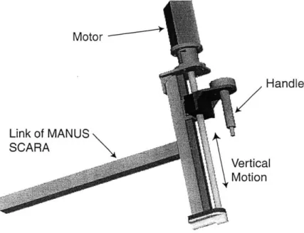
Motor Handle Link of MANUS SCARA Vertical Motion
Figure 2-1: Solid model of the new module for vertical motion.
was the bulkiness of the components needed to ensure structural rigidity with respect to the required forces.
A screw drive was considered and finally selected for the transmission. Power screws are typically fairly efficient, particularly if an effort is made to select compo-nents with minimum friction. They are also compact and available across a broad range of gear ratios. Calculations suggested that an acceptable tradeoff could be made between backdrive-ability and module mass by adjusting the travel per revolu-tion (lead) of the screw (effectively changing the gear ratio).
2.3
Screw-Driven Design
The final design chosen for development consists of a screw-driven module mounted in place of the handle on a robot similar to MIT-MANUS. A solid model of the design is shown in Figure 2-1.
A servomotor is mounted at the top of the module and rotates the screw. The turning of the screw results in vertical motion of the nut, which is mounted to a linear bearing. The bearing system is designed so that the bearing takes the undesired side
forces and torques to which the nut is subject. The handle, the interface to the patient, is mounted to the nut. If the system is driven from the motor side, the turning of the motor produces vertical motion of the handle. If it is driven from the patient side, the movement of the handle by the patient turns the screw which in turn rotates the motor.
By far the most critical parameter of a design of this type is the screw lead. A smaller lead provides greater mechanical advantage in driving from the motor side, and therefore permits a smaller actuator and a smaller planar impedance. However, a shorter lead also increases the inertia and friction reflected to the endpoint, and increases impedance in the vertical direction. Based on a desire to minimize the re-flected vertical inertia and friction as well as the planar inertia, a lead of 0.01905 m (0.75 in) per revolution was selected. Preliminary calculation suggested that the motor required for such a lead would result in a system with endpoint mass approxi-mately equal in the horizontal plane and the vertical direction, and with reasonably low friction.
A more specific description of the key hardware components is found in the next chapter, along with a detailed description of how the system works in hardware and software.
Chapter 3
System Operation
This chapter provides a specific description of how the screw-driven therapy robot module works. The understanding that this chapter strives to impart to the reader is essential in interpreting the information provided in the remaining chapters, as all data presented was gathered on the system described here.
The first section of this chapter provides a discussion of the major hardware com-ponents, their essential features, and their interaction. This includes some discussion of modifications to the original design and suggestions for changes in future versions. The second section discusses the key points relating to the structure of the soft-ware used to control the device. An understanding of the softsoft-ware proves critical in understanding the results in Chapter 4.
The final section of this chapter provides a simple description of how the system operates as a whole.
3.1
Hardware Overview
3.1.1
Rollnut
The most critical component of the module drivetrain is the screw and nut transmis-sion. The lead was selected to be 0.01905 m (0.75 in) per revolution as described in the previous chapter. Given a specific lead, it became most essential to design
the screw package for minimum friction. The effect of greater friction on the forces required to drive the unit are more thoroughly discussed in Chapter 5, but it is fairly obvious from equation 2.3 that minimizing friction is always helpful in minimizing impedance.
Several designs for low-friction screw transmissions were considered. Primarily these included plastic lead screws, ball screws, and roller screws. Plastic lead screws rely on pure sliding contact and therefore offer fairly consistent performance. Special coatings are available to reduce friction, and efficiency numbers are often impressive. In fact, some manufacturers claim efficiencies as high as 50-80% for screw assemblies of approximately the correct dimensions [21].
Because they theoretically do not rely on sliding contact, ball and roller screws offer superior friction characteristics to even the best plastic lead screws. Ball screws are widely used in machinery but are subject to inconsistencies due to the rubbing of balls against one another. Many of the consistency problems can be removed by adding a preload, but this preload increases the friction force. Ball screw manufac-turers routinely boast of efficiencies over 90% [13].
Roller screws are less common and generally more expensive than either plastic lead screws or ball screws. Several different designs are available; many of these still contain some sliding elements. Roller screws generally also offer extremely high efficiencies. Some roller screw manufacturers focus on their ability to create designs with extremely high load ratings and speed capabilities, especially as compared with ball screws [13]. In fact, much of the power screw industry is aimed toward these goals, which do not necessarily match the goals of a therapy robot.
Selection of the proper screw drive was aided through some realizations about the application. Unlike many machinery applications where power screws are typically used, this device does not require extremely tight position tolerances, nor does it require very large forces, or even particularly high speed. Instead the emphasis is on minimizing friction, even at the expense of position or force capabilities to some extent. Thus a screw that offers theoretically full rolling contact, with no sliding parts, is ideal.
Figure 3-1: Screw/nut interface of a Rollnut.
The prototype of the therapy robot uses a custom version of such a screw, called a Rollnut and manufactured by Norco, Inc. Figure 3-1 shows an illustration of the screw/nut interface. The nut is actually a carriage that holds two conical rollers. These rollers rotate freely in ball bearings about an axis perpendicular to that of the screw. The rollers ride in a precision track that is cut into the screw. The nut carriage has needle roller bearings at the top and bottom around the screw itself. The contact between these bearings and the screw is theoretically the only sliding contact as the nut moves up and down the screw, and this sliding is a minimal component of the motion. The Rollnut comes very close to offering pure rolling, and as such offers the lowest friction of any commercial screw product known to the author.
To have a package capable of supporting the desired load, a screw 15.875 mm (0.625 in) in diameter was selected. This system should be able to bear at least a 222 N (50 lb) load, clearly sufficient for this application. Figure 3-2 shows a photograph of the screw and nut package.
Though specific technical data about the roller package is unavailable, some mea-surements were made to determine the approximate dimensions. The outer shaft diameter is 15.875 mm (0.625 in). The inner shaft diameter, where the full thread
Figure 3-2: Rollnut assembly.
depth is removed, is about 12.7 mm (0.5 in). The width of the groove in which the roller rides is 3.0 mm (0.1185 in) at the thread ID and 4.0 mm (0.1575 in) at the thread OD. Thus if the roller is assumed to contact the screw primarily along the center of the thread surface, the effective screw diameter is 14.2875 mm (0.5625 in) and the effective roller diameter is 3.5 mm (0.1378 in).
3.1.2
Linear Bearing
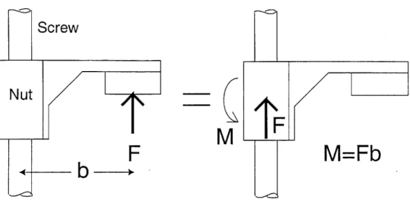
For several reasons it is important to keep the screw and nut isolated from most side loads. The handle is connected to the nut, and it is desired that forces in the vertical direction be transmitted to the nut as completely as possible, while forces in other directions be transmitted to the structure of the SCARA linkage to effect the desired planar movements. It is important to recall that side forces are fully expected in this design, as they will be used to affect movement in the plane. Furthermore there are likely to be torques acting on the handle, as the environment is unpredictable. It is simple to see that a vertical force, applied at the handle 77.85 mm (3.065 in) away from the center of the nut, will produce both a force and a torque at the nut. This
Screw
Nut
--M
F
F
M=Fb
Figure 3-3: A force at the handle induces a reaction force and a reaction torque at the nut and bearing.
simple 'beam' problem is illustrated in Figure 3-3. The distance from the center of the screw to the center of the handle acts as a moment arm and converts any forces that do not pass through the center of the nut into forces and torques at the nut.
If the nut is subjected to significant side loads and torques, this could be detri-mental in terms of wear. Perhaps more significantly, substantial changes in loading could lead to changes in the friction forces in the nut through changes in the normal force. Thus the nut should be isolated from side loads and torques, while allowed to see the full vertical load.
The solution to this problem used in the design is a linear bearing. A BM15 rail and ball carriage system from Schneeberger was selected. The bearing is shown in Figure 3-4. It uses a recirculating ball design and includes wipers on the ends to keep the ball guidance system from becoming contaminated. The robot design is such that the bearing is placed as close as possible to the center of the nut. Thus any angular displacements at the bearing (any displacements will be extremely small) are not substantially amplified and do not allow any forces to reach the nut/screw interface. The center of the nut is only 14.351 mm (0.565 in) from the mounting surface of
Figure 3-4: Linear ball bearing, rail and carriage.
the bearing. The bearing has stated loading capacities of at least 9000 N in force and a minimum of 67 Nm in torsion. The loads to be used in this application are a miniscule fraction of these capacities, and should not affect the bearing at all.
3.1.3 Mounting Support
To transmit force from the bearing to the SCARA, a simple mounting support beam was designed. This beam was designed to be stiff enough to avoid significant bending even if 222 N (50 lb) of force was applied horizontally at the extremes of the screw. Part of the back of the support is cut away to reduce weight.
If the screw were to provide 0.46 m (18 in) of travel as originally planned, the support beam would have had to be extremely bulky and heavy. To keep weight down, it was decided to limit the travel of the screw to about 0.36 m (14 in). A photograph of the mounting support beam is shown in Figure 3-5.
Figure 3-5: Structural support/mount piece.
3.1.4
Flexible Coupling
The motor output shaft is connected to the screw shaft through a Helical Beam Coupling. This type of coupling is extremely stiff in torsion along the shaft axes, so as not to introduce resonance problems. The coupling is flexible with respect to torques about the other two axes, however, so as to alleviate the problems due to slight misalignment between the two shafts. A photograph of the coupling is shown in Figure 3-6. The coupling used can transmit up to 3.95 Nm (35 inxlb) of torque and is made of black anodized aluminum.
3.1.5 Alignment Difficulties
The screw system, as originally designed, is inherently overconstrained. The screw shaft is guided by a ball bearing at the top, mounted to a rigid bore, and by a needle roller bearing at the bottom, also mounted to a rigid bore. The ball bearing at the top locates the shaft in all three axes, while the needle roller bearing locates the shaft
axis of rotation but allows play in the axial direction. The linear bearing attached to the nut results in a third point attempting to locate the rotational shaft axis. This
Figure 3-6: Helical beam coupling joining motor shaft to screw.
system is subject to classic problems of overconstraint.
Without extremely precise alignment, this overconstraint is likely to cause bind-ing. During prototype assembly, repeated attempts were made to align the system carefully. Careful thought led to investigation of potential sources of binding. The potential problems, their sources, and efforts to evaluate the likelihood of each prob-lem are shown in Figure 3-7. Measurements were made on a coordinate measuring machine, and the mountings were carefully shimmed to attempt to find the correct relative orientations of the parts. Figure 3.1.5 shows the top mounting bracket, that locates the top bearing bore, connected to the mounting support beam with shims in an attempt to achieve better alignment.
Despite repeated efforts to adequately align the system, binding was still an insur-mountable problem. It also became obvious that if the system were ever disassembled, it would be extremely difficult to realign it to get it working again.
Because small errors in position are tolerable for this application, the possibility of adding some compliance to one or more of the bearings was appealing. It is disadvantageous to add compliance to the mounting of the nut to the linear bearing, as this forces the nut to bear side loads (see section on linear bearing). Instead it
Problem : Screw / Nut is fighter Overconstrained System Problems with just 2 end / in some places, looser in others Problems
bearings and screw shaft
Screw can't rotate Nut causes
properly in interference in
mountingscrew motion
Top / bottom Screw is /Rail
riot exactly
bearings are significantly parallel to screw Rail, as it is mounted, Nut / screw Screw is eccentric, nut misaligned eccentric centerline is not straight interface changes rides straight
Don't see any real problems Screw eccentricity is -0.001" without the nut, which is a third I The rail is straight and and likely explains the relatively
bearing and overconstrains the true to within 0.0002" small friction felt at the frequency
system. of screw rotation.
Because: Bottom bearing can Misaligned in Misaligned in
float before tightening into proper / y direction 'x' direction
location One or both nut Screw thread
Screw eccentricity -0.001" (T) (S) rollers not quite errors drive nut perpendicular to into undesired
Distance from screw to Distance from screw screw position M rail In 'y is different by to rail in x' differed
-0.007" from top to by -0.005" from top Extremely difficult to This is nearly impossible to Corrected by opening Corrected with shims measure, but this problem measure, but remains a top mounting holes to seems unlikely because it possibility
to desired postn. would produce problems
float tat the frequency of the
rollers rotation -unknown,
(5) -for separation -refers to the effect this problem would be expected to have on a loosened nut with respect but very fast
to its bearing, driven by the screw -meaning, the nut would want to separate from its bearing + rail if not connected (T) -for twisting -similarly, the nut would want to rotate or twist (about x-axis) f not connected to its bearing and
rail, in order to conform best to where the screw drives it
Figure 3-7: Summary of potential sources of binding in the screw assembly. Each potential problem area is investigated, and measurements are reported.
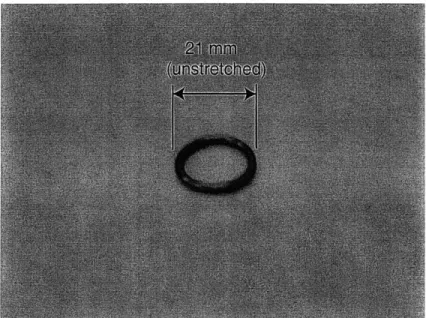
Figure 3-8: Grommet used to provide compliance in top bearing mounting.
was decided to introduce compliance at the top bearing mounting. Thus as the nut moves up and down, the screw essentially pivots about the bottom bearing into the position of least resistance, minimizing binding.
Introducing compliance to the assembly also introduces the risk of dynamic reso-nance problems. Appendix A contains an analysis of the risks of encountering such a resonance. The conclusion of this analysis is that it is important to maintain some minimum stiffness in the mounting to avoid the possibility of exciting a resonant mode with any of the driving frequencies of the system traveling at a reasonable speed.
The top bearing bore was enlarged to permit the addition of a compliant member. A rubber grommet like that shown in Figure 3-8 was added that fit snugly around the bearing and into the enlarged bore. This significantly alleviated the binding problems.
The idea of a compliant mounting seems like an excellent one for this design, and warrants further study for additional versions of the module. Perhaps compliance should be introduced at both the top and bottom bearings? More careful analysis should be done to select a proper compliance and to be sure of the actual compliance in use.