ORIGINAL PAPER
Bubble cell for magnetic bead trapping
in capillary electrophoresis
Anne-Laure Gassner&Gaëlle Proczek&
Hubert H. Girault
Received: 27 June 2011 / Revised: 2 September 2011 / Accepted: 5 September 2011 / Published online: 1 October 2011 # Springer-Verlag 2011
Abstract A bubble cell capillary classically used to extend the optical path length for UV–vis detection is employed here to trap magnetic beads. With this system, a large amount of beads can be captured without inducing a strong pressure drop, as it is the case with magnetic beads trapped in a standard capillary, thereby having less effect on the experimental conditions. Using numerical simulations and microscopic visualizations, the capture of beads inside a bubble cell was investigated with two magnet configura-tions. Pressure-driven and electro-osmotic flow velocities were measured for different amounts of protein-A-coated beads or C18-functionalized beads (RPC-18). Solid-phase extraction of a model antibody on protein-A beads and preconcentration of fluorescein on RPC-18 beads were performed as proof of concept experiments.
Keywords Magnetic particle . Bubble cell . Solid-phase extraction . Numerical simulation . Finite element method
Introduction
Capillary electrophoresis (CE) is a widely used technique providing fast separations with high resolution and
requir-ing small sample volumes. However, one major limitation is its poor sensitivity compared to liquid chromatography techniques due to the short detection path length [1]. To overcome this limitation, improvements in UV detection were proposed using longer optical path lengths with a Z-/ U-shaped or a bubble detection cell. More sensitive detection methods, such as laser-induced fluorescence or mass spectrometry are also frequently used [2,3]. Alterna-tive strategies consist in preconcentrating the analyte before CE separation, either by electrophoretic stacking or by solid-phase extraction (SPE) [3–5]. In stacking methods, the volume of the sample must be lower than the total capillary volume [6]. In SPE, a large sample volume can be pumped to extract the target analyte by adsorption on the column, followed by elution with a small liquid volume yielding high preconcentration factors [6]. For in-line SPE, the extraction column can take various forms, such as an open-tubular capillary coated with the SPE sorbent, a monolith or a packed bed of beads retained by frits, tube constrictions, or a magnetic field [7, 8]. 3D phases offer higher binding capacities than open-tubular-coated capillar-ies. Moreover, the diffusion pathway is significantly reduced, improving interactions between the analyte and the sorbent. Nevertheless, 3D phases have some drawbacks. Packed beds of non-magnetic beads require frits to retain the beads and can lead to increased backpressure, air bubbles, longer analysis times, and irreproducible electro-osmotic flows (EOFs) [9]. Monoliths overcome these problems, but their synthesis remains complex and requires a technical expertise [10].
As a valuable alternative, magnetic beads (MB) are easily manipulated using permanent magnets or electromagnets and have a well-developed surface chemistry [11,12]. Moreover, the beads can be replaced between experiments, minimizing the problems linked to cross-contamination. They have found
Anne-Laure Gassner and Gaëlle Proczek have contributed equally to this work.
Electronic supplementary material The online version of this article (doi:10.1007/s00216-011-5417-1) contains supplementary material, which is available to authorized users.
A.-L. Gassner
:
G. Proczek:
H. H. Girault (*) Laboratoire d’Electrochimie Physique et Analytique, Ecole Polytechnique Fédérale de Lausanne, EPFL SB ISIC LEPA, Station 6,1015 Lausanne, Switzerland e-mail: [email protected] DOI 10.1007/s00216-011-5417-1
a wide range of applications, such as, magnetic transport, labels for detection, mixing, cell manipulation and separation, DNA purification, catalysis, or on-chip DNA electrophoresis [13]. As previously introduced, they were also used as a solid phase to perform protein immunocapture [14] and epitope mapping of allergens [15], on-line preconcentration of low-density lipoproteins [16], and in-line extraction with octadecylsilane-functionalized beads [17], on-chip enzymatic digestion [18,19], and immunoassays [20–26].
Like a packed bed of non-magnetic beads, a magnetic plug can induce a decrease in the flow velocity when the fluid is driven at a constant pressure. As the amount of beads increases, this phenomenon becomes more important. It can lead to full obstruction of the capillary/microchannel or to plug breaking. For a given magnet and configuration [27], there is a maximum bead quantity that can be trapped, therefore restricting the binding capacity. In order to increase this amount and consequently the binding capacity, alternative solutions need to be developed. For example in the microchip field, bead chambers were developed by Oleschuk et al. to pack the SPE sorbent [28]. In capillary electrophoresis, in-line systems integrating a concentrator having a larger diameter than the capillary diameter were proposed [29,30].
Here, we show that a bubble cell can be used as a very convenient magnetic bead trap where a large amount of beads can be spatially immobilized without inducing a strong pressure drop, as it is the case when magnetic beads are trapped in a standard capillary. In the case of small diameter capillaries, e.g., 25μm, the capillary can be rapidly blocked as the plug size increases. Moreover, for these thin capillaries, a bubble cell provides a very efficient preconcentration tool.
Using numerical simulations, we determined the magnetic force for two different magnet configurations, namely two magnets in attraction and a ring magnet. The plug location was then corroborated by microscopic visualizations in a standard and in a bubble cell capillary. According to these results, the two magnets in attraction configuration were chosen for the capillary electrophoresis experiments. Pressure-driven flow (PDF) and EOF velocities, as well as magnetic bead amount were determined for protein-A beads. These results were confirmed by another type of beads (C18-functionalized beads (RPC-18)). Finally, two applications were performed to exemplify the use of the bubble cell, namely SPE of a model antibody on protein-A beads and preconcentration of fluorescein on RPC-18 beads.
Materials and methods
Numerical model and parameters
Numerical simulations, based on the finite element method, were carried out with the commercial software Flux-Expert™
(Astek Rhône-Alpes, Grenoble, France) on a Mac Pro with Ubuntu Linux 8.04 operating system. A 2D and an axisym-metrical problem were studied. The model was already described in previous studies [27, 31]. More detail is given in the Electronic supplementary material (ESM).
The following assumptions are made: (a) magnetostatic conditions (∂B/∂t=0 with B being the magnetic induction and no external source of electric or magnetic field), (b) homogeneous media (magnetic permeability μ uniform in every domain), (c) air box big enough for not perturbing the magnetic field distribution, (d) constant magnetic susceptibil-ity of the particles and magnetic moment assumed to be unsaturated, (e) static particle solution in the microchannel (no flow), (f) particles have no influence on the magnetic field, and (g) interactions between particles are not considered.
The numerical parameters are:B0=±1.3 (T),χ (magnetic
susceptibility) =1 (−) and r (bead radius)=500 (nm). Chemicals
Rabbit antibovine β-lactoglobulin polyclonal antibody (1 mg ml−1) was obtained from Gene Tex (Irvine, USA). Acetic acid (99.5%), benzyl alcohol, and fluorescein sodium were supplied by Fluka (Buchs, Switzerland). Ammonium acetate (98%) was from Merck (Darmstadt, Germany). Trifluoroacetic acid was purchased from Acros (Chemie Brunschwig AG, Basel, Switzerland). Acetonitrile and thiourea were obtained from Riedel-de-Haën (Seelze, Germany). All solutions were prepared with water pro-duced by an alpha Q Millipore System (Zug, Switzerland). Fused-silica capillaries (50/375 μm, i.d./o.d.) were obtained from BGB Analytik AG (Böckten, Switzerland) and Extended Light Path (Bubble Cell) Bare Fused-Silica Capillaries (50/375μm, i.d./o.d.) from Agilent. Before first use, the capillaries were conditioned by flushing 1 M NaOH, 0.1 M NaOH, and water for 10 min each. Protein-A-coated superparamagnetic beads (300 nm in diameter) were purchased from Ademtech (Pessac, France) and RPC-18 (1 μm in diameter) Dynabeads from Invitrogen. The protein-A bead suspensions were sonicated and diluted 20 times in water. The RPC-18 magnetic beads were diluted ten times, washed three times with 0.1% TFA, and then resuspended in ACN/H2O (10:90).
The permanent magnets are NdFeB disks at 4 mm in diameter and 1.5 mm thick (Supermagnete, Switzerland). Three of them were piled up to increase the magnetic force. The drilled disk magnets are NdFeB, 10 mm in diameter and 1 mm thick (Supermagnete, Switzerland). They are all magnetized in their smallest dimension, with a magnetic remanence of 1.32–1.37 T for the 4 mm in diameter disks and 1.17–1.21 T for the 10 mm. For the CE experiments, a small homemade Plexiglas cube (6 mm side) was machined on each side to insert magnets 4 mm in diameter with 1 mm
spacing between them. The magnets are in attraction configuration. A channel was drilled between the magnets to allow the insertion of the capillary (ESM).
Imaging of plug formation
A PACE MDQ system (Beckman-Coulter, Nyon, Switzerland) equipped with a photo-DAD and an autosampler was used in pressure mode for solution delivery. The observation was carried out with a microscope Axiovert 200 (Carl Zeiss, Göttingen, Germany) and a CCD-IRIS camera (Sony, Tokyo, Japan). A bubble cell capillary 50μm (i.d.) and 104 cm long was used. A standard capillary with the same dimensions was used for comparison. Two disk magnets 4 mm in diameter were placed in attraction configuration in a Plexiglas holder with 1 mm spacing between them. Ten drilled disk magnets 10 mm in diameter were piled up to form a larger magnet and the capillary was inserted inside the hole (ESM). The magnets were set in place before flowing the MB through the capillary. Determination of the flow velocities and peak areas The magnetic beads were always loaded at a constant pressure of 30 mbar for different durations in a 33-cm long capillary. To determine the PDF velocity, the capillary was rinsed with ammonium acetate 100 mM (pH 8). A plug of water was then injected, and the time required to attain the detector applying 30 mbar was measured. Finally, a flushing pressure of 8 bars was applied to remove the beads, and the area and height of the peak obtained was determined and used as an indicator of the amount of beads trapped. In the case of the RPC-18 beads, thiourea was used instead of water and ACN/H2O (10:90)
replaced ammonium acetate.
The procedure for the determination of the EOF was similar. The beads were loaded and trapped by constantly applying 30 mbar. The capillary was rinsed with ammonium acetate at 25 mM (pH 8). A short plug of benzyl alcohol (BA) was injected. A 7.5-kV voltage was applied, and the time necessary for BA to reach the detector was measured. The final flushing step for the determination of the MB peak area is the same as previously explained.
The experiments were carried out with a HP3DCE instrument (Agilent Technologies, Waldbronn, Germany) equipped with a diode array UV detector, an autosampler and a power supply able to deliver up to 30 kV. Data acquisition and processing were performed using HP Chemstation software.
Procedure for the antibody extraction and fluorescein preconcentration
The procedure was adapted from Chen et al. [22]. The capillaries (50/375 μm i.d./o.d.) have a 26.5-cm effective
length and a 35-cm total length. Protein-A-coated MB were trapped in the capillary as a support for antibovine β-lactoglobulin polyclonal antibody (30 mbar for 3, 5, 10, or 15 min). After binding the antibody on the beads (30 mbar for 5 min), the capillary was rinsed with ammonium acetate 100 mM (30 mbar). Acidic conditions were used to dissociate the antibody from the beads, and it was then brought to the detector by applying a 15-kV voltage.
For the fluorescein preconcentration experiment, a standard fluorescein solution (10 mg l−1 in ACN/H2O
(10:90), pH 3) was injected for a given time after the trapping of the RPC-18 beads. After adsorption and rinsing, it was eluted by flowing an ACN/H2O solution (50:50).
The injection sequence was the following: bead injection (30 mbar for 5 min), fluorescein injection (30 mbar, variable time), washing ACN/H2O (10:90; 30 mbar for
5 min), elution ACN/H2O (50:50; 30 mbar). All the
experiments were performed with the Agilent instrument described in the previous section.
Results and discussion Magnet configuration
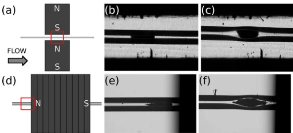
Numerical simulations were carried out to optimize the positioning of the bubble cell with respect to the magnets. Two magnet configurations were studied: the first geometry consists in two magnets placed in attraction configuration with spacing of 1 mm, the magnetization being perpendic-ular to the flow direction. The second geometry includes a ring magnet, which is a disk magnet drilled along its magnetization axis to slide the capillary through. The magnetization is therefore parallel to the flow direction. In the first case, the bubble is placed between the magnets, whereas in the second it is placed just before the magnet. The two configurations are illustrated in Fig. 1a, d.
Figure2shows the isovalues of the magnetic inductionB and the magnetic force F calculated on the capillary symmetry axis for the two configurations. On the left pictures, it can be observed that, inside the capillary, B varies rapidly near the magnets’ edges, creating a strong B gradient. The latter is required to create a magnetic force, explaining why the forces are located near the edges. With the two magnets in attraction (Fig. 2b), a positive force on the left side and negative on the right focus the beads towards the magnet center. With the axisymmetrical geom-etry (Fig. 2d), a negative force is present just before the magnet leading to bead capture at this location. Like in the attraction situation, a positive force followed by a negative one is present inside the magnet. It is thus possible to form two plugs with a ring magnet: one before the magnet and another one inside it, if the flow rate is adequately chosen.
Microscopic imaging of the plug formation was carried out to confirm the predictions of the numerical simulations. Figure1 presents the plugs obtained with the two types of magnets with a standard (b, e) and a bubble cell (c, f)
capillary. The flow was stopped to take the pictures that show that beads can be precisely trapped inside the bubble cell with both magnet configurations. However, magnetic beads form self-assembled structures that align along the
Fig. 1 Microscopic visualizations of MB plugs with two magnets in attraction having magnetization perpendicular to the capillary (a–c) and with a ring magnet having magnetization parallel to the capillary (d–f). The red squares indicate the location of the pictures. A standard
capillary (b, e) and a bubble cell capillary (c, f) are used. Conditions— protein-A beads, 300 nm in diameter (b, c) and RPC-18 beads, 1μm in diameter (e, f). Capillary 50μm (i.d.) and 104 cm long
Fig. 2 Isovalues of the magnetic induction and magnetic force for two magnets in attraction (a, b) and one ring magnet (c, d). The force was calculated for a bead radius=500 nm andB0=1.3 T (indicated by
arrows). The force values were taken along the capillary, on its symmetry axis. The gray surfaces show the magnet position
magnetic field lines [32]. When two magnets are placed in attraction, the main B component is perpendicular to the flow, while it is parallel to the flow with a ring magnet. This explains why the plugs of Fig.1e, f possess tails and not the plugs of Fig.1b, c. This tailed shape may pose a problem for preconcentration experiments as the plug is spread out on a longer distance.
The bubble cell factor of the capillary shown in Fig.1is 3, meaning that its diameter was locally increased from 50 to 150 μm. The shape of the bubble may be roughly approximated by an ellipsoid. By using dimensions of Fig. 1b, c, the bubble cell volume can be estimated to be about six times larger in comparison with the volume of the plug in the normal capillary, enabling the trapping of an increased amount of beads.
Although the ring magnet is easier to position, it may form two plugs. Indeed, if the beads are not totally retained by the first negative force, they will be trapped inside the magnet. This is not problematic if the elution is frontal, but otherwise having two plugs may be a problem. Moreover, the plug before the magnet has a tailed shape, being possibly a problem in non-frontal elution cases. Consequently, we chose to investigate experimentally the configuration using the two magnets in attraction.
Bubble cell characterization
Various experiments were carried out in order to character-ize trapping in a bubble cell capillary. The velocity of the PDF and EOF, as well as the amount of magnetic beads trapped were measured and compared with the values obtained with a standard capillary. Each measurement was repeated to evaluate the reproducibility.
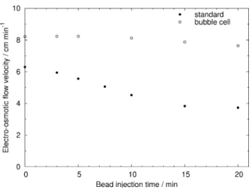
The PDF velocity was first measured at a constant applied pressure of 30 mbar. After the formation of the protein-A magnetic bead plug, a short plug of water was injected and the time required to reach the detector was measured. The corresponding flow velocity was calculated and the results are presented in Fig. 3. With a standard capillary, the flow velocity decreases rapidly as the bead injection time increases, as the plug formed impedes the flow by partially obstructing the capillary, thereby creating a pressure drop. After 20 min of bead injection, the velocity is reduced by a factor of 3, passing from 5.65 to 1.89 cm min−1. At longer injection times, it may further decrease until the capillary is blocked or until breaking of the plug, thus limiting the amount of beads possibly trapped. In contrast, the bubble cell capillary only presents a 1.3 decrease factor after 20 min of bead loading. Longer bead injection times were not investigated as the total experimental time should remain reasonable. This result is important for SPE approaches as it shows that a magnetic bead plug with a high specific surface area can be formed
within a bubble cell without altering significantly the flow rate Q. In an empty capillary, the flow rate is given by Poiseuille’s law: Q¼ pdc 4 128h @p L ð1Þ
where dcis the capillary diameter,η the fluid viscosity, L
the total capillary length, and p the pressure. This law is a limiting case of Darcy’s law describing the flow of a fluid through a porous medium.
Q¼kA h
@p
L ð2Þ
with k being the permeability of the porous medium and A the cross-sectional area to flow. In the case of an empty capillary (Poiseuille’s law), k is equal to dc
2
/32. If we assume that a bead plug can be considered as a packed bed, Darcy’s law can be used to explain the phenomenon observed with the PDF velocity. As a standard capillary has a homogeneous diameter, as soon as beads are captured, they impede the flow by decreasing the factor k, and the plug limits the flow rate. In contrast, with a bubble cell, the capillary that has a lower diameter than the bubble cell is the flow limiting element ((kA)bubble>(kA)capillary). When
the size of the plug is sufficient, the apparent diameter is smaller and this element becomes limiting. That is to say when the diameter left to the flow by the beads inside the bubble cell becomes inferior to the diameter of the rest of the capillary ((kA)bubble<(kA)capillary), the flow rate starts
decreasing like in the standard capillary. However, this model does not reflect the reality and only helps explaining what occurs inside the capillary during bead accumulation. The actual magnetic bead plug arrangement is somewhere
Fig. 3 Flow velocity induced by a 30-mbar pressure in a standard capillary (filled circles) and bubble cell capillary (empty circles) versus the magnetic bead injection time. Conditions—total/effective length, 33/24.5 cm (50μm, i.d.). Protein-A-coated MB (300 nm in diameter)
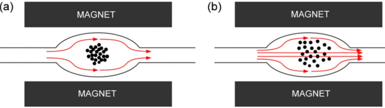
between a packed bed and a fluidized bed, meaning that the flow expands somewhat the bed compared with a static situation. Thus, even if the bubble cell is not completely filled by the beads, the liquid flows through the plug (Fig.4b) and does not only flow around it (Fig.4a).
To confirm these results, the amount of magnetic beads trapped was determined by applying a very high pressure (8 bars) to flush the beads out of the capillary. The height and area of the peak observed with the standard and the bubble cell capillaries are presented in Fig.5a, b. Both height and area increase with the bead injection time, but if a linear regression can be easily found for the peak area, the peak height is only proportional for short injection times. Indeed, as the bead amount increases, in addition to growing in height the flushing peak also broadens. The peak area is consequently a better quantitative indicator. With the standard capillary, the area reaches a plateau after roughly 15 min, whereas it continues increasing for the bubble cell capillary. This plateau is due to the fact that since increasing the injection time reduces the flow rate, fewer beads are injected in the standard capillary than in the bubble cell one, as the flow rate is lower in the first case. In addition, the larger error bar at 20 min indicates a reduced reproducibility, probably due to uncontrolled bead losses. Consequently, in a PDF a bubble cell capillary enables the trapping of a higher quantity of beads due to the locally larger volume of the bubble cell without affecting signif-icantly the flow velocity.
The influence of the EOF velocity was then studied versus the bead injection time. Different voltages were investigated, but when it was too high, magnetic beads were lost in the standard capillary. A 7.5-kV value was finally chosen, as it was the highest value giving reproduc-ible results and a relatively good plug stability in the standard capillary. The results are presented in Fig. 6. Similarly to what was observed for the PDF velocity, the EOF velocity decreases with the bead injection time. This diminution is relatively important for the standard capillary with one third of the velocity lost after 15 min, whereas for the bubble cell, the velocity decreases only very lightly.
After 15 min in the standard capillary, the velocity remains the same due to the plateau observed for the trapped bead amount. The decrease in EOF velocity may be due to the charge of the beads. Due to their respective pKa(≈3.5) and
pI (≈5.1), silanol groups from the capillary walls and
Fig. 4 Scheme of a a packed bed of beads with the liquid flowing around the plug and b plug of magnetic beads with the liquid flowing through and around the plug
Fig. 5 UV response (200 nm) corresponding to the high-pressure removal (8 bars) of the magnetically trapped MB in a standard capillary (a) and bubble cell capillary (b) versus the magnetic bead injection time. Conditions—total/effective length, 33/24.5 cm (50 μm, i.d.). Protein-A-coated MB (300 nm in diameter)
protein-A are both negatively charged at pH 8. But if the beads were to decrease the EOF due to a lower local charge density, the flow velocity should be altered with both types of capillaries when the amount of beads increases. As it is not the case with the bubble cell, the EOF velocity variation can be attributed to the tortuosity, leading the mobile solute to zigzag through the packed bed. Again, using a bubble cell capillary enables to keep a good flow rate even with high bead quantities.
To broaden the use of the bubble cell capillary, another type of beads having a larger diameter (1μm) was studied. The PDF velocity and the amount of beads trapped were determined for RPC-18 magnetic beads (Fig.7). As for the protein-A beads, the flow velocity decreases faster for the standard capillary than for the bubble cell as the bead injection time increases (Fig. 7a). At 7.5 min, the flow velocity has lost 65% of its initial value in the standard capillary while this loss is only 10% with the bubble cell. The experiments had to be stopped at 7.5 min for the standard capillary, because the plug was too unstable to produce reproducible results. Concerning the quantity of magnetic beads, the peak area increases linearly with the injection time in both cases, showing excellent correlation coefficients with high reproducibility (Fig. 7b, c). These results show that the experimental time constancy and the better stability observed with the bubble cell capillary relative to the standard one are not limited to protein-A beads but also apply to other types of beads.
Applications
Solid-phase extraction of a model IgG was carried out in both types of capillaries with different magnetic bead
injection times. The antibody is captured on the protein-A magnetic beads and then released by decreasing the pH with the injection of acetic acid inside the capillary [22].
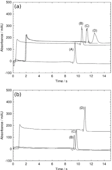
Figure8a, b show respectively the results obtained with a standard and the bubble cell capillary with bead injection times of 3 (A), 5 (B), 10 (C), and 15 (D) min. Time zero corresponds to voltage switching on. It can be seen that in both cases, the antibody peak shifts to the right with the bead injection time. The time shift is more pronounced with the standard capillary in accordance with the previous results. With 15-min bead injection (curve (D) in Fig. 8), the acetic acid zone takes more time to reach the detector (corresponding to the absorbance increase in the first minutes in the electropherogram), whereas with a small amount of beads, the zone appears before the voltage application and is consequently not observed in the electropherogram (negative time). The antibody time shift
Fig. 6 Electro-osmotic flow velocity induced by a 7.5-kV voltage in a standard capillary (filled circles) and bubble cell capillary (empty circles) versus the magnetic bead injection time. Conditions—total/ effective length, 33/24.5 cm (50 μm, i.d.). Protein-A-coated MB (300 nm in diameter)
Fig. 7 Flow velocity induced by a 30-mbar pressure in a standard capillary (filled circles) and bubble cell (empty circles) capillary versus the magnetic bead injection time (a). UV response (200 nm) corresponding to the high-pressure removal (8 bars) of the magnet-ically trapped MB in a b standard capillary and c bubble cell capillary versus the magnetic bead injection time. Conditions—total/effective length, 33/24.5 cm (50μm, i.d.). RPC-18 MB (1 μm in diameter)
is due to the presence of the bead plug that contributes to decrease both PDF and EOF velocities as discussed before. Regarding the height and the shape of the antibody peak, it can be observed that with the standard capillary, the height of the peak decreases as the bead injection time increases, while for the bubble cell capillary it increases with the injection time. For the standard capillary, it may be explained by the presence of the bead plug, which decreases the PDF velocity. Consequently, for a same antibody injection time, the amount of injected antibody decreases as the bead plug size increases, leading to smaller peak heights. But the increased length of the plug may also contribute by a less efficient preconcentration of the analyte and larger tortuosity. For the bubble cell capillary, the increasing height is attributed to the fact that when the
antibody solution passes through the plug, part of the molecules is not trapped. Increasing the size of the plug increases the number of binding sites and consequently leads to a higher antibody capture. Concerning the peak shape, there is no variation for the bubble cell capillary, but for the standard one, the shape becomes less regular and its width increases with the bead injection time.
It is important to note that the two capillaries are not equal in plug stability. Indeed, for high quantities of beads, the stability is higher with the bubble cell capillary, as with the standard one, beads are frequently lost when a 15-kV voltage is applied. This was already observed during the EOF velocity measurements explaining why a 7.5-kV value was chosen. If these experiments had to be carried out at this voltage to improve stability in the standard capillary, the experimental time would increase substantially. As a result, a bubble cell capillary is more suitable for experi-ments involving a large amount of beads. It can be noted that this simple experiment is the first step in the setting up of a full immunoassay. For a real sample like whole blood or serum, sample preparation may be necessary and non-specific interactions should be minimized by for example coating the capillary and blocking the beads. Furthermore, if specific extraction is required, such as IgG only, magnetic beads should be covalently grafted with an antibody specific for this analyte to avoid the capture of other antibodies present in the sample.
Fluorescein preconcentration experiments were then carried out to introduce another application of the bubble cell. Results are only presented for the bubble cell capillary, because of the very poor stability of the RPC-18 beads in
Fig. 8 Detection (200 nm) of antibovine ß-lactoglobulin polyclonal antibody in a a standard capillary and b bubble cell capillary. Conditions—total/effective length, 35/26.5 cm (50 μm, i.d.). Protein-A-coated MB (300 nm in diameter). Injection sequence—bead injection, 30 mbar for 3 (A), 5 (B), 10 (C) or 15 (D) min; antibody injection, 30 mbar for 5 min; washing, ammonium acetate 100 mM for 30 mbar; reverse injection, acetic acid, 10%−30 mbar for 2 min; separation, 15 kV voltage. Time zero corresponds to the voltage application
Fig. 9 UV response at 200 nm corresponding to the elution of fluorescein captured on RPC-18 MB in a bubble cell capillary versus the fluorescein injection time. Conditions—total/effective length, 33/ 24.5 cm (50 μm, i.d.). RPC-18 MB (1 μm in diameter). Injection sequence—bead injection, 30 mbar for 5 min; fluorescein injection, 30 mbar variable time; washing, ACN/H2O (10:90), 30 mbar for
the standard capillary when the elution buffer is flowed. Figure 9 shows the fluorescein peak area versus the fluorescein injection time. It can be observed that the quantity of fluorescein captured increases linearly until 5 min and then reaches a plateau corresponding to the maximum fluorescein quantity that can be fixed on the beads in these conditions. To increase the binding capacity of the beads, a higher bead amount should be trapped. However, these experiments act as proof of concept for magnetic bead trapping inside a bubble cell.
Conclusions
A bubble cell capillary was used to trap magnetic beads using the bubble cell volume as a trapping chamber. To demonstrate the advantages of this system, a comparison with a standard capillary was carried out by different methods. Numerical simulations aimed at showing the position of the magnetic forces to place the bubble cell adequately with respect to the magnets. Microscopic visualizations corroborated the predictions of the simu-lations and illustrated the accumulation of the beads inside the bubble. The PDF and EOF velocities were measured for different amounts of protein-A-coated beads or RPC-18. Finally, extraction/preconcentration experiments were achieved as proof of concept. Com-pared with a standard capillary, the bubble cell enables the capture of more beads without decreasing signifi-cantly the PDF and EOF velocity. In the case of small diameter capillaries (f.e., 25 μm), where the capillary is rapidly blocked by a bead plug, trapping a high amount of beads is essential to preconcentrate the analyte, as the sensitivity of a UV detector is limited. Moreover, the stability of the bead plug is higher with a bubble cell, as for large plugs, beads are not lost for a typical separation voltage of 15 kV, leading to a better reproducibility of the experiments. Finally, the implementation of this trapping method is simple, as the capillaries and the magnets are commercially available.
Acknowledgments The authors wish to thank the Swiss National Science Foundation for financial support, grant entitled “Supramolec-ular phases for protein adsorption” (grant no. 404740-117321). The authors also thank the “Agilent Technologies Foundation” for a research award and Dr. Stéphanie Descroix for helpful discussions.
References
1. Breadmore MC, Dawod M, Quirino JP (2011) Recent advances in enhancing the sensitivity of electrophoresis and electrochroma-tography in capillaries and microchips (2008–2010). Electropho-resis 32(1):127–148
2. Hempel G (2000) Strategies to improve the sensitivity in capillary electrophoresis for the analysis of drugs in biological fluids. Electrophoresis 21(4):691–698
3. Tempels FWA, Underberg WJM, Somsen GW, de Jong GJ (2008) Design and applications of coupled SPE-CE. Electrophoresis 29 (1):108–128
4. Saavedra L, Barbas C (2007) Chromatography-based on- and in-line pre-concentration methods in capillary electrophoresis. J Biochem Bioph Meth 70(2):289–297
5. Puig P, Borrull F, Calull M, Aguilar C (2007) Recent advances in coupling solid-phase extraction and capillary electrophoresis (SPE-CE). Trac-Trend Anal Chem 26(7):664–678
6. Ramautar R, Somsen GW, de Jong GJ (2010) Recent develop-ments in coupled SPE-CE. Electrophoresis 31(1):44–54 7. Guzman NA, Blanc T, Phillips TM (2008) Immunoaffinity
capillary electrophoresis as a powerful strategy for the quantifi-cation of low-abundance biomarkers, drugs, and metabolites in biological matrices. Electrophoresis 29(16):3259–3278
8. Augustin V, Proczek G, Dugay J, Descroix S, Hennion MC (2007) Online preconcentration using monoliths in electrochromatogra-phy capillary format and microchips. J Sep Sci 30(17):2858–2865 9. Puig P, Borrull F, Calull M, Aguilar C (2008) Sorbent preconcentra-tion procedures coupled to capillary electrophoresis for environmen-tal and biological applications. Analytica Chimica Acta 616(1):1–18 10. Peterson DS (2005) Solid supports for micro analytical systems.
Lab Chip 5(2):132–139
11. Pamme N (2006) Magnetism and microfluidics. Lab Chip 6 (1):24–38
12. Gijs MA, Lacharme F, Lehmann U (2010) Microfluidic applica-tions of magnetic particles for biological analysis and catalysis. Chem Rev 110(3):1518–1563
13. Doyle PS, Bibette J, Bancaud A, Viovy JL (2002) Self-assembled magnetic matrices for DNA separation chips. Science 295(5563):2237 14. Kaneta T, Inoue J, Koizumi M, Imasaka T (2006) On-column capture of a specific protein in capillary electrophoresis using magnetic beads. Electrophoresis 27(16):3218–3223
15. Jankovicova B, Rosnerova S, Slovakova M, Zverinova Z, Hubalek M, Hernychova L, Rehulka P, Viovy JL, Bilkova Z (2008) Epitope mapping of allergen ovalbumin using biofunctionalized magnetic beads packed in microfluidic channels. The first step towards epitope-based vaccines. J Chromatogr A 1206(1):64–71
16. Okamoto Y, Kitagawa F, Otsuka K (2007) Online concentration and affinity separation of biomolecules using multifunctional particles in capillary electrophoresis under magnetic field. Anal Chem 79(8):3041–3047
17. Tennico YH, Remcho VT (2010) In-line extraction employing functionalized magnetic particles for capillary and microchip electrophoresis. Electrophoresis 31(15):2548–2557
18. Slovakova M, Minc N, Bilkova Z, Smadja C, Faigle W, Futterer C, Taverna M, Viovy JL (2005) Use of self assembled magnetic beads for on-chip protein digestion. Lab Chip 5(9):935–942 19. Le Nel A, Minc N, Smadja C, Slovakova M, Bilkova Z, Peyrin
JM, Viovy JL, Taverna M (2008) Controlled proteolysis of normal and pathological prion protein in a microfluidic chip. Lab Chip 8 (2):294–301
20. Rashkovetsky LG, Lyubarskaya YV, Foret F, Hughes DE, Karger BL (1997) Automated microanalysis using magnetic beads with commercial capillary electrophoretic instrumentation. J Chroma-togr A 781(1–2):197–204
21. Hayes MA, Polson NA, Phayre AN, Garcia AA (2001) Flow-based microimmunoassay. Anal Chem 73:5896–5902
22. Chen HX, Busnel JM, Gassner AL, Peltre G, Zhang XX, Girault HH (2008) Capillary electrophoresis immunoassay using magnetic beads. Electrophoresis 29(16):3414–3421
23. Chen HX, Busnel JM, Peltre G, Zhang XX, Girault HH (2008) Magnetic beads based immunoaffinity capillary electrophoresis of
total serum IgE with laser-induced fluorescence detection. Anal Chem 80(24):9583–9588
24. Lacharme F, Vandevyver C, Gijs MA (2008) Full on-chip nanoliter immunoassay by geometrical magnetic trapping of nanoparticle chains. Anal Chem 80(8):2905–2910
25. Hahn YK, Jin Z, Kang JH, Oh E, Han MK, Kim HS, Jang JT, Lee JH, Cheon J, Kim SH, Park HS, Park JK (2007) Magnetophoretic immunoassay of allergen-specific IgE in an enhanced magnetic field gradient. Anal Chem 79(6):2214– 2220
26. Do J, Ahn CH (2008) A polymer lab-on-a-chip for magnetic immunoassay with on-chip sampling and detection capabilities. Lab on a Chip 8(4):542–549
27. Gassner AL, Abonnenc M, Chen HX, Morandini J, Josserand J, Rossier JS, Busnel JM, Girault HH (2009) Magnetic forces produced by rectangular permanent magnets in static micro-systems. Lab Chip 9(16):2356–2363
28. Oleschuk RD, Shultz-Lockyear LL, Ning YB, Harrison DJ (2000) Trapping of bead-based reagents within microfluidic systems: on-chip solid-phase extraction and electrochromatography. Anal Chem 72(3):585–590
29. Strausbauch MA, Landers JP, Wettstein PJ (1996) Mechanism of peptide separations by solid phase extraction capillary electro-phoresis at low pH. Anal Chem 68(2):306–314
30. Lara FJ, Lynen F, Sandra P, Garcia-Campana AM, Ales-Barrero F (2008) Evaluation of a molecularly imprinted polymer as in-line concentrator in capillary electrophoresis. Electrophoresis 29 (18):3834–3841
31. Gassner AL, Morandini J, Josserand J, Girault HH (2011) Ring magnets for magnetic beads trapping in a capillary. Analytical Methods 3(3):614–621
32. Hayes MA, Polson NA, Garcia AA (2001) Active control of dynamic supraparticle structures in microchannels. Langmuir 17 (9):2866–2871