/-z >'
An Axial Force Sensor For a Prosthetic Knee
by
Theresa V. luzzolino
Submitted to the Department of Electrical Engineering and Computer
Science in partial fulfillment of the requirements for the degrees of
Master of Engineering in Electrical Engineering and Computer Science,
Bachelor of Science in Computer Science and Electrical Engineering, and
Bachelor of Science in Mechanical Engineering
at the
MASSACHUSETTS INSTITUTE OF TECHNOLOGY
May 28, 1998
Copyright 1998, Theresa V. Iuzzolino, All rights reserved.
The author hereby grants to M.I.T. permission to reproduce and
dis-tribute publicly paper and electronic copies of this thesis and to grant
others the right to do so.
A uthor . _,... . ... ... . .... . . ... ...
Department of Electrical Engineenn
gnd
Computer Science
May 28, 1998
Certified by
...
. . . ...
-
"
...
Professor Gill Pratt
Departmentof' ectrical Fineng
and
mputer Science
S-n.
. 0
\/ - ...
;
sia
Supervisor
A ccepted by
... ...
..
...
\Frederic Morgenthaler
Chairman, Department Committee on Graduate Theses
An Axial Force Sensor For a Prosthetic Knee
by Theresa V. Iuzzolino
Submitted to the Department of Electrical Engineering and Computer Science In partial fulfillment of the requirements for the degrees of Master of Engineering in Electrical Engineering and Computer Science, Bachelor of Science in Computer Science and
Elec-trical Engineering, and Bachelor of Science in Mechanical Engineering.
May 28, 1998
Abstract
One out of every thousand people in the United States has had a limb amputated, with more than 30% of the amputations removing the knee. The MIT Leg Laboratory, in collaboration with Flex-Foot, is working on an intelligent above-knee prosthesis, requiring a light, short, and accurate axial force sensor. This thesis investigates a design proposed
by Cullen [3], using a pressure sensor inside of two capped, concentric cylinders between
which is a layer of silicone. Experiments were performed with GE's RTV 664 silicone, and the Motorola MPX5700D and MPX5999D, EG&G Model 83, and ACSI Model 7000 pressure sensors, and the Interlink Force Resisting Sensors. The design worked with the Motorola and EG&G sensors, but not reliably with the Interlink FSRs. The sensor can be reduced to 2 inches in length without much loss in stiffness. Greater accuracy and an investigation into the choice of silicones is still needed.
Thesis Supervisor: Professor Gill Pratt
Acknowledgments
This thesis is my final hurdle to graduating and leaving MIT! In my nine years here (including time off), I've made a number of friends who have supported me throughout the years, and especially this last semester as I finished up all the work I had put off until the last moment.
I am especially grateful to Gill Pratt for giving me a chance to start a new thesis
when my old one wasn't going anywhere, and for being patient with me when the work didn't go as fast as needed because I was working on US First and my classes.
I want to thank the people in the Leg Laboratory for all of their suggestions and pointers and for answering my questions even if the answer was "we haven't figured that out yet." These people are Gill Pratt, Olaf Bleck, Hugh Herr, Dan Paluska, Ari Wilkenfeld, Jerry Pratt, Mike Wittig, and Bruce Deffenbaugh.
A special thank you to Brian Gearing, a Mechanical Engineering graduate student
who, without knowing me, generously offered to spend a couple of hours running tests on the sensors on an Instron machine for me.
I'm grateful to those people who have been patient with me, to my parents who probably wondered if I'd ever leave MIT, to Karen Sollins, my advisor, who cheerfully urged me on to completing my degrees and was never disappointed when I hadn't done as much as I said I would, and to Anne Hunter who has always given good advice and cares so much about all of the students and works hard to make sure we all graduate.
A big thank you to Nick Matsakis for helping me throughout this year, especially in
these last weeks through his support and encouragement, through lessening my load by doing some of my day to day chores, and for bringing me meals during the last two weeks of my thesis. While others were living on pizza and takeout, I was dining on gourmet cui-sine.
And thanks to Danilo too, who, in the last hours, saved me a lot of time by providing the paperwork and materials I needed to finish up the thesis.
I want to especially thank everyone who stood with me through this time in prayer: Brother Nick Austriaco, Nick Matsakis, Durodami, Danilo, Andrew and Wendy, Betty, Luis, and all those in Maranatha and CF who prayed for me. By God's grace this thesis is finished, and by His grace I was able to remain cheerful until the end.
Table of contents
Abstract 2 Acknowledgments 3 Table of contents 4 List of Figures 5 Chapter 1: Introduction 6 Chapter 2: Background 7 Chapter 3: Objectives 12Axial force sensor requirements 12
Proposal for new sensor design 14
Scope of analysis, design, and testing 17
Chapter 4: Axial Force Sensor Design 18
Physical Design 18
Analysis 19
Discussion of analysis 26
Chapter 5: Prototype Design and Testing 29
First stage of testing 29
Second stage of testing 31
Results 33
Chapter 6: Concluding Remarks 43
Discussion 43
Conclusions and Recommendations for Future Investigation 44
Bibliography 45
Data Sheets and Suppliers 46
Appendix A: Motorola Data Sheets 47
Appendix B: Honeywell Data Sheets 53
Appendix C: EG&G Model 83 Data Sheets 57 Appendix D: ACSI Sensor Data Sheets and Amplifier circuit diagrams from
Model 7000 application notes 59
Appendix E: Interlink Electronics FSR Data Sheets 63
List of Figures
Figure 1: Walking cycle 8
Figure 2: Axial force sensor designed by Cullen 10 Figure 3: Axial force sensor modified by Goldfarb 11
Figure 4: Prosthesis assembly 12
Figure 5: Basic load cell design 15
Figure 6: Sensor designs 20
Figure 7: Diagram for theoretical analysis 21 Figure 8: Thin ring of silicone and effects of displacement by xd 22
Figure 9: Shear triangle 22
Figure 10: Top layer of silicone 24
Figure 11: Cross-section of optimized inner cylinder 27
Figure 12: First stage testing sensors 29
Figure 13: Mold-making stand 30
Figure 14: Stage two test sensors 31
Figure 15: Motorola MPX5999D, 2" wall height, sensor output versus force 36 Figure 16: Motorola MPX5700D, 1" wall height, sensor output versus force 37 Figure 17: Motorola MPX5700D, 2" wall height, sensor output versus force 38 Figure 18: Motorola MPX5700D, 3" wall height, sensor output versus force 39 Figure 19: EG&G Model 83, 2" wall height, sensor output versus force 40 Figure 20: Single cycle of the Motorola MPX5999D sensor 41 Figure 21: Force versus displacement curves for 1", 2", and 3" stage two sensors 42
Chapter 1: Introduction
One out of every thousand people in the United States has had a limb amputated. Many of these amputations occur in the elderly where the effects of vascular disease require removing part of the leg or foot. In order to walk again, amputees use a mechanical prosthesis to substitute for the missing portion of the limb. The human body is designed to minimize the movement of the center of mass during walking, but a simple prosthesis is unable to fully the replace the functionality of the missing limb, causing an unnatural gait
and a higher energy expenditure.
The MIT Leg Laboratory, with support from Flex-Foot Inc., is developing an intelli-gent prosthetic knee which will enable above-knee amputees (missing the foot, ankle, and knee) to have a more natural gait. The intelligent knee will determine how much torque to apply at the knee depending on how fast the person is walking and where they are in the stride cycle. To accomplish this, the control program needs to know how much weight the person is putting on the knee. The object of this thesis is to design an axial force sensor
which will be placed below the electromechanical knee joint.
Chapter 2 is a brief overview of the stride cycle followed by a discussion of the types of prostheses on the market and the axial force sensors used in some of them. Chap-ter 3 discusses the objectives for the new axial force sensor, while chapChap-ter 4 gives a theo-retical analysis of the basic sensor design and a discussion of the engineering trade-offs. Chapter 5 discusses the prototypes used for testing and the results. Chapter 6 concludes with recommendations for future research.
Chapter 2: Background
In the basic walking cycle each leg goes through two phases-the stance phase and the swing phase as shown in figure 1. In the stance phase, the leg is on the ground support-ing the weight of the body, and in the swsupport-ing phase, the foot is lifted off of the ground and the leg swings forward. The start of a step is marked by heel strike, when the heel hits the ground in front of the person. This is followed by toe-down where both the heel and the toe are touching the ground. The other leg then goes through toe-off which is the removal
of the foot from the ground, and swings forward to start the next step with a heel strike.
Experiments show that the primary role of the knee in walking is to bend during the swing phase allowing the foot to lift off of the ground so that the body's center of mass changes as little as possible. The majority of the energy needed to walk comes from the hip, not the knee, and the knee acts primarily as a damper. It turns out that damping
applied by the knee varies with the walking speed.
There are a variety of prosthetic knees currently on the market and being developed in labs. These range from a "peg leg" (no knee at all) to intelligent knees such as the Endolite Intelligent Prosthesis Plus, the Seattle Power Knee, and one being developed by the MIT Leg Laboratory. Since the knee acts primarily as a damper, many prosthetic knees are simply passive damping mechanisms. The damping coefficient is either preset or can be set manually by the user before, but not during, walking and determines the rate at which the amputee can naturally walk. Should the amputee choose to walk faster, the prosthetic leg will take too long for the heel to strike and the gait will be unnatural.
The object of the intelligent knee is to adjust the torque and damping coefficient applied by the knee in response to changes in the amputee's gait. The prosthesis needs to be able to adjust quickly to changes in the velocity of the user and unevenness in the ter-rain. The MIT Leg Laboratory is developing an intelligent knee based on research done by MIT Professor Woodie Flowers in the 1980s. The Flowers prosthesis is a programma-ble knee with a geared magnetic particle brake actuator and a SACH (solid ankle, cush-ioned heel) foot. A SACH foot has no joints in the ankle, but simulates the role of the
Right Left Right
heel heel heel
contact contact I contact
R. Step L. Step R. Step ,
length F length ' length
Cycle length (stride)
LL
1
IfAAl
$
Kid
Vght Left Left Right Right Left
eel toe- heel toe- heel
toe-ntact off contact off contact off
% 50% 100oo%
Time, percent of cycle
suppr R. Single support eDuor L. Single support
soupe
R. Stance phase r R. Swing phase
L. Swing phase 4 L. Stance phase
4-- -Cycle (stride) duration I
Time Dimensions of Walking Cycle
Figure 1: Walking cycle (from Human Walking, Inman et. al [6], page 26)
A Ri h cor C B
I
ankle's movement with a cushioned heel. The MIT Leg Laboratory, with funding from Flex-Foot, is designing a more powerful prosthesis with a direct drive magnetic particle brake and the next generation of control circuitry and software. The new design will be compact enough to allow Flex-Foot to add a flexible foot which allows rotation at the ankle joint. Because the flex-foot is taller and heavier than the SACH foot previously used, the prosthetic knee needs to be smaller and lighter than the Flowers knee. The new prosthesis will have a smaller actuator, electronics, and a shorter axial force sensor, which takes up 6 inches in the Flowers knee, nearly 1/3 of the length of the prosthesis.
The leg experiences significant bending moments during walking, yet the axial force sensor needs to measure only the force applied through the axis of the leg. The sensor must account for or get rid of the bending moment while being able to withstand it struc-turally. The axial force sensor on the Flowers knee was developed by Christopher Cullen [3] in 1984 and modified by Michael Goldfarb [4] in 1992. Cullen's design, as shown in figure 2, consists of two concentric cylinders with a silicone elastomer between them. The inner tube is capped, and a screw in the cap applies a force to a beam with a strain gauge.
In Goldfarb's design, shown in figure 3, the strain gauge is replaced by a linear mag-netic potentiometer to get rid of frictional effects and to increase accuracy since the poten-tiometer has less drift. Despite this, the sensor still exhibits hysteresis and has been off by as much as 8 pounds at low forces. The purpose of this thesis is to use Cullen's basic design to develop a force sensor which is more reliable at low forces, smaller, cheaper, and lighter.
Outer "
Cylinder
Elastomer -J Inner Cyl i nder Gauge Knee Hinge Electronics Sensing Beam , Hose Clamp Leg TubeMF
F Magneto-resistive linear potentiometerL
h.
Z
-
Aluminum Adjustable self-Slocking screw SSilicone rubberF
MChapter 3: Objectives
Axial force sensor requirements
A prosthetic knee needs to be light, compact, strong, and inexpensive. The following
requirements for the MIT Leg Laboratory's knee (not including the flex-foot) have been agreed on by Flex-Foot and the MIT Leg Laboratory. The knee must cost less than $750 to manufacture in quantities of 200 and weigh no more than 1 kg (2.2 pounds). It must be less than 30mm (1.2") from the top to the center of the knee, 200mm (7.9") from the cen-ter of the knee to the bottom, 60mm (2.36") in width (medial-lacen-teral), and 70mm (2.75") in depth (anterior-posterior). The prosthesis must be able to support an average male (200+ lbs), and must therefore withstand very large forces and bending moments. The knee must have a lifetime of 3 years under moderate use, and the battery must support 10 hours of continuous use. Since the knee is targeted at a variety of users including people who are very active and who live in different climates, it needs to operate correctly over a range of temperatures, forces, and speeds.
The knee consists of a rotary magnetic brake filled with magnetic particle fluid whose viscosity changes with the strength of the netic field going through it. The larger the mag-netic field, the higher the damping effect. The axial force sensor is attached below the knee, and the Flex-Foot is attached to the bottom of the sen-sor, as shown in figure 4. The electronics and batteries will be attached or placed inside of the knee brake or the sensor. Because the brake is magnetic, the axial force sensor must operate correctly near a magnetic field.
Leg
SParticle
Brake SensorFlex-Foot
The size requirements for the axial force Figure 4: Prosthesis assembly sensor are that it have a maximum height of
60mm (2.36") medial-laterally and 70mm (2.75") anterior-posteriorly. The knee will be regularly subject to compression forces of 1120N (2501b) and moments around 80N-m [6, pg 102], but must be able to withstand forces of 3336N (750 pounds-three times body weight) and moments up to 120N-m [6, pg 95]. The knee needs to be able to withstand tensile forces around 120N1. The knee should be very stiff, with less than 6mm (1/4" of play) at the end of a 50cm (20") foot for moments experienced during walking [3, pg 63]. This is an angle of rotation of 0.72 degrees. Normal walking speeds range from 70 to 150
steps/min [6, pg 28], so a safe range of operation is 0 to 10Hz.
Ideally, the sensor should be temperature compensated giving constant readings over a range of -20 to 120 degrees Fahrenheit. It needs to be water resistant and have a high fatigue life, and must be light and inexpensive (under $100).
Until the controller development is finished and a more accurate sensor is placed on the knee, we can only estimate the accuracy requirements. To correctly respond to the gait of the user, the controller needs to know when the foot is on the ground, especially when heel-strike and toe-off occur, and to determine when the user is putting at least a third of his body weight on the leg. Heel-strike and toe-off occur at very low forces, around 1 or 2 pounds, accompanied by a moment around 20N-m [10, figures 3,5,6][6, pg 86], so the sen-sor should be accurate to within one pound in the 0 to 5 pound range. It should also be repeatable to within one pound for each cycle in this range so that the knee can operate consistently with each step, although drift over the lifetime of the sensor could be accounted for by the controller. It is desirable, but not necessary for the sensor to measure negative forces.
The sensor will be battery powered, with its output read by a microprocessor. It therefore needs to operate on a DC voltage under 12V, have an output range between 0 and 3V, and consume little power. The microprocessor will read the output of the sensor, and, if necessary, can use a lookup table to determine the correct conversion between voltage and force, so the sensor need not be linear. In fact, a non-linear sensor whose output varies
1. Estimate the force applied by a 5 kg mass with center of mass at 50cm (20") swinging at
as the log of the force is desirable, because we need the same resolution between 1 and 10 pounds and 10 and 100 pounds.
Proposal for new sensor design
The difficulty in designing the axial force sensor is that the bending moment on the leg is very large and needs to either be measured and accounted for or prevented from reaching the force sensor.
One method of measuring the axial force is to use strain gauges to measure the strain in the metal in the leg. With gauges carefully placed at a equal distances on opposite sides of the axis of bending, the moment can be subtracted out. Strain gauges, however, require careful attachment, large amplifications, and they drift with time, although the latter could, as mentioned earlier, be compensated for in software.
Commercially available strain gauge-based load cells sell for $200-500. Those that are small and lightweight cannot withstand large bending moments. Those that can with-stand the moments are generally bulky and heavy. Either way, they are too expensive for this knee.
In the Flowers knee, the axial force is determined using the displacement between two cylinders which have a 3 inch tall thin layer of silicone between them. This allows stress to be measured with a strain gauge sensing beam in Cullen's version and axial dis-placement to be measured in Goldfarb's version. The silicone between the cylinders opposes the moment applied to the sensor so that the strain gauge sensing beam is pro-tected from the moment applied to the leg. In addition, silicone's modulus of elasticity is close to three times its shear modulus, which conveniently allows the desired axial move-ment while restricting bending.
The problem with Cullen's design is that there is a potential for frictional effects and wear due to the screw on the sensing beam. Goldfarb attempted to get rid of the friction using a linear magnetic potentiometer with a bias spring, but with movement, there is the problem of hysteresis. When energy is lost to heat in the loading cycle, the sensor does
not return to its original position. Voltages measured after the prosthesis is compressed and released differ from those taken after it is pulled and released, resulting in a reading that has been off by up to 8 pounds. The difference in these readings makes it difficult to determine when heel-strike and toe-off occur.
For this thesis, we use Cullen's basic
Silicone Sensor
design, but instead of using strain gauges glued to a beam, we measure the force on the leg by cap-ping the top of both tubes and embedding a
pres-sure or force sensor in a layer of silicone between - i
them, as shown in figure 5. I I
I I
Survey of sensors on the market
A survey of the pressure and force sensors I I on the market revealed a large number of
expen-sive strain gauge based sensors, and a few other Figure 5: Axial force sensor design sensor technologies such as thick film, thin film,
piezoresistive sensors, and force sensing resistors. We found four companies which man-ufacture pressure sensors which sell in small quantities for under $100: Motorola Semi-conductor at $20, EG&G IC Sensors at $97, Honeywell/Micro Switch at $65, and Advanced Custom Sensors, Inc., for $45. We also experimented with force sensing resis-tors made by Interlink Electronics which are less than $10 each.
Motorola manufactures a series of semiconductor-based piezoresistive transducers where the piezoresistive material is laid on a small diaphragm that bends under pressure (see Appendix A for data sheets and diagrams). Piezoresistive materials change resistance under stress. The sensor has a chip housed in a silicon package with the back side of the chip exposed to air through a small vent, and the front side covered with a protective fluo-rosilicone gel. In order to use these sensors, the metal caps need to be removed and a small hole is placed in the top of the outer cylinder of the axial force sensor to leave the vent open to the air. We chose to experiment with Motorola's signal-conditioned, differ-ential sensors with pressure limits of 1000KPa (150psi) for the MPX5999D and 700KPa
(100psi) for the MPX5700D. The signal-conditioned series is temperature compensated and calibrated, and the output has been amplified to give values between 0 and 5V. The differential chips measure gauge pressure. All of Motorola's pressure sensors are designed for air only since the fluorosilicone gel is water-permeable which could allow the thin leads from the chip to the pins to degrade. Attempts to use them in water have appar-ently been successful when the fluorosilicone gel was covered with another protective gel
[18].
EG&G and Honeywell (Micro Switch division) also make piezoresistive semicon-ductor sensors. The Microswitch 40PC series has a cap with a port for attaching an air hose (see Appendix B for data sheets), and is similar to Motorola's pressure sensor with two small air holes in the back. Attempts to embed this chip in silicone failed because the chip is attached to the port, and taking off the port/metal cap tore the chip out as well.
EG&G IC Sensors makes a series of harsh environment sensors. The Model 83 is a closed metal container with the piezoresistive sensor in a liquid which transmits the force (see Appendix C for data sheets). The Model 83 is also temperature compensated using a ceramic chip with laser-trimmed resistors designed to compensate the output of each par-ticular sensor. The sensor measures gauge pressure against a sealed cavity at atmospheric pressure.
Advanced Custom Sensors, Inc. (ACSI) sells strain gauge-based sensors, but uses a vacuum deposited thin film strain gauge instead of the traditional strain gauge attached by epoxy (see Appendix D for data sheets). The process allows them to make thinner strain gauge grid lines, and to sell their sensor for one fifth of the price of other strain gauge sen-sors. The Model 7000 is designed for use in hydraulic lines and is enclosed in a metal dia-phragm. Like the EG&G Model 83, this model measures the pressure difference against a sealed atmospheric pressure reference cavity.
Another sensor with which we experimented is Interlink's Force Sensing Resistor (FSR). FSR's are thin plastic sensors with an interdigitating circuit printed on a plastic film and a second layer with a resistive substrate (see Appendix E for partial data sheets).
Under pressure, the films have a higher area of overlap which lowers the resistance. With these sensors, the log of the force varies inversely with the log of the resistance, a property that is perfect for our application. However, the sensors are only accurate to within 10%, and are not designed for precision measurements but are used as switches for touch con-trol in electronic devices. We evaluated their use as an on-off switch to determine when heel-down and toe-off occur. These sensors come in a variety of sizes, all with the same force versus resistance curve. We used the small round sensors of sizes 0.2" and 0.5". The tail of the sensor must be exposed to atmospheric pressure since the sensor is measur-ing gauge pressure.
Scope of analysis, design, and testing
The development of the axial force sensor can be separated into two parts: design issues for a working sensor and manufacturing issues. We will look into some of the design issues, but not the manufacturing issues. Optimization of weight and space is a concern in design as well as manufacturing, and we will consider these in the design phase, but we will not attempt to find the optimal balance between cost, size, strength, use-ful life, and weight here. Temperature compensation is already done in most of the sen-sors and is a common technique so we will not address it, either.
The goal of the analysis is to understand the trade-offs in weight, size, strength and rigidity. The goal of the testing is to determine whether the overall design is suitable for our needs and how the sensors perform.
Chapter 4: Axial Force Sensor Design
Physical Design
Our design criteria are that the sensor be short, functional, lightweight, less than
2.3" in diameter, and have the prosthetics industry's standard four hole connector (four
1/4" holes on a circle of radius 2" at 90 degrees apart) on both the top and bottom of the sensor. The top of the sensor will be attached to the rotary knee actuator and may later be incorporated as one piece with the Flex-Foot will be attached to the bottom of the sensor.
Our goal is to transmit the axial force from the leg to the pressure or force sensor inside of the axial force sensor. Since the less expensive sensors cannot support the bend-ing moment by themselves (and in some cases the weight either), the sensor must be embedded in a support structure. This structure acts like a spring in parallel, supporting part of the force along with the pressure sensor. If this support were a closed cylindrical container made out of aluminum or carbon fiber, a material rigid enough to withstand large bending moments would not transmit much of the force because it would act like a very strong spring in parallel. We therefore need a design that withstands large bending moments while transmitting large forces. This is the solution that Cullen proposed-the elastomer acts as a soft spring while the rigid cylinders support the bending moment. The pressure applied to the sensor is therefore proportional to the area of the tube as
F F A =ir2
The elastomer needs to have as low of a hysteresis as possible, and silicone is a log-ical choice. The silicone we chose was GE's mold-making RTV664. It has a durometer of 60 on the Shore A scale, and is a two part, platinum cure silicone which allows it to cure without exposure to air within 24 hours. A feature of the mold-making silicone is that it does not adhere to anything without a primer so as long as only the desired areas are painted with primer, the remainder of the silicone can be peeled away, allowing significant leeway in how the sensors are made.
We can fill the upper portion of the sensor with something other than silicone. If we use oil or water, there is a potential for leakage and it would make a mess if the sensor breaks. Furthermore, the Motorola sensors are not designed for either oil or water since the fluorosilicone is water permeable and water can damage the sensor. If the volume is filled with air, then temperature changes will change affect the pressure in the tube and change the reading. Since the material in the top needs to be soft enough transmit pressure evenly, an elastomer can be used. This elastomer does not need to be the same as the one on the sides.
Even though the pressure at a point should be the same in all directions, it makes the most sense to align the sensor so that the plane of the sensing surface is perpendicular to the axis of the force. Also, since there will still be some angular displacement, the sensor should be centered in the tube so that the pressure on the sensor has a minimal bending moment component. The sensor should be attached to one of the horizontal surfaces so that it doesn't move when the silicone is applied. Open gauge sensors such as the Motor-ola sensors will need an air hole as well. The EG&G sensor has a 9/16"-32 thread on it which allows it to be mounted through the wall. The electronics, however, come out of the back of the sensor, so it needs to be mounted through the inner cylinder, with a hole left for the wires to come out of the side. Sealed gauge pressure sensors can be completely enclosed with the wires coming out of the side of the outer cylinder.
We now have our basic design as shown in figure 6, and will proceed to analyze the effects of the geometry on the angular displacement, vertical displacement, strength, and weight.
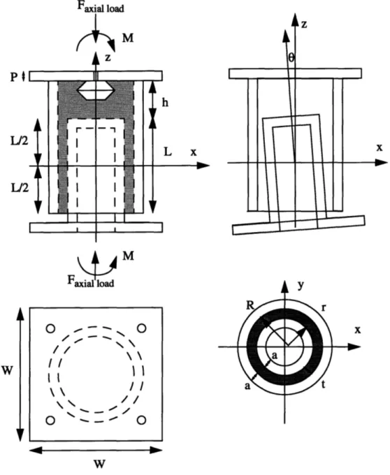
Analysis
In the analysis that follows, refer to the picture in figure 7. R is the outer diameter of the layer of silicone on the side, and r is the inner diameter of the silicone. The thickness of this layer is sometimes referred to as t where t = R - r. The height of the thin silicone wall between the cylinders is L. The thickness of the silicone plug on top is h and is assumed to be solid silicone (no sensor present). The thickness of the aluminum tubing is
y-II II I. i
I I
Open air gauge sensors (Motorola)
I I I I Interlink sensors O O Top surface-// II SIi \\II \\ il Top surface
Sealed gauge sensors (ASCI)
i-Thin cylinder of silicone EG&G sensor O O II O O Bottom surface Figure 6: Sensor designsaxis and the force F along the z-axis. The angle of rotation,
E,
is assumed to be about the origin which is at the center of the thin cylinder of silicone. The modulus of elasticity is E, and the shear modulus is G. The thickness of the top and bottom square plates is P, with WFaxial load M
4z
PI L/2 1/2 L/2M
Faxial load O -- O // \\ I Io
r--h L x -NoFigure 7: Diagram for theoretical analysis as the width of each edge.
Bending moment versus angle
We will first analyze how the bending moment affects the angle of rotation. We can assume that the silicone is incompressible,1 and therefore has constant volume. We will also assume that the silicone has a linear elastic region although this is almost certainly not
true for high bending moments.
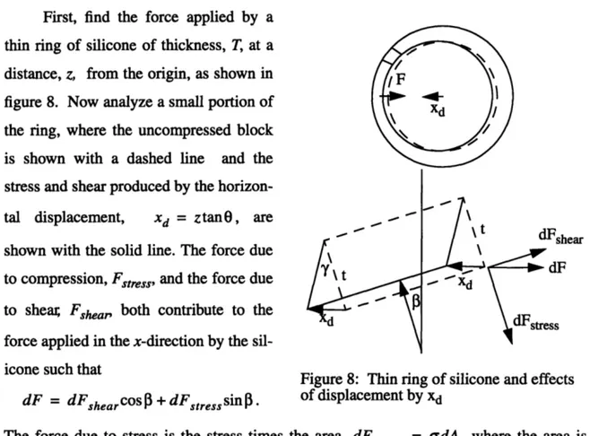
First, find the force applied by a thin ring of silicone of thickness, T, at a distance, z, from the origin, as shown in figure 8. Now analyze a small portion of the ring, where the uncompressed block is shown with a dashed line and the stress and shear produced by the horizon-tal displacement, xd = ztan0, are
shown with the solid line. The force due to compression, Fstress, and the force due to shear Fshea, both contribute to the force applied in the x-direction by the sil-icone such that
dF = dFshearcos +dFstresssin .
Ll dFshea
r
7 dF
d Fstress
Figure 8: Thin ring of silicone and effects of displacement by xd
The force due to stress is the stress times the area, dFstress = adA, where the area is A = Trd3. The stress is related to the strain as a = EE, and the strain is the ratio of
dis-xd sin
p
placement and the original length, e - d This gives us a stress force of
t
ErTxdsinPdP
stress
t
The force due to shear is the shear times the area,
Fshear = tA, where the shear is T = Gy. To calculate y,
we use two sides of the triangle, xd and t, and the angle between these two sides, 90 - 3, as shown in figure 9. The third side is
s t2+ X2- 2txdsin =
Xd
using the law of cosines. Using the law of sines, Sxdcos _ Xdcos y = asin -= asin S t2 + - 2txdsinP and xd cos
Fshear = asin (GrTdo) .
t2 - 2txdsin3
This gives us a total force in the x-direction applied by a segment of the silicone as dF = dFstresssin + dFshear Cos
ErTxdsin 2
P
doxdCOSP
= + asin t2+X22txd sinI(GrTcos d).
t
2t
+
x-2txdsi
The force applied by the whole ring of silicone is the sum of the forces applied by each segment, where the forces in the y-direction cancel because each has an opposing force in another part of the ring. The force applied in the x-direction is then the integral
F= dF = + asrTxsin GrTcosdp)
f ft /2 + - 2txdsin p
which is, needless to say, a rather daunting integral. If we drop the shear term, we can find the force due to the stress alone, which is an underestimate for the force applied by the ring and therefore an overestimate of the angle of deflection for a given moment, thereby
giving us a safety margin.
Taking into account the symmetry in the four quadrants and substituting for xd, the force due to the stress alone on a ring of height T, at distance z from the origin, is
F ErTxdsin2 _tErTztanOxd
The moment that the silicone applies to the inner cylinder for an angular displace-ment of 0 is the sum of the modisplace-ments applied by slices of elastomer where T = dz. We
know that
dMcy = Fzdz
and integrating gives us
L Lrt
Mcyl d cyl :FZdZ =2 LLErz2tanO" 7tErL3 tan
M = dM = Fzdz = dz = 12t
2 2
This is the moment applied by the thin layer of silicone between the cylinders.
Next, calculate the moment applied by the
2R top layer of silicone as shown in figure 10. The .
top layer has radius R, but the silicone which is attached to the wall of the outer cylinder will also serve to pull or push on the inner cylinder to return to the silicone's original shape, so we use R as the radius of the disk instead of r. The force applied by a small area of silicone is
EZd
dF = odA = EedA = EdA
h Figure 10: Top layer of silicone
where zd = xtanO is the change in height of the elastomer. The moment is then
Mtp= f dF= fAreaE andA.
Using polar coordinates, and substituting for x = r cos
1
givesMp= 4r Er2COs2 tan rdrd = ER4tan
t o h 4h
The sum of the two moments is then
M = M ErL+ 3tan0 Mt 0+ER4tan0 7rL3 EiR4
top 12t 4h ta 12(R - r) 4h
Structural yielding
diame-ter of the tubing, and the madiame-terial it's made out of. Finding the yield strength of the tubing is straightforward if we assume no torsional loads.
For a structure subject to pure bending, the highest stress is at the point farthest from the neutral surface (the surface which experiences no force). In a cylinder, this surface passes through the axis, so the highest stress is experienced at the outer radius. The stress is related to the moment as
-Mby
Izz
where Mb is the bending moment, y is the distance from the neutral axis, and Iz is the moment of inertia along the z-axis [1, pg 256]. The moment of inertia for a cylinder is
Izz = J (r4 - r4 )
where ro is the outer radius and ri is the inner radius. The maximum stress is therefore in
the z direction and is
S -Mbr o
(;
(r4
- ,'
Since the cross-sectional area of the tubing is constant, the force is uniformly dis-tributed and the stress due to axial loading is uniformly disdis-tributed. The stress throughout the cylinder is therefore
F F
in the z-direction.
Since the compressive forces on the leg are considerably higher than the tensile forces, the maximum stress occurs when the material is in maximum compression. The maximum stress is therefore
F Mbro
Mass
The mass is simply the sum of the masses of the tubes, the silicone, and the sensor. For simplicity, assume that the silicone fills the top of the tubes. Assuming the same thickness for both tubes, an overestimate for the mass of the tubes and their caps is
mtubes P= tube(2W2P + 2xLra + 27(L + h)Ra).
The mass of the silicone is approximately
msilicone = Psilicone(21cR tL + R2h) .
The total mass for the axial force sensor is
m = Ptube(2W2P + 21cLra + 21r(L + h)Ra) +
Psilicone(21RtL + 2tR2h) + msensor
where msensor is the mass of the pressure sensor (this can be 0 for sensors which are lighter than the silicone they displaced). It is useful to note that the mass of the silicone increases as the square of the radius whereas the mass of the tubing increases roughly linearly with the wall thickness, the height, and the radius.
Discussion of analysis
Recall that we want the leg to rotate less than 0.72 degrees under loading over 60N-m. The analysis shows that one term in the bending moment increases as the cube of the length of the thin wall of elastomer, while the other term increases as the fourth power of the radius. It also shows that reducing the thickness of the silicone both in the side walls and in the top disk increases the resistance to the bending moment, although it turns out that the side-wall term is dominant. This makes sense intuitively since a thicker block of rubber is easier to compress than a thin one. The drawback to a smaller silicone wall size is that at a certain point, it is difficult to push a high viscosity liquid through a small hole.
As for strength, increasing the radius of the walls decreases the maximum stress by the square of the radius. The mass, on the other hand, increases linearly with the length, L, but as the square of the radius.
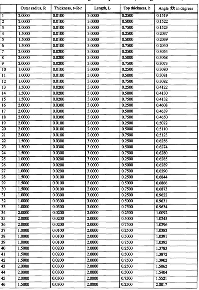
Table 1 gives theoretical values for the angle of deflection given different lengths, radii, etc., with M=80N-m, F=1120N, and E=2.6MPa and G=875kPa,
the values for 60 Shore A durometer [8, pg 33-27]. r- -i
I I
From this table we can see that for the relative sizes for I our sensor, the length has the most effect, followed by
the thickness in the silicone side-wall, and then the I I
radius. The thickness of the upper slab affects the
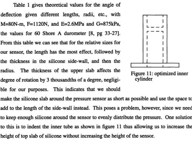
Figure 11: optimized inner degree of rotation by 3 thousandths of a degree, negligi- cylinder
ble for our purposes. This indicates that we should
make the silicone slab around the pressure sensor as short as possible and use the space to add to the length of the side-wall instead. This poses a problem, however, since we need to keep enough silicone around the sensor to evenly distribute the pressure. One solution to this is to indent the inner tube as shown in figure 11 thus allowing us to increase the height of top slab of silicone without increasing the height of the sensor.
Another observation is that a radius of 2" versus 1.5" buys us very little in resistance to rotation, but increases the strength and the mass. If we use a material such as aluminum or carbon fiber, whose yield strengths can be over 80MPa [1, pg 108], the wall thickness needed to withstand a moment of 120N-m and a force of 1112N (250 pounds) for a radius of 2 inches is less than 0.005 inches. At that point buckling is a larger concern than the bending and axial forces. We can conclude, then, that increasing the radius is not neces-sary and increases our mass significantly.
With these guidelines in mind, we chose a design which has a silicone outer radius of R=1.425" and the wall thickness of the cylinders as appropriate for the material being used and the strength needed, although a thickness of 0.075 allows the standard sized leg post to fit inside of the inner cylinder. We experimented with different heights ranging from 1 to 3 inches and chose our thickness to be as low as possible at, t=0.025 inches, while still being able to make the sensors with a viscous silicone. The distance between the tops of the cylinders, h, is 0.5 inches. See Appendix F for CAD drawings.
Table 1: Dimensions and the angle of displacement (all lengths in inches)
Outer radius, R Thickness, t=R-r Length, L Top thickness, h Angle (0) in degrees
2 2.0000 0.0100 3.0000 0.2500 0.1519 2 2.0000 0.0100 3.0000 0.5000 0.1522 3 2.0000 0.0100 3.0000 0.7500 0.1523 4 1.5000 0.0100 3.0000 0.2500 0.2037 5 1.5000 0.0100 3.0000 0.5000 0.2039 6 1.5000 0.0100 3.0000 0.7500 0.2040 7 2.0000 0.0200 3.0000 0.2500 0.3054 8 2.0000 0.0200 3.0000 0.5000 0.3068 9 2.0000 0.0200 3.0000 0.7500 0.3073 10 1.0000 0.0100 3.0000 0.2500 0.3080 11 1.0000 0.0100 3.0000 0.5000 0.3081 12 1.0000 0.0100 3.0000 0.7500 0.3082 13 1.5000 0.0200 3.0000 0.2500 0.4122 14 1.5000 0.0200 3.0000 0.5000 0.4130 15 1.5000 0.0200 3.0000 0.7500 0.4132 16 2.0000 0.0300 3.0000 0.2500 0.4608 17 2.0000 0.0300 3.0000 0.5000 0.4639 18 2.0000 0.0300 3.0000 0.7500 0.4650 19 2.0000 0.0100 2.0000 0.2500 0.5072 20 2.0000 0.0100 2.0000 0.5000 0.5110 21 2.0000 0.0100 2.0000 0.7500 0.5123 22 1.5000 0.0300 3.0000 0.2500 0.6256 23 1.5000 0.0300 3.0000 0.5000 0.6274 24 1.5000 0.0300 3.0000 0.7500 0.6280 25 1.0000 0.0200 3.0000 0.2500 0.6285 26 1.0000 0.0200 3.0000 0.5000 0.6289 27 1.0000 0.0200 3.0000 0.7500 0.6290 28 1.5000 0.0100 2.0000 0.2500 0.6844 29 1.5000 0.0100 2.0000 0.5000 0.6866 30 1.5000 0.0100 2.0000 0.7500 0.6873 31 1.0000 0.0300 3.0000 0.2500 0.9622 32 1.0000 0.0300 3.0000 0.5000 0.9631 33 1.0000 0.0300 3.0000 0.7500 0.9634 34 2.0000 0.0200 2.0000 0.2500 1.0092 35 2.0000 0.0200 2.0000 0.5000 1.0245 36 2.0000 0.0200 2.0000 0.7500 1.0296 37 1.0000 0.0100 2.0000 0.2500 1.0382 38 1.0000 0.0100 2.0000 0.5000 1.0391 39 1.0000 0.0100 2.0000 0.7500 1.0395 40 1.5000 0.0200 2.0000 0.2500 1.3783 41 1.5000 0.0200 2.0000 0.5000 1.3872 42 1.5000 0.0200 2.0000 0.7500 1.3902 43 2.0000 0.0300 2.0000 0.2500 1.5062 44 2.0000 0.0300 2.0000 0.5000 1.5404 45 2.0000 0.0300 2.0000 0.7500 1.5521 46 1.5000 0.0300 2.0000 0.2500 2.0817
Chapter
5:
Prototype Design and Testing
The testing for the prototype was done in two stages. In the first stage, we per-formed preliminary tests to confirm that the design would work, specifically that the pres-sure sensors can operate when covered with elastomer and that the output voltage changes when the sensors are compressed. The heights of the thin elastomer wall were varied to test the actual angle of rotation under bending. In the second stage, the pressure sensors were tested again with different heights and also with a different, more robust, design. The accuracy of these sensors was tested using an Instron machine.
First stage of testing
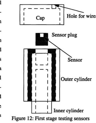
For the first round of tests, the axial force sensors were made so that the
pres-Cap I Hole for wires
sure sensors could be swapped between I Cap I
cylinders with different lengths of
elas-Sensor plug
tomer. Three cylinders were made with thin wall elastomer lengths of 2, 2.5, and
3 inches, and three sets of sensor plugs I I Sensor
were made, one with a Motorola r
-MPX5999D, one with an ACSI Model I I Outer cylinder 7000 500 PSI, and one with a
combina-tion of the Interlink 0.2" sensor and I I Motorola MPX5999D. The axial force In
.... Inner cylinder
sensors fit together in three pieces as
Figure 12: First stage testing sensors
shown in figure 12: the hull with the two
cylinders and elastomer, the plug with embedded sensor, and a cap which fits on top of the outer cylinder and keeps the sensor in place. The sensor plug fit into the top of the inner cylinder which was hollowed out to minimize the length of the entire sensor while maxi-mizing the length of the elastomer wall. This design does not allow the sensors to be put in tension, but it does allows them to be preloaded by adding spacers under the sensor plug. The wires for the sensor come out the top through the cap.
To make the sensors, the inside of the outer cylinder and the outside of the inner cylin-der were primed with GE Primer SS4155.
Teflon spray was used on surfaces that were not I I
supposed to have silicone. To keep the wall I top of sensor
L J thickness even, the inner and outer cylinders r -I
were placed in a stand when curing as shown in Y
stand
figure 13. Three different methods were used to get the elastomer into between the cylinders.
Figure 13: Mold-making stand For the first cylinders, the viscous silicone liquid
was spread on the inside of the outer cylinder, it was placed into the stand, and then the inner cylinder pressed into place. Although messy, it turned out to be the best method because the silicone filled all the crevices, and the extra silicone is easily peeled off of sur-faces that have not been primed. The second cylinder was made by spreading the silicone on the inner cylinder, placing the outer cylinder into the stand, and forcing the inner cylin-der into place. This resulted in a lack of silicone near bottom of the cylincylin-ders (top of the sensor) which had to be filled in later by filling up the stand with silicone and pressing the sensor back in, leaving air pockets in the sensor. The third sensor was made by placing the outer cylinder on the stand, leaving some silicone in the bottom of the outer cylinder, spreading the silicone on the outside of the inner cylinder and then pressing the inner cyl-inder into place. This method also has the potential of leaving air pockets.
The sensor plugs were made by filling a cylindrical mold with silicone, putting the sensor into place, and then screwing on a cover plate (with a hole left for the sensor's wires) to make the top flat. This was successful for the ACSI sensor, but care had to be taken with the Motorola sensor to not get silicone in the back port. Double stick tape was used to hold the sensor on the top plate and lower it onto the silicone, but the tape didn't hold, the sensor was off center, and the thickness of the tape made the sensor surface lower than the plug surface. Normally, the silicone is supposed to be exposed to a vacuum of 26mmHg, but since this wasn't done air bubbles rose to the top of sensor plugs and stayed there since there was no means of escape.
First stage tests
Two tests were performed with the first stage sensors. For the first test, the deflec-tion for a given moment was measured by placing weights at the end of an aluminum shaft attached to the inner cylinder. The outer cylinder was held in a vice, and the deflection of a point 21" from the lower edge of the outer cylinder was measured. Weights of 2.5, 5, and
10 pounds were hung at the end of the 0.5 inch aluminum shaft, 30.25 inches from the
bot-tom of the outer cylinder. The deflection of the shaft alone was subtracted from the mea-sured deflections giving the deflection due to the sensor alone. Sensors with thin wall lengths of 2, 2.5, and 3 inches were tested. While these tests were being performed, the voltage output of the Motorola sensors was monitored to see how the moment affects the sensor output. Repeated measurements were taken by loading and unloading with the weight.
The purpose of the second test was to observe how the voltage under an applied moment was affected by the Motorola pressure sensors being off-center. We measured the change in the voltage output for a given moment at different orientations of the cylinder. As before, the 10 pound weight was applied to the Motorola sensor in the 3 inch cylinder which was rotated along its axis to orientations of 0, 90, 180, and 270 degrees. Repeated measurements were taken by loading and unloading with the weight.
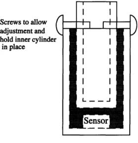
Second stage of testing
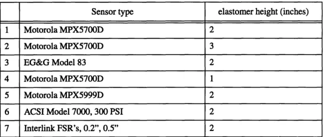
The second set of sensors were made from two capped aluminum cylinders as shown in figure 14. The inner cylinder was flat on top to simplify the machining, and had tapped holes in the side to adjust its place-ment before the silicone cures. Screws extending from the inner cylinder rest on the edge of the outer cylinder to keep the cylin-ders at the right distance, and to center the inner cylinder. Seven axial force sensors were made, as shown in table 2, with
Motor-Screws to allow adjustment and hold inner cylinder
in place
I I
II
I I
Sensor
Figure 14: Stage two test
Table 2: Second stage sensors
Sensor type elastomer height (inches)
1 Motorola MPX5700D 2
2 Motorola MPX5700D 3
3 EG&G Model 83 2
4 Motorola MPX5700D 1
5 Motorola MPX5999D 2
6 ACSI Model 7000, 300 PSI 2
7 Interlink FSR's, 0.2", 0.5" 2
ola MPX5700D sensors at elastomer wall heights of 1, 2, and 3 inches, and 2 inch wall heights for the Motorola MPX5999D, EG&G Model 83, and ASCI Model 7000, 300 PSI, pressure sensors and a sensor with two Interlink FSR's of diameters 0.2 and 0.5 inches. The wires for all sensors except the EG&G Model 83 came out of the side of the outer cyl-inder. The EG&G model had a half inch cylinder on top so that the force was applied to the cylinder, not the electronics.
The axial force sensors were made by gluing the pressure sensors to the top of the outer cylinder, filling the outer cylinder with silicone and then pressing the inner cylinder into place. The Motorola pressure sensors were attached with a ring of 5 minute epoxy around the bottom edge, held in place while it dried (with the metal cap loosened, but taped on) and centered using a pointed rod through the air hole in the top of the outer cyl-inder. The EG&G sensor was screwed into the top but not glued. The ACSI sensor was epoxied in place. Interlink sensors were allowed to hang freely in the outer cylinder, but were held in the correct orientation and distance by filling the hole for the wires with epoxy. All the wire holes for the other sensors were filled with epoxy as well.
All of the sensors were filled with silicone in the same way. First, the appropriate
surfaces were primed, and the screws were adjusted so that the gap between the cylinders was even. After mixing the silicone, it was poured into the outer cylinder, and then placed in a makeshift vacuum chamber (using a vacuum cleaner). After 15 minutes, the inner
cylinders were forced down into the outer cylinders, causing the silicone to fill the thin wall and then pour over the sides. When enough of the silicone had been pressed out, the inner cylinder was fixed into place with the screws. While this method worked, it required a lot of force to push the inner cylinders down, and might be the cause of variation in the preloading of the sensors.
Second Stage Tests
Each of the seven sensors was tested using an Instron machine to determine how the voltage output varied with the force applied. The Instron machine was used with com-pression heads to apply a sine wave of frequency 0.01Hz and amplitude 448N (1001bs) centered around 448N giving an input force which varies from 0 to 996N (200 lbs). The data was sampled at 10Hz, and then averaged over one second intervals to produce one value per second. The data was averaged to counteract the noise added by the connection to the data acquisition card.
Table 3: Stage 1: Moment versus Angle of Rotation test Displacement of sensor only (inches) and
Actual and theoretical angles of deflection (degrees)
8.8N-m (2.51b weight) 17.5N-m (51b weight) 35N-m (101b weight)
Sensor Disp. Oactua Otheory Disp. Oactual etheory Disp. Oactual 'theory
2" 0.156 0.43 0.215 0.187 0.510 0.43 0.156 0.426 0.86 2.5" 0.0 0.0 0.184 0.0 0.0 0.26 0.094 0.256 0.42 3" 0.031 0.085 0.058 0.031 0.085 0.12 0.094 0.256 0.23
Results
Stage 1 ResultsTable 3 shows the results of the moment versus angle of rotation test. Deflection values are given for the point which was 21" from the end minus the deflection of the rod of aluminum alone. These numbers are then turned into angles of rotation (Oactual). The theoretical values for the angle of rotation are included, and were calculated using the rela-tions developed earlier.
theoret-ical values although some are higher and some are lower. The displacement values for the 2.5" sensor were unexpected, but the wall thickness of the sensor is not actually uniform, and most likely the sensor was tested at an orientation where the inner cylinder was already at an angle, and no more deflection was possible. As we would expect, the 2 inch cylinder had a larger angle of deflection than the 3 inch cylinder, with the largest angle of deflection at 0.426 degrees for 35N-m on the 2 inch cylinder. Since the design requires at most a 0.72 degree of rotation at 80N, and since the rubber is not linear at high stresses, we may be able to get small enough rotations even at 80N-m. Because of this, we decided to experiment with thin wall heights around 2 inch for stage 2.
Table 4 shows the results of the moment versus output voltage test done with the 10 pound weight. This data is in line with our expectations. Since the 2.5 inch did not deflect much in the test, the voltage did not change much. For the 2 and 3 inch sensors, the volt-age difference was higher for higher moments, and the 2inch sensor, which experienced a higher angle of rotation, also experienced a higher voltage change. The unloaded output is given in the results since the preloading was different for different lengths of tubing.
Table 4: Stage 1: Moment versus Motorola MPX5999D output
Sensor 2.51b (mV) 51b (mV) 101b (mV) Unloaded output (V)
3" 2 4 9 0.46
2.5" -1 -1 1 0.57
2" 17 24 27 0.54 to 0.59
In order to understand the values from the previous experiment, we decided to see if the orientation of the axial force sensor under bending made a difference in the output of the pressure sensor. The results reported in table 5 show that this was the case. Close examination of the sensors while placed in the 2 and 3 inch cylinders, shows that the Motorola sensor is not centered (the center is assumed to be at the port based on the draw-ings in the Motorola data sheets). Regardless of where the sensor is, though, we expect that loading it at 0 degrees should give an equal and opposite value from loading it at 180 degrees if the pressure is not evenly distributed, and should give no change in value if the pressure is evenly distributed since there is no change in volume. Things are not quite this
simple, though, since the fluorosilicone in the Motorola sensor is sticky and will change shape when the silicone moves. The values were opposites for everything except the 2 inch sensor for 0 and 180 degrees which were both the same sign and equally large. This is puzzling, but we can conclude that it is important to center the Motorola sensor so that the bending moment affects it as little as possible, and that a softer silicone gel in the cap may be necessary.
Table 5: Moment vs. Orientation of sensor (MPX5999D)
Orientation
Sensor 00 (mV) 900 (mV) 1800 (mV) 2700 (mV)
3" -11 -15.8 0.3 19
2" 20.75 -3.2 18 -18
Stage 2 Results
The results of the Instron tests of force versus sensor output are shown in figures 15 through 19. (Results for the ACSI Model 7000, 300psi sensor were omitted because we were unable to get it sufficiently amplified during the test. Stage 1 experiments showed that it did work while embedded in silicone though.). Figures 15 through 18 show the Motorola MPX5700D and MPX5999D tests with thin wall lengths of 1, 2, and 3 inches for the Motorola MPX5700D and 2 inches for the MPX5999D. The force versus displace-ment curves are fairly linear except for an unexpected abnormality in sensor 1 (figure 17) and show a difference of 0.4V across 200 pounds, a sensitivity of 2mV/lb. Sensor 1 was most likely preloaded in tension. If the resistance is the same for values in tension or com-pression, then the dip is caused by going from tension to compression in the sensor.
The Motorola sensors show a distinct hysteresis. Figure 20 shows the output for one cycle of the force, and figures 15 throughl9 indicate output values during increasing force with 'o's and decreasing force with 'x's. As we can see, the falling edge tends to the upper side of the curve, and the rising edge to the lower.
When an Interlink sensor has no force applied, there is actually no resistance across it, but when contact is first made, the resistance drops to 2MQi Tests on Interlink sensors
Motorola MPX59999, 2"
(sample 5)
I I I I I I0
0 Forward path
x
x Backward path
-50'
I I I I I I I I0.4
0.5
0.6
0.7
0.8
0.9
1
1.1
1.2
1.3
Sensor output in
volts
Figure 15: Motorola MPX5999D, 2" wall height, sensor output vs. force diagram
250
200
k
150
F
C 0 08100
0 L U.50 F
Motorola MPX5700D
1'
(sample 4)
I I I I0
0
Forward path
x
x Backward path
XX X )K x X xx S xxXX X
4
Xx
x
X XXxx
%
0 x0 XSensor output in
volts
Figure 16: Motorola MPX5700D, 1" wall height, sensor output vs. force diagram
250
200
150 F
100
50
-50
Motorola MPX5700D, 2' (sample
1)
250
'0 r0.
100
o 0 0L0.15
0.2
0.25
0.3
0.35
0.4
0.45
0.5
0.55
Sensor output in
volts
Motorola MPX5700D, 3"
(sample 2)
I I I I I I I0
0 Forward path
x
x Backward path
x x
X
0.5
0.6
0.7
0.8
0.9
1
1.1
1.2
1.3
Sensor output in
volts
Figure 18: Motorola MPX5700D, 3" wall height, sensor output vs. force diagram
250
200
1
150
F
'0 0 . 100 U, L50
-50
0.4
EG&G Model 83,
2"
(sample
3)
I I I I Io
0
Forward path
x
x Backward path
x
x 0 x0
x
oX
x I I I I I I I-3
-2
-1
Sensor output in
volts
Figure 19: EG&G Model 83, 2" wall height, sensor output vs. force diagram
250
200
F
150 F
C 0 0o 100 0L-50
F
-501
-4
Q
8xx
250
Motorola MPX59999, 2", single path
mi xx-" X
,
10000 x 0 50- xx ) Ox !D 0-0 -50 1 1.1 1.2 1.3 1.4 1.5 1.6 1.7Sensor output in volts
Figure 20: Single cycle of the Motorola MPX5999D sensor
in stage 1 and stage 2 axial force sensors showed that the Interlink sensors are not very sensitive when embedded in silicone. Sometimes the sensor would go off after significant (20 pounds or more) weight was put on the axial force sensor, and sometimes they wouldn't go off at all. In the stage 2 sensor, after a period of testing, one sensor was per-manently off, and the other was perper-manently on.
The EG&G Model 83 sensor showed promising results. The force versus voltage curve, as shown in figure 19 shows no significant hysteresis, a thinner band of values, and high accuracy at low forces. The clustering of voltages at -3 and 3V is most likely due to amplification circuit since the EG&G sensor has an internal wheatstone bridge and the
Force vs. Displacement for 1", 2" and 3" sensors + x 00 + + XX 0 -c 100 _+44w 0 00 ,t 0 O0 O 0 ,+ 0 + ++ + S50 x 0 o -50 0 0.05 0.1 0.15 0.2 0.25 Displacement in mm
Figure 21: Force versus displacement curves for 1", 2" and 3" stage two sensors output can be amplified as needed. The EG&G sensor is rated up to 300psi, so its full range is much greater than we would have reached with 200 pounds of force applied across a 1.5 inch diameter circle.
The Instron machine is able to measure the displacement of a sample, so we include here force versus displacement curves for the stage 2 sensors of heights 1, 2, and 3 inches (axial loading only) in figure 21. The results followed our expectations, with the 3 inch sensor displacing least. The strain, E, is equal to the displacement, d, over the length, L, of the thin silicone wall, and
F= A = EeA = E A
where F is the force, E is the Young's modulus, A is the area, and a is the strain. This tells us that for a constant force, the displacement is proportional to the length.
![Figure 1: Walking cycle (from Human Walking, Inman et. al [6], page 26)ARihcorCB I](https://thumb-eu.123doks.com/thumbv2/123doknet/14139190.470133/8.918.137.722.128.1007/figure-walking-cycle-human-walking-inman-page-arihcorcb.webp)
![Figure 2: Axial force sensor designed by Cullen (taken from [3], pg 51)](https://thumb-eu.123doks.com/thumbv2/123doknet/14139190.470133/10.918.148.708.151.1012/figure-axial-force-sensor-designed-cullen-taken-from.webp)
![Figure 3: Axial force sensor modified by Goldfarb (taken from [4], pg 34)](https://thumb-eu.123doks.com/thumbv2/123doknet/14139190.470133/11.918.180.788.149.965/figure-axial-force-sensor-modified-goldfarb-taken-from.webp)