Automated CAD Assembly and its Application in DOME
by
Prabhat K. Sinha
Bachelor of Technology in Mechanical Engineering Indian Institute of Technology, Kanpur, India (2000)
Submitted to the Department of Mechanical Engineering in Partial Fulfillment of the Requirements for the degree of
Master of Science in Mechanical Engineering
at the
MASSACHUSETTS INSTITUTE OF TECHNOLOGY
June 2002
C2002 Massachusetts Institute of Technology All rights reserved
Signature of Author...
Department of Mechanical Engineering
AIM 8, 2002
Certified by... ... . ...
Professor David R. Wallace Esther and Harold Edgerton Professor of Mechanical Engineering Thesis Supervisor
Accepted by..._..
Professor Ain A. Sonin Chairman, Departmental Committee on Graduate Students
MASSACHUSETTS [NSTITUTrE OF TECHNOLOGY
OCT 2 5 2002
MIT
Libraries
Document Services Room 14-0551 77 Massachusetts Avenue Cambridge, MA 02139 Ph: 617.253.2800 Email: [email protected] http://libraries.mit.edu/docsDISCLAIMER OF QUALITY
Due to the condition of the original material, there are unavoidable flaws in this reproduction. We have made every effort possible to provide you with the best copy available. If you are dissatisfied with this product and find it unusable, please contact Document Services as soon as possible.
Thank you.
Due to the quality of the original material there is some bleed through.
Automated CAD Assembly and its Application in DOME
by
Prabhat K. Sinha
Submitted to the Department of Mechanical Engineering on May 8, 2002 in partial fulfillment of the
requirements for the degree of
Master of Science in Mechanical Engineering
Abstract
Solid modeler/CAD (Computer Aided Design) packages do not fully automate the assembly of parts. This is primarily because solid modelers cannot interpret the design intent of an assembly and thus think like an assembly engineer. One is required to specify low-level mating constraints between parts to assemble them together, which can be both tedious and time consuming. This affects the product development cycle.
This work is intended to provide the basis for an efficient tool to assembly engineers that will help them in faster assembly of parts, analyze the assembly system efficiently and produce results quickly. While such a methodology could never replace/substitute for CAD assembly engineers, it may help to reduce tedious procedural assembly tasks. The thesis discusses issues associated with trying to increase the level of automation in a CAD assembly processes.
Considerations that might be helpful for developing an Automatic Assembly Algorithm (AAA) are detailed. These include dimensions, topology, geometry, feature, functionality, orthographic views, assembly constraints etc.
This work is a starting step towards automating the assembly of CAD parts. The long- range vision is to more fully automate the assembly process and do the full analysis of the assembly in the virtual environment.
The automated assembly concept may also be useful in DOME (Distributed Object-based Modeling Environment) for building heterogeneous CAD assemblies, where parts from different distributed CAD systems can be assembled together to create a parametrically editable assembly.
Thesis Supervisor: David Wallace
Acknowledgments
I wish to express my sincere gratitude to Professor David Wallace, my thesis advisor, for his constant support, encouragement and insightful guidance during my stay at MIT. He offered just right amounts of structure and flexibility - research support with allowance to go where the research takes me. I have gained a lot, both academically and in personal life, while interacting with him. He is a wonderful teacher and a good friend. I thoroughly enjoyed working with him. I am happy to have had the opportunity to work with him.
Thanks to all the MIT CADlab students, Aubrey Williams, Kristie Yu, Ines Sousa, Qing Cao, Twiggy Chan, Sane Wu, Rainer, Vishal and Charles for bringing up a family like atmosphere in the lab that had a great refreshing effect during day to day research work. The lab has been home-away-from-home during my life at MIT.
Thanks to Leslie Regan and Maureen Lynch for taking care of all the administrative matters.
My very special thanks to Elaine Yang for all the help in the lab. I thoroughly enjoyed interacting with her. Despite her own busy schedule, she has always been ready to help me out in various aspects of CATIA@ programming and other computer related problems. She always encouraged and motivated me. I really admire her for her perseverance and penchant for perfection and working with her has been a memorable experience.
Special thanks to Darcy for her help in searching papers for my research. She always whole-heartedly welcomed my queries in library related issues.
My very last, but the most precious thanks to my family. Mom and Dad, I really missed you here. Ajit Bhaiya, I missed you too. Chatting R-brothers had also been refreshing. Thanks for all the belief in me, and providing me a lifetime emotional support and motivation without even knowing it.
Table of Contents
A B ST R A C T ... 3 ACKNOWLEDGEMENTS ... 5 TABLE OF CONTENTS...6 L IST O F FIG U R ES ... 9 LIST OF TABLES ... 9LIST OF ACRONYMS AND SYMBOLS...10
1. INTRODUCTION...11
1.1 V ision ... 12
1.2 Mission: Goal and Deliverables of this Thesis...12
1.3 Automated Assembly and its Role in Product Development Process...12
1.4 Organization of Thesis...15
2. BACKGROUND...17
2.1 Evolution of CAD Package...17
2.2 Extensive Mouse Click/ Key Pressing Operation and RSI...18
2.3 Repetitive Tasks and its Effect on Creativity and Productivity...19
2.4 Experience of a Ford Engineer...20
2.5 Work in Assembly Planning and Automated Assembly...20
3. CAD ASSEMBLY: CURRENT STATUS...22
3.1 Generic Assembly Process In CAD Packages...22
3.2 Illustrative Assembly Example in SolidWorks®...23
4. FACTORS FOR AUTOMATING CAD ASSEMBLY...28
4.1 Concept Overview...28
4.2 Factors for Automating Assembly...28
4.2.1 Dimension Driven CAD Assembly...28
4.2.2 Topology Driven CAD Assembly...31
4.2.3 Geometry Driven CAD Assembly...35
4.2.4 Functionality Driven CAD Assembly...36
4.2.5 Feature Driven CAD Assembly...36
4.2.6 Orthographic View Driven CAD Assembly...38
4.2.7 Library Driven CAD Assembly...41
4.2.8 Constraints Driven CAD Assembly...42
4.2.9 Other Factors Helpful for Automating CAD Assembly...44
4.3 PROPOSED METHODOLOGY...45
5. EXTRACTING PART INFORMATION FROM CATIA SOLID MODELS...47
5.1 Introduction to [email protected]
5.2 CATIA@ Plugin...48
5.3 Example and Discussion of Obtained information...52
6. AUTOMATED ASSEMBLY AND ITS APPLICATION TO DOME...55
6.1 Introduction to DOME and Overview of its Architecture...55
6.2 Assembly Work in DOME...56
6.3 ST E P ... 60 6.4 IG E S ... 6 1
6.5 Proposed Methodology...63
7. C O N C LU SIO N S ... 66
7.1 Sum m ary ... 66
7.2 Advantages of Automated CAD Assembly...67
7.3 Challenges and Limitations...68
7.4 Future W ork...70
APPENDIX A: Evolution of CAD Database...71
APPENDIX B: Program for Extracting Part Information in [email protected]
APPENDIX C: STEP (AP214) of the Peg ... 77
APPENDIX D: IGES of the Peg ... 83
List of Figures
Figure 1: Flow chart: Product Development Process...13
Figure 2: Assembly in Product Development Process... 13
Figure 3: A Peg (Part 1)... 23
Figure 4: A Cone (Part 2)...23
Figure 5: Base Part (Part 3)...23
Figure 6: Parts in assembly...24
Figure 7: Concentric assembly mating...25
Figure 8: Coincident assembly mating...25
Figure 9: Other assembly matings...26
Figure 10: Assembly automation of angle bracket subassembly using dimension information...30
Figure 11: Difference between geomery and topology of an object...32
Figure 12: The geometric (a) and topological (b) elements that define a simple cube...33
Figure 13: Topologically same and geometrically different Solid Models...34
Figure 14: Using topological information for automating CAD assembly...35
Figure 15: Feature based approach for automating peg, cone and base part CAD assembly...38
Figure 16: Orthographic views generated in [email protected]
Figure 17: The lower figure represents skeletal representations of the figure above...41
Figure 18: Set of assembly rules for standard library parts...42
Figure 19: Basic flow chart of automated assembly in a CAD package...45
Figure 20: Pseudo code for assembling hole-shaft feature...45
Figure 21: Extracting various parameters and properties of the peg (shown top right)...52
Figure 22: Extracting various parameters and properties of the cone (shown top right)...53
Figure 23: Extracting various parameters and properties of the cone (shown top right)...54
Figure 24: Step 1: The two participants publish their CAD models and wrap them in DOME...56
Figure 25: Step 2: The engineer drives the supplier's CAD model parametrically from DOME...57
Figure 26: Step3: The supplier drives the engineer's neutral file service by linking it to his own....58
Figure 27: The engineer incorporates the new part into his assembly...59
Figure 28: The engineer rebuilds his assembly by driving the supplier's model...66
Figure 29: Different ways of defining a cone...69
List of Tables
Table 1: Total number of mouse clicks for the cone-peg assembly...27List of Acronyms and Symbols
AAA Automatic Assembly Algorithm ANSI American National Standards Institute
CAD Computer Aided Design
CADLab Computer Aided Design Laboratory
DFA Design for Assembly
DOF Degrees of Freedom
DOME Distributed Object-based Modeling Environment
H-CAD Heterogeneous CAD
IGES Initial Graphics Exchange Specifications ISO International Organization for Standardization
KC Key Characteristics
LUT Look Up the Table
MIT Massachusetts Institute of Technology
NF Neutral File
NIST National Institute of Standards and Technology OEM Original Equipment Manufacturer
PDM Product Data Management
RADE Rapid Application Development Environment RSI Repetitive Stress Injury
STEP Standard for the Exchange of Product Model Data
2-D Two Dimensional
3-D Three Dimensional
1
Introduction
Accelerating time to market with improved product quality is one of the driving forces encouraging companies to seek high level of automation in the product development process. The corporate world has placed emphasis on reducing cost and increasing the quality of assembled products and thus improved techniques for producing finished assembled products are part of this trend.
In a complex product, assembly is often the dominant cost process in comparison to detail part manufacturing operations. For Example, it has been argued that more than 30% of manufacturing cost or financial value of a civil aircraft is incurred during assembly [1]. With the automation of CAD assembly, the time and resources to analyze the assembly will decrease, which, in turn, should drive down the total assembly cost. In addition, for the case of new products, a thorough and detailed assembly analysis is required before a production system is conceived, designed and built, and successful assembly operations can be achieved.
Computer-aided Design (CAD) activities are integral parts of Product Design and Development. Currently, the process of assembling parts in CAD packages requires the user to execute many repetitive steps. Thus, the process of assembly within a CAD system might be further explored to minimize repetitive, low information adding tasks. CAD systems do not reason about parts in the way assembly engineers think while performing assembly analysis, or as assembly workers think while working in an assembly plant. Thus, engineering must build CAD assemblies in an unnatural language. In addition, it is simply
time consuming to specify low-level assembly mating constraints in cases where parts can assemble in only one possible way.
1.1 Vision
The long- range vision is to more fully automate assembly process of CAD solid models by reducing the number of procedural assembly steps, which add little information, and to provide the full analysis of assemblies in a virtual environment. With the helps of enabling tools, assembly engineers will be able to assemble parts quickly and analyze assembled systems in a rapid development cycle.
1.2 Mission: Goal and Deliverables of the Thesis
The goal of the thesis is to identify various factors that can help in the automation of solid models assemblies in CAD environments and to explore the benefits of such methodology in a DOME platform. DOME is a modeling infrastructure that is intended to create a global community, or marketplace, of individuals offering access to simulation services related to their own specialties, much as the WWW has enabled worldwide access to information ([37], [38] and [39]). There are four major components of the thesis. First, there is a description of current status of assembly in CAD system. Second, various factors that can help in automating the assembly process and the methodology for automation of assembly are discussed. Third, a plugin that extracts various part related information from solid models of part made in CATIA@ is described. Fourth, there is a discussion on the possible application of automated assembly methodology in DOME.
Following section describes a generic product development process and identifies stages (of the product development process) at which automation of CAD assembly can be helpful.
1.3 Automated Assembly and its Role in Product Development Process
A product development process is the sequence of steps or activities, which an enterprise employs to conceive, design and commercialize a product [2]. Product Design includes every technical aspect of the product, from the purchasing of components to manufacturing, assembly, service and obsolescence. Ulrich and Eppinger's flow chart representation for a
generic product development process is shown in Figure 1. The process begins with a mission statement and ends with product launch. There are seven key activities in between.
Mission Identify Establish Generate Select
Statement Ietf
h. Customer Target Product o Product
Needs Specifications Concept Concept(s)
4-I 4-I
-Development
Test Set Prototype and Plan
---
Product Final 10 Downstream
Concept(s) Specifications Development
Figure 1: Flow Chart: Product Development Process
Thinking about the assembly of parts, either directly or indirectly, comes at various stages of the product development process as shown in Figure 2. The proposed Automated Assembly Algorithm (AAA) may help in various steps of the product development process.
Mission
Statement Identify Establish S.-ect
. Customer Target froduct
Needs Specifications oncept concept(s)
4,1
Development Prototype and Plan
Product -- - Downstream
Concept(s) pDevelopment
Depending upon the need, the CAD may be used in the early stages of the product development process, starting from the concept generation stage. The goal of the concept generation stage is to thoroughly explore the space of product concepts that may address the customer needs and solid modeling may not initially be useful in this stage. However, the strength of CAD comes into play when designers wants to understand part interactions in an assembly which otherwise is not possible in 2-D sketching. In addition, CAD models help in the communication of concepts between team members.
Concept generation activities usually result in a set of 10 to 20 concepts. The next stage in the product development process is Concept Selection (step 4, Figure 2). Concept selection is the activity in which product concepts are analyzed and sequentially eliminated to identify the most promising concept(s). Once a solid model is made (and if it has been made in step 3 of Figure 2) it can help the product design team during concept selection.
In step 5, Test Product Concepts, the shortcomings of selected concept(s) are identified and many incremental variations are produced. The configuration of an assembly any of its parts can be modified in a solid modeler and then reassembled automatically with Automatic Assembly Algorithm (AAA).
Up until step 5 of the product development process, a CAD system may or may not be used depending upon the need. But, in the following step, Set Final Specifications, it is important to use CAD systems in most cases. This step requires the careful analysis of the assembly and setting up final part dimensions and tolerances before prototyping. Error or mistakes in this phase can lead to large expenses in the prototyping phase. The need and impact of the automatic assembly process is the most in this phase where parts are designed and changed iteratively and is assembled together to see if all the parts fit together correctly.
In addition to new product development, the automatic assembly of parts is useful when some parts of an existing design are modified and parts of the subassembly should reassemble in the same, similar or different way. Section 2.4 describes experience of a Ford
engineer where he hard-coded automatic assembly code in I-DEAS@ for assembling standard engine parts. As a part of his job he had to reassemble modified standard engine parts which were sent to him from various design specialists (heat and fluid specialist, assembly engineer, part design engineer etc.). Automating assembly using hard-coded part specific procedures made him much more efficient in his day-to-day activities, leaving more time for creative thinking.
1.4 Organization of Thesis
In chapter 2, background materials for the thesis is presented. The evolution of CAD packages is described with an emphasis on the wide range of capabilities of contemporary CAD packages. Next, Repetitive Stress Injury (RSI) due to extensive mouse clicking operations and key pressing is discussed. The effect of repeated tasks on creativity and productivity is also explained. The experience of a Ford Motor Company engineer is described who hard-coded an automatic assembly code for assembling a set of standard engine parts is presented. The chapter concludes with review of past research work in assembly planning and automated assembly.
In chapter 3, current status of generic assembly process in CAD Packages is described. The generic assembly process is illustrated by taking example of three simple solid model designed and assembled in SolidWorks®.
Chapter 4 discusses factors that should be helpful in automating the assembly process. The overall concept of automated assembly is also provided. An overview of proposed methodology and description of the knowledge base that is essential for the implementation of the concept is discussed. A basic flow chart of the process of automated assembly is provided.
In chapter 5, the CATIA® plugin for extracting part information is described and is illustrated by taking examples. Discussion on the nature of parameters obtained with the help of plugin is also presented.
In chapter 6 the concept of DOME is described briefly. An assembly process in the DOME environment is explained as a methodology has been proposed for implementing automated assembly in DOME environment [40]. Factors that affect the extent of assembly automation are also listed.
Chapter 7 summarizes the work presented in the thesis with conclusions and advantages. Limitations and challenges of the proposed automated methodology are discussed. Direction for future studies and work is also provided.
2
Background
2.1 Evolution of CAD Packages
CAD packages have evolved considerably since their advent in the mid 1960s. The design tasks in earlier CAD packages were restricted to describing parts geometrically by creating drawings using orthographic projections. The first 3D CAD system appeared in early 1970s with the capability of simple skeletal wire frame drawings [3]. Thereafter, important milestones on the road of 3D development involved wire frames with hidden line removal, two and a half D', 3D surface modeling and then 3D Solid modeling.
CAD systems presently fall into two general categories: those based on entities and those based on solids or features [4]. The entity based CAD system has basic entities such as line, circle or arc, spline etc, and it can be thought of as a powerful implementation of the drawing board. An example of such system is AutoCAD. On the other hand, in solids or feature based CAD systems, the design process starts with creating a solid model using primitive shapes or features. Examples include solid extrusions, revolved solids, or solid created from general surfaces. There are also solid removal features such as holes, cut and chamfers. In addition, these solid modelers are parametric. This allows the part to be reshaped by changing dimensions. The parametric CAD system automatically reshapes the model or part when the dimensions or parameters are modified. Examples of such systems are Pro/ENGINEER@, I-DEAS@, CATIA® and Unigraphics@.
1 Two and a half D means that Drawing objects, like lines, circles etc. having a "Thickness" value. Thickness in fact means height! All the data is the same size, a zero thickness is stored in the same manner as a height of
With the evolution of part design within a CAD system, CAD databases have also evolved in a parallel. While earlier databases were developed to store 2D drawings, recent databases are capable of storing data corresponding to the solid model, shape extraction and product model. Appendix A provides a schematic representation of CAD Database evolution.
The aforesaid development in part design within a CAD package and the corresponding evolution in the internal representation of a solid model in its database has enabled CAD systems to understand various aspects of a parts, similar to the way we may understand geometry. Hence, it is now a natural choice to delve into the automation of CAD assembly process by investigating the thought process of an assembly engineer and exploring other factors that can help the automation process.
One of the main drawbacks of the assembly process with current CAD packages is that it requires extensive clicking of mouse buttons, dragging mouse while holding one of its buttons and providing various inputs with the help of keys. Next section describes the adverse effect of such repetitive operations.
2.2 Extensive Mouse Click (mousing)/ Key Pressing (keying) Operation and RSI
References [5] and [6] indicate that the majority of Repetitive Stress Injuries (RSI) are related to extensive computer use. Repetitive Stress Injuries (RSI) are injuries involving damage of muscles, tendons and nerves caused by overuse or misuse. Repetitive Stress Injuries develop slowly over time; thus, they are also called Cumulative Trauma Disorders (CTD) or Muscular Skeletal Disorders (MSD). They usually affect hands, wrists, elbows, arms, shoulders, back, or neck. The repetition of small, rapid movements, such as keying or mousing for concentrated period, results in RSI.
In order to assemble parts in the CAD assembly environment, the user has to perform several mouse click operations, and hold and drag the part to the desire place for assembly. Using a CAD environment in itself requires extensive mousing and keying operations, many of which are essential and necessary. Nevertheless, with concepts developed in this thesis,
the automation of assembly processes should eliminate or minimize keying and mouse click operations by increasing the level of automation.
2.3 Repetitive Tasks and Effects on Creativity and Productivity
People will be most creative when they feel motivated by the interest, enjoyment, satisfaction, and challenge of the work itself. Repetition in task leads to lack of interest, enjoyment, and satisfaction [7]. Creativity is an important tool that organizations can use to increase their effectiveness, competitiveness, and long-term survival [8]. A repeated task does not pose new challenges.
The process of specifying low level mating constraints involves several mouse click operations including selecting parts, performing check button and 'OK' operations are such tasks. The repetition of such tasks naturally decreases the interest, enjoyment and satisfaction, which in turn reduces productivity. Within my own and my peers' experience in using CAD for assembly, I am convinced that spending thought on the procedural operations of the assembly detracts mental energy from thinking about the key issues of design and assembly. Hence, the person doing such operations is not at his creative best. The effect of CAD on creativity had been studied since as early as late 1970s. In 1977, Negroponte [9] mentioned that the then CAD systems were marked by a complete disregard for the notion of creativity.
In a CAD article, "Technology, good for the pocket, bad for the soul!" [10], one CAD Engineer says of his experience, "I cannot help but feel that some of the pride, some of the soul is gone from the my drawings and instead of feeling like the artist I once was, I feel like a robot on a production line...". This statement also reveals how the mundane task reduces the creativity and interest in the job.
Langner et al [11] studied effects of computer aided design work on the design process by conducting various field experiments. Their study focused on the influence of 3 different design tasks (standard tasks) and 11 CAD-systems (2D and 3D), taking into account the performance and strain measurements of 43 subjects (15 design engineers, 8 technicians, 17
draftsmen, 3 trainees). They found that deficits and complications in handling the CAD systems increase with the complexity of the system and thus cause an adverse effect on performance and strain of its operators: creativity is reduced by friction and frustration in
system handling, even if the operator is highly trained.
2.4 Experience of a Ford Engineer
The experience of Ford Motor Company engineer, Rob Mecoli ([email protected]), of the power train group, is one of my motivations to explore CAD assembly automation. He wrote automatic assemble code in I-DEAS@ for assembling standard engine parts. He defined the particular mating surface and the nature of constraints in a code that works like LISP to generate an assembly. This limits the work that he needs to do repeatedly when parts are modified parametrically. The example also shows that generic automatic assembly would be helpful in industry. Ideally, it would also be very useful for new product
development, not just parametric variations of mature designs.
2.5 Work in Assembly Planning and Automated Assembly
There is a large body of work in the area of assembly planning and the automated assembly of parts using robotic systems ([12], [13], [14], [15], and [16]). Chakraborty, et al [12] describes representation of an assembly as a hierarchy of assembly structures. Given a description of an assembly to be manufactured, the assembly sequence planner identifies subassemblies and generates high-level plan for the construction of each subassembly, including the final assembly. Mello [13] presents an algorithm for generating all mechanical assembly sequences by transforming the problem of generating assembly sequences into the problem of generating disassembly sequences, in which the disassembly tasks are the inverse of feasible assembly tasks. Weule et al [14] and Gu et al [15] worked on generating the sequence of operations for assembly lines by evaluating CAD-database and extracting the necessary information. Dini et al [16] describes a procedure for the selection of the subassemblies and the assembly sequences of a product based on a mathematical model of the product, obtained through the definition of three matrices: the interference matrix, the contact matrix and the connection matrix.
In contrast, there seems to be little work on automated assembly planning within the CAD systems themselves. The work presented in this thesis develops a framework whose implementation will help in automating (either partially or fully) assembly processes in CAD systems.
The assembly process within solid modelers ideally will have analogies to the actual manufacturing assembly process. If we are to improve the CAD assembly process, it is important to think about the following questions:
How do we physically assemble?
What factors does an Assembly Engineer think about while assembling parts? How a factory worker thinks while assembling parts in assembly line?
It is often required by students (specially in Mechanical Engineering) to draw a solid model of parts and then assemble those part models into assembly. For these, after making the parts, students have to do various click operations (similar to what stated in the next chapter, CAD Assembly: Current Status) to assemble those parts. The simplification of the assembly process with the help of increased automation will give students more time to think on
3
CAD Assembly: Current Status
3.1 Generic Assembly Process in CAD Packages
The need for a new type of assembly process within CAD systems comes from the experience of using several CAD packages (Solid Works@, I-DEAS@, CATIA@, etc.). This section describes the generic process of assembling parts in various CAD Packages.
Parts defined in CAD packages are stored in different files. To create an assembly using parts, a new assembly file is opened and the parts to be assembled are brought into the file. After specifying various mating conditions, like concentric, coincident, perpendicular, tangent etc, the CAD system generates an assembly using the parts. This highly procedural process takes a lot of time as it involves many mouse-click operations, selection of part surfaces, and the clicking of radio buttons in menus to set constraints.
CAD systems force the user to perform various steps that can often be seen as redundant. Part attributes (like dimensions, geometry, functionality, etc.) might be used to perform automatic CAD assembly in many cases, or at least perform some assembly steps to provide a partially complete assembly.
The example presented in the next section illustrates the assembly of parts in SolidWorks®, which is a common, relatively easy-to-use solid modeler (SolidWorks is the registered trademark of SolidWorks corporation). SolidWorks@ has chosen as a sample package and the process of assembly is similar in other CAD packages.
3.2 Illustrative Assembly Example in SolidWorks@
The following example illustrates the assembly steps while assembling in a solid modeler, SolidWorks@, with three simple parts viz., a peg, a cone, and a base part having conical and cylindrical hole features.
Three illustrative parts follow in Figures 3, 4 and 5.
Figure 3: A Peg (Part 1)
Figure 4: A Cone (Part 2)
Parts in Assembly:
Cone
Peg
Base part
Figure 6: Parts in assembly
In order to achieve the configuration above, the following steps are performed. In general, this is the minimum number of steps one needs to do:
1. Gross Motion: Move part 1 to a desired location (in some cases this may not be required).
2. Apply the CONCENTRIC constraint between desired face of part 1 and the base part using the "Assembly Mating" window shown below in Figure 7.
[A-11semb?
Figure 7: Concentric assembly mating
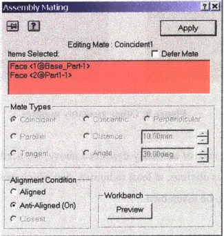
3. Apply COINCIDENT mating condition between appropriate faces of part 1 and the base part, again using the "Assembly Mating" window shown in Figure 8.
Figure 8: Coincident assembly mating
4. Gross Motion: Move Part 2 to a desired location with respect to the Base part (in some cases this may not be required).
5. Apply the CONCENTRIC constraint between desired face of part 2 and the base part (Figure 9).
6. Apply COINCIDENT mating condition between appropriate faces of part 1 and the base part (Figure 9).
d9Apply Ap
Editing Mate : Concenkric4 E ditng Mate Coincddnt4 Items Selected: C e a ito, rA .I t d: .~...
Alignment Conditon Align r G t Condon
Aligned Wo Wodnc
-SAn -Aligned (On)n
Figure 9: Other assembly matings
As seen from the simple case of assembly described above, we need to perform steps in the assembly even though it is obvious, at least to human, that which part has to go where and in what manner they need to be assembled.
The total number of steps for the simple case is 6, and the time taken is around 30 seconds to achieve the Assembled model. The number of steps involved increases as the number
parts increases, and hence, the time taken to assemble them together. This clearly shows the need of work in the area of automatic assembly.
The discussion presented in this thesis is to help provide background for developing an efficient tool for assembly engineers that will help them faster assembly of parts, analyze the assembly system efficiently and produce efficient results in short time.
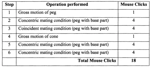
For the case of peg-cone assembly (Figure 6), the total number of mouse clicks required is 18 as shown in Table 1.
Table 1: Total number of mouse clicks for the cone-peg assembly
Step Operation performed Mouse Clicks
1 Gross motion of peg 1
2 Concentric mating condition (peg with base part) 4 3 Coincident mating condition (peg with base part) 4
4 Gross motion of cone 1
5 Concentric mating condition (peg with base part) 4 6 Concentric mating condition (peg with base part) 4 Total Mouse Clicks 18
With the proposed methodology, only gross motions are required, in clicks can be reduced to 2.
4
Factors for Automating CAD Assembly
4.1 Concept Overview
This section details various factors that will provide the basis for the development of efficient tool(s) for automating CAD assembly. The concept described in this chapter involves extracting various geometric, dimensional, and topological information etc. using information that describes a part. In addition, a discussion on how and to what extent other information, like part functionality or specific features, can be helpful in automating CAD assembly is provided. The factors proposed in this chapter utilize tools available in current solid modelers.
4.2 Factors for Automating Assembly
i. Dimension Driven CAD Assembly
Every part and its features have a set of dimensions that define them. This set of dimensions is one of the important attributes of a part that help us decide which part goes where. Parts/features generally have the following three attributes related with dimension.
a. Value of Dimensions (actual numbers).
b. Number of Dimensions used to completely define the part and its features.
c. Nature of Dimension, for example diameter value, angular value, simple length value etc.
Not all the dimensions of a part/feature will be used in an assembly. In fact this will seldom be the case, so it will also be important to decide which dimensions play key roles in an assembly. It may be that the part itself makes it obvious which dimension is important for assembly, while in other cases, the CAD assembly engineer may have to decide this. A CAD designer, while designing a part, can put special notes on certain dimension(s) to govern the assembly. This will make an automated assembly process easier. For example, a designer can put a special annotation on the part feature that delivers Key Characteristics (KCs) for the product. KCs, by definition, are the product requirements that demand attention because they are critical for performance, safety, or regulations; and they are at a risk of not being achieved due to process variations. KCs also play a key role in assembly. The top-level task of an assembly engineer is to create plan for delivering each KCs ([17] and [18]).
Following example (Figure 10) illustrates the use of dimension information for assembly automation.
Note: All Dimensions are in mm Angle bracket subassembly supporting two plates
Figure 10: Assembly automation of angle bracket subassembly using dimension information
As shown in Figure 10, the assembly environment has four rivets and one bracket which are used for supporting two plates. Each pair of two rivets (out of four) has same shaft dimension. Similarly, each pair of two holes in the angle bracket has same hole dimension
0104
10 05 410 . .. ... .... .. 05 05 010 05as shown. Based on the dimension value of rivets and holes, it is quite obvious that subassembly formed should be as shown in Figure 10.
In addition, information about the number of dimensions (to completely define the part) will help us differentiate between a complex part and a simple one. The assembly decision for a simple part like a peg will not require extensive analysis, while a complex part like an engine manifold may require extensive analysis. Separating complex parts from simple ones will help to decrease computational time and resources required during the assembly decision making process.
Thus, Dimension Driven CAD Assembly, where the decision of assembly automation is
influenced by dimensions shows promise.
4.2.2 Topology Driven CAD Assembly
Solid modelers store more information (geometry and topology) than wireframe or surface modelers (geometry only). Since topology and geometry are strongly linked, it is important to understand the differences between geometry and topology.
The geometry of an object is its representation in space, whereas topology is the interconnection of some geometrical objects. For example, the geometrical representation of a circle is the center point and the radius, while its topological representation is a face, with many edges interconnected to form a circular shape. In other words, geometry is shape, size and location of geometric elements. Topology is connectivity and associativity of geometric elements.
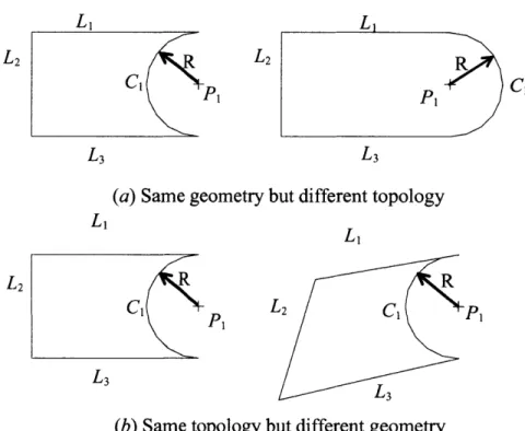
As stated previously, solid modelers store more information (geometry and topology) than wireframe or surface modelers (geometry only). Geometry (sometimes called metric information) is the actual dimensions that define the entities of the object. The geometry that defines the object shown in Figure 11 includes the lengths of lines, and, the angles between the lines, and the radius R and the center of the half-circle. Topology (sometimes called combinatorial structure), on the other hand, is the connectivity and associativity of object
entities. It has to do with the notion of neighborhood; that is, it determines the relational information between object entities. The topology of the object shown in Figure II can be stated as follows: Lishares a vertex (point) with L2and; L2shares a vertex with and L3; L3shares a vertex with C1and; and do not overlap; PIlies outside the object.
L1 L2 CL p1 L3 R P1 C
(a) Same geometry but different topology
L2 R C1 L3 (b) Same to R po L2 C P Z L3
pology but different geometry
Figure 11: Difference between geometry and topology of an object
Based on these definitions, neither geometry nor topology alone can completely model objects. Wireframe and surface models deal only with geometrical information of objects, and are therefore considered incomplete and ambiguous. From a user point of view, geometry is visible, and topology is considered to be non-graphical relational information that is stored in solid model databases and is not visible to users.
In context of mechanical assembly topology has an entirely different meaning, referring to the relations between parts in assembly. In the above discussion, it is important to realize that topology is described with respect to a part and not topology with reference to assembly.
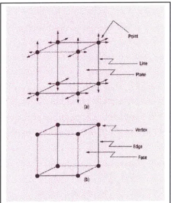
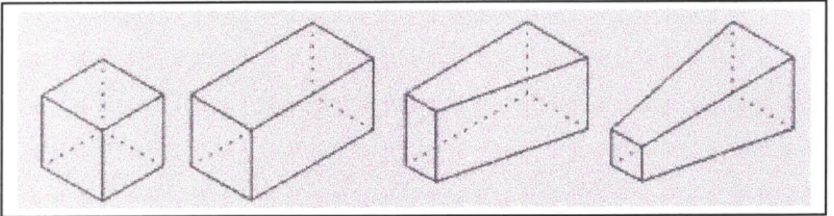
Consider the simple cube shown in Figure 12. Three types of geometric elements define the cube: points, lines, and planes. Eight points define twelve lines that in turn define six planes. The topological definition of the cube specifies how the geometric elements are bounded and form topological elements. The topological definition of the cube, then, is a region of space bounded by six planar faces, bounded by their intersecting edges and connected to each other at their edges. The edges are derived from the intersecting faces. The edges are bounded by vertices (points of intersection between one or more edges) and connect to each other at their common vertices. While the geometric elements of the cube consist of points, lines, and planes, the topological elements consist of faces bounded by derived edges and vertices and how those faces, edges, and vertices relate.
-4I-Figure 12: The geometric (a) and topological (b) elements that define a simple cube
The topological definition doesn't necessarily change if the geometric definition changes. In the case of the simple cube, parametric changes to its geometry result in a topology
definition that is unchanged. As shown in Figure 13, one can modify a cube in many ways and still maintain its original topology.
Figure 13: Topologically Same and Geometrically different Solid Models
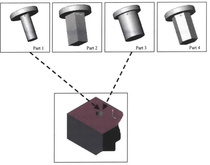
Extracting topological information from the CAD database can provide helpful information in assembling parts as shown in the Figure 14. In this example the assembly environment consists of 4 pegs and a cylindrical hole in one of the parts in the same assembly environment. Two out of four parts (Part 1 and part 3) have cylindrical shafts. Third peg (Part 2) has a rectangular shaft while the fourth (Part 4) one has hexagonal shaft. Since the topology of the hole is cylindrical, parts having cylindrical shaft as its topology can only be assembled. With the topological information itself, it can be decided that Part 2 and part 3 can't be assembled with the hole, while Part 2 and Part 3 holds chances of getting assembled with the hole feature. It is important to note that topological information is insufficient to determine which one pf Part 1 and Part 2 can be assembled with the hole feature.
Part 1 Part 4
I
I
I
I
Figure 14: Using topological information for automating CAD assembly
4.2.3 Geometry Driven CAD Assembly
Contours, faces, edges, corners, geometry of faces, (circle, rectangular, etc., and for 3-D: sphere, Cuboids) and other attributes such as Thread type (Right hand or Left hand, pitch, TPI, etc.), offset etc. constitute geometry. Grupen et al [19] worked on the use of geometric data integration techniques as a means to have formal criteria for recognizing free-form surfaces in 3-D object.
Some decisions about the assembly can be made right away knowing the high-level information about geometry. For example, if one part (or rather the contour being assembled) is prismatic and another one is non-prismatic, the parts cannot be assembled. A
gear tooth profile (involute) has to mate with another tooth profile (involute) of a gear. A large number of such examples can be found.
Thus "Geometry Driven CAD Assembly" shows promise for assembly automation.
4.2.4 Functionality Driven CAD Assembly
In physical world, one of the most important factors that affect assembly decisions is the function that a part performs. Assembly is not just specifying constraints. Rather, the aim is to put parts together to achieve certain desired function(s). In that sense, each part of the assembly, its various subassemblies and the assembly as a whole serve some specific function(s).
For example, a spur gear in an assembly environment has to mate with a spur gear to transmit torque. We typically would not have an unmeshed gear in the assembly. Similarly, we have rack and pinion pair (where the rack length axis has to be perpendicular to pinion axis and the tooth profile should be touching each other), bevel gear pairs with tooth profile touching and axes perpendicular; piston-hole pair where the axes of both match) etc. Another example includes the functionality of a screw. The function of a screw is to fasten two or more parts together.
As seen from the aforementioned examples "Functionality Driven CAD Assembly " can also be helpful in automating assembly.
4.2.5 Feature Driven CAD Assembly
Feature based design and feature recognition have been researched extensively for the last two decades [20]. Recognition of part features such as a hole, shaft, groove, slot, or pocket is important for performing assembly operations. Every part is composed of many features that, in many cases, govern the assembly. In the mid 1980s, researchers worked on extracting feature information from 3-D CAD data. For example, Henderson, R [21] developed algorithms that are capable of identifying and extracting features of 3-D CAD data and organizing the resultant information into a feature graph. Vandanbrande [22]
worked on recognition of machinable features using artificial intelligence and computational geometry techniques. Requicha et al [23] developed a system for generating machining feature recognition of mechanical parts by using the information available in the solid model of a part, its design features, tolerances and attributes etc. Currently, most CAD systems allow users to make parts based on features and then save the information in a feature-based
format. This makes the process of feature recognition rather trivial.
Thus, assembly automation driven by feature(s) of parts also shows promise. Let us again consider the example of the assembly described in chapter 3 (Figures 3, 4, 5 and 6). The peg has a cylindrical shaft feature while the cone has conical surface. Correspondingly, the base part has a conical and cylindrical hole. Based on the feature-based analysis, it is obvious that conical surface of the cone has to mate with conical hole feature of the base part and the circular shaft of the peg has to mate with the circular hole feature of the base part. The assembly process is shown in Figure 15.
Feature= Conical surface
Feature=-Conical hole
Feature= Circular shaft
Figure 15: Feature based approach for automating peg, cone and base part CAD assembly
4.2.6 Orthographic Views (projections) Driven CAD Assembly
Orthographic views are easy to generate and they contain relatively less data than three-dimensional objects. For example, in CATIA@, once the solid part model is made the orthographic views can be obtained by selecting 'Drafting' option (From pull down menu of CATIA® session: Start- Mechanical Design 4 Drafting). One of the advantages of going
from 3-D database to 2-D database is that we have low volume of data which may be easier to analyze and can provide useful pieces of information in making decisions for assembly.
Figure 16 illustrates the orthographic views (front, top and left side view) generated for an angle bracket in CATIA®. In addition, depending upon the selection of preferences, six views (front, bottom, rear, top right side and left side view) can also be generated.
Ii IiL FIrO4t view *~1 - -l Too view IScale: 1: 1 -____-- -- -- ---- --- ___ r -- -- --- I Lef Ii I Ile
Figure 16: Orthographic views generated in CATIA®
Depending upon the extent to which the orthographic views are analyzed, various part's information can be found by generating three-dimensional objects in many cases. The topic of generating solid 3-D objects from 2-D orthographic views has been studied for a number of years. Back in 1973, Idesawa [24] laid the foundation for the research topic "3-D objects from orthographic views." To date, researchers have come up with an array of algorithms to
generate 3-D objects from the user specified orthographic views. In 1997, Masuda [25] proposed an efficient method for converting orthographic projections into solid models based on non-manifold topology and assumption-based truth maintenance system (ATMS). They also describe an error recovery method for incorrect orthographic projections that may arise due to human errors. However, in this case, since the orthographic view is generated by the CAD package itself, it is certainly a correct orthographic projection of the solid under consideration.
Apart from obtaining solid parts from 2D part drawings, research has also been done to obtain solid parts from 2D assembly drawings. Tanaka et al [26] proposed a methodology for decomposing a 2D assembly drawing into 3D parts drawings using a set of solid element equations. They have tested the methodology on various 2D assembly drawings.
The limitation of using orthographic views is that most of the research in the area of generating 3-D solid objects from 2-D projections is limited to orthographic projections consisting of straight lines, circles, or ellipse, and that solid models consist of planes, cylinders, cones, spheres ([25] and [27]). This shows that all the information about a generic solid model from its orthographic projections may not be extracted.
Since the organization and representation of internal data corresponding to a solid model is CAD system specific, it is important to extract information as per the CAD specific representation of orthographic views. If all the solid model parts are made in the same CAD package, it is feasible to write an Application Programming Interface (API) that extracts data for assembly of parts within the same package. For heterogeneous CAD environment, it may be useful to save the 2D file as an image file, and then apply pattern recognition software or use any of the many image-processing tools to search for patterns that can help in assembly. One of such tools is MATLAB@2 [28]. People have worked extensively on developing various algorithms and technique for 2D shape recognition. Mohan and Ozcan [29] worked on shape recognition using genetic algorithms. Cai and Liu [30] developed a
2 MATLAB@ is an integrated computing environment that uses a combination of visualization, graphics and a
high level programming environment
technique for using Markov models with spectral feature for recognizing 2D shapes. Neural Networks also provide powerful tools for solving the shape recognition problem. Seibert and Waxman [31] worked on recognizing 3D objects from multiple views in a neural system.
Chin and Teh [32] developed a local feature aggregation method for recognizing two-dimensional objects based on their CAD models. Their methodology is capable of handling objects that are translated, rotated, scaled or occluded.
Apart from orthographic views, skeletal representations of a 3D object, as described by Gursoz et al [33], can also be helpful. In skeletal representations, solid objects are represented by lower dimensional entities with associated thickness. In 2D, this means that objects are represented by line and each point of line has an associated thickness. Figure 17 shows an example.
Figure 17: The lower figure represents skeletal representations of the figure above
4.2.7 Library Driven CAD Assembly
One of the ways our brain works is that it tries to match any new object with familiar objects and then apply the same rules of interaction as it had applied with the object that most closely matches the new object.
Similarly, in CAD systems, we can define various standard parts/ features, set up rules of interaction in assemblies, and put this information in a library. Once the CAD system
encounters a new part, it will try to look for the exact (close) match with the previously stored parts/features, and then will apply the same rules for interaction as it did for those parts in the assembly. We will call this "Library Driven Assembly ".
For example, we can have a set of guiding rules for Peg and Hole Assembly, which require something matching the centerline and moving along the centerline to place it appropriately.
Especially for subassemblies consisting of standard parts, library driven automated assembly is easy to implement given the rules governing the assembly are provided in the knowledge base. As an example, lets consider assembly of a nut, bolt, washers (two) and hole feature (formed out of assembling two or more parts). The standard way that governs assembly is shown in the following Figure 18.
Waser
aole
Fet%*reNut
Figure 18: Set of assembly rules for standard library parts
Similarly, other rules governing assembly of standard parts can be defined.
4.2.8 Constraints Driven CAD Assembly
By considering constraints, an assembly (subassemblies, set of mating conditions) can be broken down into three main categories depending upon DOF (degrees of freedom):
Under Constraint: Some DOF is left unspecified in assembly. Over Constraint: Some DOF is constrained more than once.
Properly Constraint: Each DOF is specified once and the system is well defined.
Most mechanical assemblies are Properly Constraint systems, although some may be Over
Constrained or Under Constrained systems. Nevertheless, a designer/assembly engineer
knows before hand which part is properly/over/under constraint. Specifying such information before the assembly phase (possibly by associating information with the part itself) will help in the automation of assembly.
Hence, exploring "Constraint Driven Assembly " seems promising.
In an assembly, mating is important; and the mates between the parts reduce the DOF of both parts relative to one another, though the combined parts does not lose any DOF. It can be observed from the original example, involving a round peg, a conical peg and the base part, that the parts become constrained in assembly and thereby lose DOF. This is, in general, true.
The DOF of parts in an assembly also gives us other useful pieces of information. If the DOF of any part is 6, the part has not been assembled at all and is free. This refers to incompatibility of the part for the assembly process.
DOF=O shows that the assembly is a "Structure" and hence has no movable parts. For O<DOF<6 of a part, the only inference one can draw is that the part is free to move/rotate with one or more DOF. By analyzing DOF, part-by-part, the designer/engineer/assembly person can determine whether the design intent is matched or not, or it can serve as a checkpoint for design part of assembly analysis.
In an assembly consisting of n parts,
Maximum DOF the system can have =6n (completely unassembled) Minimum DOF for assembly =0 (Structure, e.g., a bridge)
The concept developed in this thesis does not depend on the assembly sequence. It just concerns the final assembly. The order in which parts are assembled is independent of mating constraints between parts.
The application of DOF associated with parts can be implemented in two ways. First, DOF can be used in deciding which parts go where. If it is clear to a designer that a particular part has to be, lets say, over constrained, then he attaches an attribute to that part indicating that the part is over constrained. This attribute will not let the part be assembled where it is either properly constrained or under constrained. Otherwise, the assembly engineer can use the DOF information in the verification step as shown in Figure 19.
Techniques based on DOF analysis have also been used to solve the problem of determining the positions and orientations of a set of rigid objects that satisfy a set of geometric constraints [34].
4.2.9 Other Factors that are Helpful for Automating CAD Assembly
The above-mentioned eight factors are the major factors that can help in the automation process; but by no means, this is an exhaustive list of factors.
Another factor that can be helpful is the part the material. Knowing and specifying that a part of only a particular material should assemble with another part can be a factor driving assembly. For example, consider an assembly environment having metallic as well as rubber washers with the same dimension. In this case, the material of the part is the only driving factor in the assembly and the assembly engineer can specify the material based decision-making rules in the Knowledge base/rules (as described in Chapter 5), which will help in automating the assembly process.
Other factors include surface finish of a part, names of parts, properties like mass, surface area, volume, center of mass, moment of inertia, supplier of part, manufacturing process, manufacturing location of the part, etc. Identifying and specifying other helpful factors depends upon the part as well as the nature of assembled product.
4.3 Proposed Methodology
An overview of the proposed automated assembly algorithm (AAA) is as follows in Figure 19.
Feedback for reconsideration based on factors
KO
Parts partially Verification Assembled OK CAD assembly engineer inputs to complete assembly Complete Assembly
Fig 19: Basic flow chart of automated assembly in a CAD package
The parts are assembled based on certain rules contained in the knowledge base. The pseudo code for one of the rules (assembling hole and shaft feature) may look like as shown in Figure 20.
If (Hole dimension= shaft dimension within the tolerance limit)
Figure 20: Pseudo code for assembling hole-shaft feature
Factor 1 Factor 2 -Factor N Lr2 Knowledge Base/Rules No'
Either all the rules are applied at once or they can be applied one by one or in combinations. For a product with small number of parts, all the factors can be applied at once. As the number of parts increases, the complexity of decision-making process grows exponentially. So, with products containing many parts (say >15-20), it may be helpful to apply the factors one by one, and proceed further depending upon its effect. Depending on the outcome of the application of various factors/rules, the assembly engineer can decide if the particular rule is helpful in assembly or not. These rules, when applied to a set of parts, give us an assembly. In many cases this may give us an assembly where parts are partially assembled-let's call it a loose assembly. This loosely assembled system is subjected to verification, and feedback is sent to knowledge base as shown in Figure 19 and the parts gets reassembled in a better way.
For example, if there are parts overlapping with each other beyond tolerance limits, then it is an incorrect assembly. In this case, either one of the parts is set free and taken out of assembly, or the part is assembled in a way that gives a better-suited assembly configuration. After this, the CAD assembly engineer resolves ambiguities, verifies the system, and then parts will be assembled together in the desired way. Depending upon the specific nature of the product, some weighted criteria may on the factors to govern the assembly.
Researchers have worked on knowledge-based systems for automated assembly planning for robotics applications. Park et al [35] worked on a computer-aided planning system for automated assembly cells which uses a product description to generate assembly sequences and finally robot programs. Deitz et al [36] has worked on utilizing the knowledge of assembly operations and the capabilities of future equipment for planning an assembly cell.
5
Extracting Part Information From CATIA Solid Models
5.1 Introduction to CATIA®
CATIA@ is one of the leading CAD high-end software packages that handles both surfaces
and solids. CATIA® (Version 5 Release 6) is organized into a collection of workbenches,
each dedicated to a specific application area, viz. Part Design, Sketcher, Wire frame and Surface, Assembly Design, and Generative and Interactive Drafting. CATIA's Part Design Workbench contains solid modeling tools to design parts using features. CATIA's feature classes include sketch-based features, dress-up features, surface-based features, and transformation features.
Sketch-based features include pads, pockets, shafts, grooves, holes (standard and threaded), ribs, stiffeners, lofts, etc. Each feature group covers a wide range of types. For example, holes support a wide range of geometric configurations, including simple, tapered, counter bore, counter drill, and countersink, all from a single dialog box. Extension types include blind, up to next, last, plane, and surface. CATIA's dress-up features include fillets, chamfers, draft, parting lines, shells, thickness, and threads. CATIA's surface-based features include splitting a solid with a surface, adding thickness to a surface, closing an open set of surfaces, and trimming a solid with a surface. Transformation features allow translating, rotating, scaling, and mirroring solid bodies. Rectangular, circular, and user-defined feature patterns can also be created.