Publisher’s version / Version de l'éditeur:
Canadian Metallurgical Quarterly, 44, 3, pp. 369-378, 2005-07-01
READ THESE TERMS AND CONDITIONS CAREFULLY BEFORE USING THIS WEBSITE. https://nrc-publications.canada.ca/eng/copyright
Vous avez des questions? Nous pouvons vous aider. Pour communiquer directement avec un auteur, consultez la
première page de la revue dans laquelle son article a été publié afin de trouver ses coordonnées. Si vous n’arrivez pas à les repérer, communiquez avec nous à [email protected].
Questions? Contact the NRC Publications Archive team at
[email protected]. If you wish to email the authors directly, please see the first page of the publication for their contact information.
Archives des publications du CNRC
This publication could be one of several versions: author’s original, accepted manuscript or the publisher’s version. / La version de cette publication peut être l’une des suivantes : la version prépublication de l’auteur, la version acceptée du manuscrit ou la version de l’éditeur.
Access and use of this website and the material on it are subject to the Terms and Conditions set forth at
Numerical Simulation of Flow, Temperature and Composition
Variations in a Galvanizing Bath
Ajersch, F.; Ilinca, F.; Hétu, J. -F.; Goodwin, F.
https://publications-cnrc.canada.ca/fra/droits
L’accès à ce site Web et l’utilisation de son contenu sont assujettis aux conditions présentées dans le site LISEZ CES CONDITIONS ATTENTIVEMENT AVANT D’UTILISER CE SITE WEB.
NRC Publications Record / Notice d'Archives des publications de CNRC:
https://nrc-publications.canada.ca/eng/view/object/?id=eee6b43a-3f44-48b7-8f93-c0e0410833fb https://publications-cnrc.canada.ca/fra/voir/objet/?id=eee6b43a-3f44-48b7-8f93-c0e0410833fb369
NUMERICAL SIMULATION OF FLOW, TEMPERATURE
AND COMPOSITION VARIATIONS IN A GALVANIZING BATH
F. AJERSCH1, F. ILINCA2, J.-F. HÉTU2and F. GOODWIN3
1École Polytechnique de Montréal, Montréal, Quebec, H3C 3A7, Canada 2Industrial Materials Institute, National Research Council
Boucherville, Quebec, J4B 6Y4, Canada
3International Lead Zinc Research Organization
Research Triangle Park, NC, U.S.A.
(Received in revised form February, 2005)
Abstract — The modern hot dip galvanizing operation is a complex process subject to a number of
configurational, physical, chemical and kinetic parameters. Small decreases in temperature can precipitate intermetallic dross particles, which can be entrained in the flow towards the strip leading to surface imperfections. The numerical simulations carried out in this study clearly define the spatial distribution of velocity, temperature and compositional variation in the bath. The modeling of the transient effects during ingot melting and non-melting periods have also identified the critical periods and zones within the bath where dross formation can occur within an operating cycle.
Résumé — L’opération moderne de galvanisation à chaud est un procédé complexe exposé à plusieurs
paramètres configurationnels, physiques, chimiques et cinétiques. De petites diminutions de température peuvent précipiter des particules intermétalliques de scories, lesquelles peuvent être entraînées dans l’écoulement vers la bande, conduisant à des imperfections de surface. Les simulations numériques effectuées dans cette étude définissent clairement la distribution spatiale de la vitesse, de température et de la variation de composition dans le bain. La modélisation des effets transitoires lors des périodes de fonte et d’absence de fonte du lingot a également identifié les périodes critiques ainsi que les zones dans le bain où la formation de scorie peut se produire à l’intérieur d’un cycle d’opération.
INTRODUCTION
More than half the world’s production of zinc is used for general and continuous galvanizing in the coating of steel products and the future outlook indicates that this trend will continue to increase with the development of new market applications [1]. By far the most important product is hot dip galvanized steel sheet used for automobile body manufacture. As a result of the ultralight steel automobile body (ULSAB) initiatives over the years, the steel makers have been able to supply automobile manufacturers with coated sheet having excellent corrosion resistance, ready-to-paint surface quality, good weldability and formability. This high quality coated steel is a very important and large volume product linking steel producers with zinc suppliers around the globe. New types of high strength steels such as dual phase and transfor-mation induced plasticity (TRIP) steels are being introduced to further decrease the vehicle weight while maintaining the necessary impact resistance. Thinner, more adherent coatings for these new steels are a challenge to the galvanizers. Since
these products are a major factor in the profitability of all steel sheet producers, the technology and process control of the galvanizing operation is of primary concern [2]. Process sim-ulation of the coating operation, by quantifying the influence of configurational and operational parameters on dross for-mation within the bath, has been found to be a very powerful tool for zinc bath management. The analysis of these simula-tions results in attaining more predictable coating characteris-tics as well as in increasing the productivity of the process.
DESCRIPTION OF THE PROCESS
The hot dip galvanizing process is a complex metallurgical process where a steel strip of various width and thickness is continuously coated by rapid immersion in a zinc alloy bath normally maintained between 450 and 480 °C. Contact times range between 2 and 6 seconds and depend on pot size, hard-ware arrangement and line speed which is limited by sheet thickness (thin strip can be processed at a higher speed than
Canadian Metallurgical Quarterly, Vol 44, No 3 pp 369-378, 2005 © Canadian Institute of Mining, Metallurgy and Petroleum Published by Canadian Institute of Mining, Metallurgy and Petroleum Printed in Canada. All rights reserved
thick strip). The interfacial reactions occur almost immediate-ly after immersion by forming an inhibition layer. On exiting from the bath, the excess zinc is deflected back into the bath by means of air knives, leaving a thin coating on the steel sheet. Coatings for automobile products generally measure about 10 to 15 mm (70-100 g/m2on each side), whereas the
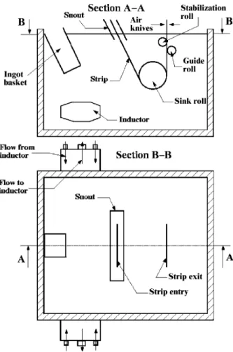
construction materials have considerably thicker coatings. Beyond the air knives, the sheet rises vertically and is cooled to an ambient temperature for the galvanized product or it can pass through a temperature controlled galvannealing section where further reactions occur in the coating. Generally, both types of products can be produced on the same line where the galvannealing unit can be put into place as required. An illus-tration of a typical modern galvanizing bath is shown in Figure 1.
Role of Aluminum in the Coating Process
Aluminum additions to the galvanizing bath are essential in order to obtain an adherent coating with good formability. Concentration levels for the galvanneal product are in the range of 0.11 to 0.13% Al and up to 0.30% Al for the
galva-nized product. Adherence of the coating is generally mea-sured using “powdering” tests according to a specific bending mode where the amount of non-adhering particles of the coat-ing are quantified. The rapid reaction of the Al in the bath with the steel forms an inhibition layer of Fe2Al5 generally
less than 1 mm thick which is both adherent and deformable as opposed to the iron zinc intermetallic phases which are much more fragile. On exiting the bath, this solid layer is cov-ered with an entrained liquid layer of the alloy at the bath composition. The air knives control the coating thickness by a variation of air pressure and gap width from the strip. The amount of Al in the inhibition layer increases with the Al con-tent in the bath up to 0.20% as was shown by Hertveldt et al.
[3] as well as with steel composition and temperatures of the steel strip and the zinc bath [4]. Galvanized products for exposed applications are frequently produced in baths con-taining 0.25% and higher aluminum contents. Addition of zinc ingots with Al contents higher than the bath composition are therefore necessary to maintain a steady state operation. The layer of Fe2Al5needs to be sufficiently thick to ensure
coverage of the entire surface. Excessive thickness is unde-sirable since it was clearly shown by Bilello et al. [5] that the
coating ductility decreases with the increasing thickness of the Fe2Al5 layer. The galvanizing bath therefore can be
con-sidered to be a reactor where a product layer Fe2Al5
inter-metallic and Fe-Zn-Al alloy are continuously removed from the bath. Linares et al. [6] have described the reactor where
zinc and aluminum are transported from the ingot to the steel by the induced flow of the bath from the movement of the strip and immersed equipment. It can generally be stated that the bath is iron saturated due to the continuous contact with the steel. Make up ingots of zinc alloy are in the range of 0.50 to 1.0 wt% Al depending on the type of product or operation. Local decreases in the temperature near the melting ingot sur-face reduce the solubility of both iron and aluminum and are considered to be one of the primary sources of dross particles which can nucleate and grow. Control of bath temperature is therefore of primary importance in order to prevent this pre-cipitation phenomenon during the production of high quality coatings.
The thermodynamics have been investigated in a num-ber of studies [7-9]. A review of the thermodynamic data and solution models has also recently been presented by Costa e Silva et al.[10]. Tang [8] measured the aluminum and iron
solubility in molten zinc as a function of temperature at 450, 460 and 470 °C by atomic absorption spectroscopy. Solid intermetallic compounds zeta (z), delta (d) and eta (h) phases were identified and characterized using electron microscopy and the data was analyzed using solution models. McDermid and Thompson [11] have also studied the relationship of tem-perature on iron solubility using available experimental data and rigorous thermodynamic analysis and have found slightly different phase boundaries. The comparison of the solubility equations for the galvanized region (Al contents above the ‘knee’ point) agrees to within 95% with the data of Tang [8], whereas the invariant point in the galvanneal region (liquid-d) was found to be at a much lower Al content. A comprehensive
NUMERICAL SIMULATION OF FLOW, TEMPERATURE AND COMPOSITION VARIATIONS IN A GALVANIZING BATH 371
model for this region of the phase diagram, shown in Figure 2 for liquidus temperatures from 450 to 480 °C, was found to be very useful for galvanizers. Tang’s version of the diagram [8,12] is well established in the industry and is used by a large number of galvanizers in their daily operations [13]. This rep-resentation of the Fe and Al solubility is used to calculate the effective (dissolved) Al content in the bath for each isotherm. Assuming Fe saturation, the total Al content of a bath there-fore corresponds to the dissolved amount plus any excess amount associated with the formation of either d or h phases.
PROCESS SIMULATION
Previous simulations progressed from laminar to turbulent flow models where the effect of line speed, strip width and induction mixing has all been quantified for isothermal bath conditions operating at a steady state. It has become clear that the flow is three-dimensional due to the complex geometry of the immersed hardware. This still only simulates the condi-tion for periods of the process when no make up ingots are added to the bath. However, when ingots are added to replen-ish the liquid metal taken out by the strip, the bath can no longer be considered to be isothermal. During this period, the induction heating rate is increased to adjust to the heat demand of the melting ingot thereby increasing temperature variations in the bath. The temperature at the inductor exit is higher and the region at the melting surface of the ingot is lower than the average bath temperature. Since the liquid zinc alloy densities are very sensitive to the temperature varia-tions, it is anticipated that temperature variations in the bath would affect the overall flow due to natural convection, espe-cially in regions where forced convection is small. This occurs in regions away from the moving strip and immersion rollers which are significantly affected by the temperature variations. The simulations show the importance of these tem-perature variations on the flow within the bath resulting from the melting of an ingot as compared to the isothermal case. The bath configuration used in the study is the same as that used for the previously reported isothermal calculations [14]. Heat losses through the pot sidewalls, bottom and bath
sur-face are taken into account in the heat balance so that the overall average bath temperature remains relatively constant at 460 °C.
The numerical model assumes that the melt behaves as a Newtonian fluid and that the flow is turbulent. Turbulence is modelled by the k - e model of turbulence and buoyancy
effects are considered through the Boussinesq approximation. Time dependent effects are included and solutions were obtained at different time intervals. The momentum and con-tinuity equations are as follows:
(1)
(2)
where is the particular derivative, g◊(u) = (—u+—uT)/2 is the strain rate tensor, r is the density, and m is
the fluid viscosity. In the last two terms of the momentum equations, which describe the buoyancy effects, g is the grav-ity, T is the temperature, cAlis the aluminum concentration, r0
is the density at the reference temperature T0and reference
aluminum concentration cAl0, while bTand bAlare the thermal and aluminum concentration expansion coefficients defined as (3)
(4) The turbulent viscosity mTis computed using the standard k
-e mod-el of turbul-enc-e [15]
(5) For this model, the turbulence quantities are the turbulence kinetic energy k and its dissipation rate e. The transport
equa-tions for k and e are
(6)
(7)
where P is the shear production term defined as
(8) and G accounts for the effect of the buoyancy on the
produc-P( )u =mT
[
— — + —u:(
u uT)
]
r e m m s e re e e e e D Dt P G k T = — ◊ Ê + ËÁ ˆ ¯˜— È Î Í Í ˘ ˚ ˙ ˙+ + -C k C l 2 2 ( ) r m m s r e D Dt k P G T k k = — ◊ Ê + ËÁ ˆ ¯˜— È Î Í Í ˘ ˚ ˙ ˙+ + -m r e m T 2 C k = b r r Al= -∂ ∂ Ê ËÁ ˆ ¯˜ 1 cAl p T, b r r T = -∂ ∂ Ê ËÁ ˆ ¯˜ 1 T p c Al , D Dt = t ∂ ∂ + ◊ —u — ◊ =u 0 r m m g r b r b 0 0 0 0 2 0 D Dt p T T c c T T Al Al Al u u g g = -— + — ◊ + - - - -[ ( ) ˙( )] ( ) ( )tion of turbulence.
(9) The constants sk, se, Cel, Ce2and Cmare as follow [15]
sk = 1.0, se = 1.3, Cel = 1.44, Ce2= 1.92 and Cm= 0.09
Increased robustness of the solution algorithm is obtained by solving the turbulence equations for the loga-rithms of turbulence variables [16]. In such a way, the posi-tivity of turbulence variables is enforced resulting in increased accuracy and a faster solution approach. For more details on the solution algorithm, see Ilinca et al. [17].
Temperature T is obtained by solving the energy
equa-tion
(10) where cpis the specific heat and l is the thermal
conductivi-ty. The turbulent thermal conductivitylTis computed from
(11) where PrTis the turbulent Prandtl number considered equal to
unity.
Aluminum and iron concentrations ci, (cAl for the
alu-minum concentration and cFefor the iron concentration), are
obtained by solving the mass transport equations
(12) where D is the molecular diffusion coefficient. For this work,
we consider that the Schmidt number Sc = m / rD is equal to
unity. The turbulent diffusion DTis computed from
(13) where ScTis the turbulent Schmidt number considered equal
to unity.
Velocity wall functions were used to model all solid sur-faces including the pot walls, the moving strip and the rotat-ing sink and stabilizer rolls. Heat transfer through all surfaces was modelled using convection boundary conditions and a temperature wall function. The initial steady state tempera-ture in the bath is considered to be 460 °C. For the aluminum and iron transport in the bath, the boundary and initial condi-tions must also be imposed for the aluminum and iron con-centrations. The initial aluminum concentration in the bath is considered to be 0.14% in weight and the bath is considered to be saturated in Fe at the initial temperature of 460 °C [8]. Boundary conditions are specified on the strip and the inlet section (inductor inlet) as well as on the solid boundaries (walls) and top surface of the bath. Simulations were done for the cases with and without the presence of an ingot. When the
ingot is present in the bath, the inductor power is considered to be at 100%. The inductor power is decreased to 20% when no ingot is present in the bath. The inductor flow rate and temperature increase for these settings are taken from the data of the previous validation study [14]. The liquid zinc from the inductors enters the bath at 0.75 m/s and is heated to 20 °C above the temperature of the melt entering the inductor when 100% of the power is considered and at 0.4 m/s and 8 °C tem-perature increase when only 20% of the inductor power is used [18,19]. A heat balance calculation was carried out to assure that the average bath temperature returned to the initial condition after the ingot addition and melting cycle followed by a period of no ingot addition. This is illustrated in Figure 3 and in Figure 4 covering a two-hour period of simulation. The heat lost by the bath is higher during the period of melt-ing melt-ingot as shown in Figure 3, but also the heat input from
D Sc T T T = m rDc Dt D D c i T i = — ◊[( + )— ] lT m T p T c = Pr rc DT l l Dt T p = — ◊[( + T)— ] G T T T = m b ◊ — Pr g
Fig.3. Heat lost by the bath.
Fig.4. Total heat balance in the bath. r
inductors is higher during this period. Figure 4 indicates that during the ingot melting period, the bath has a positive total heat balance, while during the period at lower inductor power, the bath loses heat.
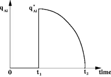
Since ingots are added to the bath at ambient tempera-ture, no aluminum is transferred to the bath until the ingot reaches the melting point. This was found to take six minutes [20]. The melting time is therefore 14 minutes during which all the aluminum and zinc in the ingot is transferred in the bath. Hence, the effective ingot mass flux is
(14)
with t1=6 min and t2=20 min (see Figure 5) and q*Alis the
ini-tial flux of Al at t=6 min which is 2.143 times the average Al
flux calculated for a total melting time of 20 minutes. The mass flux on the ingot surface for the iron concentration equa-tion takes into account the fact that the ingot has no iron in its composition.
Aluminum consumption on the strip surface is assumed to take place on the first 0.35 m of the strip from its entry in to the bath (corresponding to 0.2 seconds at a strip velocity of 1.75 m/s). The overall aluminum concentration of the coating is considered to be 0.4% by weight for a coating weight of 60 g/m2(0.06 kg/m2) per side. The mean aluminum consumption
flux is given by
(15) The mass flux is (qAl)strip= -0.3cAlkg/(m2s) for a strip velocity
of 1.75 m/s with cAl = 0.4. Similarly, an iron mass flux is
imposed on the strip surface to take into account the iron dissolution. The iron dissolution rate was considered to be
constant at 120 mg/m2 of coil [21] throughout the coating
process.
Since the aluminum and iron solubility in the bath varies with temperature, any excess aluminum will be present in the form of precipitates of Fe2Al5(top dross). Both dissolved
alu-minum and precipitated alualu-minum were calculated.
NUMERICAL RESULTS
The computational domain is illustrated in Figure 6. All com-putations were carried out using the IMI CFD solver. The computational domain was discretized using 4-node tetrahe-dral finite elements. The mesh has 64,522 nodes and 366,949 elements. Figure 7 illustrates the finite element discretization. Since the bath geometry is symmetrical, only half of the domain was considered. Constant material properties have been used to perform the analysis. The material properties for a Zn+0.15% Al at a temperature of 460 °C are: density r=6600 kg/m3, laminar viscosity m=0.004 Pa◊s, specific heat cp=512 J/ Kg◊K, thermal conductivity l=60 W/m◊K, thermal
expansion coefficient b=1.666◊10-4K-1and aluminum
concen-tration expansion coefficient bAl=1.44◊10-2.
( ) . / . q kg m m V c Al strip = - strip Al 0 06 0 35 2 ( ) , , q t t q t t t t t t t Al ingot Al = < -
(
-)
-(
)
È Î Í Í ˘ ˚ ˙ ˙ < < Ï Ì Ô Ó Ô * 0 1 1 1 2 2 1 2 1 2NUMERICAL SIMULATION OF FLOW, TEMPERATURE AND COMPOSITION VARIATIONS IN A GALVANIZING BATH 373
Fig. 5. Al mass flux on the ingot surface during the ingot melting period.
Fig. 6. Computational domain.
Fig. 7. Finite element discretization. Guide and stabilization
roll arms Stabilization roll Guide roll Bath height 2440 mm Sink roll Snout
Strip half width 750 mm Strip velocity 1.75 and 3.0 m/s
{
Ingot basket
Symmetry mid plane Z=0
Inductor
Zinc bath half width 1900 mm Zinc bath length
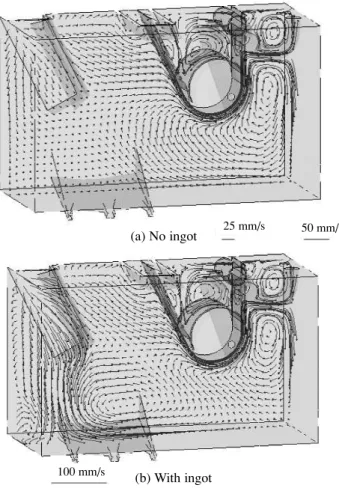
Velocity vectors in a plane parallel to the symmetry plane are shown in Figure 8. When no ingot is present (Figure 8a), the natural convection term makes little difference in this plane since only the liquid zinc cooled on the left wall moves down-ward because of the higher density. In both cases, thermal effects are localized near the inductors and the ingot and are very small near the sheet and roller region. Comparing these solutions, we can conclude that the flow near the ingot is dominated by ther-mal effects, whereas close to the sheet and rolls, the flow is determined by the movement of the steel sheet. When the ingot is present in the bath, the temperature also has a major influence on the flow as can be observed from Figure 9 illustrating the low velocity regions (zinc velocity lower than 0.01 m/s) with thermal effects.
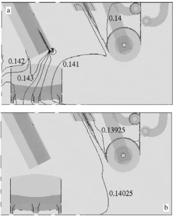
Figure 10 shows the distribution of temperature on the symmetry plane. With the ingot present, the cold zinc melting from the ingot flows to the bottom of the bath and the solution presents higher temperature gradients than for the case without the ingot. Figure 11 illustrates the distribution of total aluminum concentration on the symmetry plane with and without the ingot. With the ingot present, we observe a higher level of aluminum near the ingot and a lower level of aluminum near the strip entry where aluminum consumption takes place. Without the ingot, the aluminum concentration becomes very uniform except for a
region near the strip entry point where most of the aluminum is deposited. These results are in agreement with the global mass exchange that is driven by the aluminum addition from the ingot and aluminum consumption during the formation of the inhibi-tion layer in the region near the entry of the strip. Similar results are shown in Figure 12 for the iron concentration. Here, the region below the melting ingot has a lower iron concentration because the ingot has no iron, whereas at the strip entry point, the iron concentration is higher because of the iron dissolution
Fig. 9. Iso-velocity surface (smaller than 0.01 m/s) for the case with ingot present.
Fig. 10. Temperature distribution on the symmetry plane: a) with ingot (t=10 min) and b) no ingot (t=60 min) (increment between iso-values is 1 °C).
a
b
Fig. 8. Velocity vectors on a plane parallel to the symmetry plane. (a) No ingot
(b) With ingot
25 mm/s 50 mm/s
that occurs before the formation of the inhibition layer. At the end of the cycle (60 minutes), the iron concentration is relative-ly uniform with a slightrelative-ly higher concentration close to the strip near its entry point due to iron dissolution from the strip.
In order to illustrate the evolution of different variables during two complete cycles of 20 minutes with ingot melting and 40 minutes without the ingot, graphs were plotted for 4 spe-cific locations in the bath on the ingot side and for 4 locations on the strip exit side. These locations are illustrated in Figure 13.
Figure 14 illustrates the evolution in time of the temper-ature over two complete cycles. The initial tempertemper-ature is uni-form at 460 °C. As soon as the ingot is introduced into the bath (t=0), the temperature drops at the inductor/ingot side at the low centre and low side locations. The temperature rises at the up side location because inductors are running at a higher power projecting heated zinc towards the top surface of the bath. We can also observe that the temperature gradi-ents are higher on the ingot side and during the ingot melting period (t=0-20 minutes). Without the ingot, the temperature becomes more uniform with an initial correction between t=20 minutes and t=30 minutes. The stratification of temper-ature in the bath is due to buoyancy. On the strip exit side, the temperature at the four locations is more uniform and varies as the mean temperature. During the period at 100% inductor power, the temperature increases by 3 to 4 degrees and
decreases back to a temperature close to the initial tempera-ture at the end of each cycle.
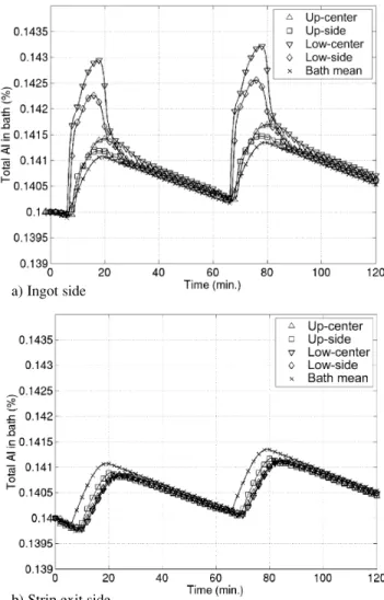
Figure 15 shows the evolution in time of the total alu-minum concentration. The total alualu-minum represents the amount that is in solution as well as the amount that is in pre-cipitated form. Subsequent calculations to differentiate NUMERICAL SIMULATION OF FLOW, TEMPERATURE AND COMPOSITION VARIATIONS IN A GALVANIZING BATH 375
Fig. 13. Location of points for plots in time (dimensions are in metres). Fig. 11. Total aluminum concentration on the symmetry plane: a) with ingot
(t=20 min) and b) no ingot (t=60 min) (increment between iso-values is 0.0005).
Fig. 12. Total iron concentration on the symmetry plane: a) with ingot (t=20 min) and b) no ingot (t=60 min) (increment between iso-values is 0.0001).
a
b
a
between the dissolved and precipitated form of aluminum assume that the rate of dissolution and precipitation are instantaneous. During the first 6 minutes, the ingot is brought up to the melting point. During this period, the alu-minum concentration decreases, especially near the strip, as aluminum consumption takes place on the strip without any supply from the ingot. When the ingot begins to melt (t=6 minutes), a sharp increase of aluminum concentration is observed on the ingot side. On the strip exit side, the increase is delayed by about 3 minutes corresponding to the time it takes for the zinc on the ingot side to reach the front (strip section) of the bath as a result of the overall bath flow. Validation tests using aluminum sensors to measure the vari-ations in aluminum level after the addition of brightener bars [14] gave nearly the same value of the time increment. During ingot melting, the total aluminum concentration in the bath is higher with a maximum value near the ingot surface at about t=14 minutes. On the ingot side, the differences between dif-ferent locations are more apparent resulting in higher values
on the low centre location and the lower values for the up cen-tre location. Flow from the ingot (rich in aluminum) reaches the low centre location first, followed by the low side, up side and finally up centre locations. This is in good agreement with the buoyancy driven movement of zinc [17]. On the strip exit side, the aluminum concentration is more uniform, since this area is mixed at a much higher intensity due to the roll and strip movement. Without the ingot, the aluminum con-centration becomes more uniform but still remains higher on the ingot side. During this period, the aluminum concentra-tion decreases constantly because of the aluminum consump-tion on the strip. Inside the snout, uniform aluminum concen-tration is observed except for the region near the centre of the inner side of the strip. This is indicative of a zone that does not readily mix with the zone in contact with the external side of the strip. In industrial practice, however, very little differ-ence is observed in the total aluminum content of the coatings on either side of the strip. The small differences of aluminum content in the regions of the bath in contact with the inner and outer surface of the strip do not seem to affect the total amount of aluminum to the overall coating.
Fig. 14. Temperature history during two complete cycles. a) Ingot side
b) Strip exit side
Fig. 15. History of the total Al concentration during two complete cycles. a) Ingot side
Figure 16 shows the evolution in time of the total iron concentration. Iron concentration increases throughout the operation due to iron dissolution from the strip, except for a small period during ingot melting when material with no iron content is introduced in the bath [22]. The initial iron concen-tration corresponds to the limit of solubility product of alu-minum and iron for 0.14 wt% Al content at the initial temper-ature of 460 °C and the total increase in the iron content is of only about 0.0005 wt% over two cycles.
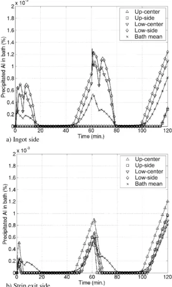
Figure 17 illustrates the concentration of aluminum pre-cipitated as Fe2Al5dross. This value is determined as the mass
of aluminum and iron above the temperature dependent limit of solubility product. Due to the sensitivity of the solubility of aluminum and iron in the bath as a function of temperature, moving particles of Fe2Al5can either grow by continued
precip-itation or dissolve in different temperature zones of the bath. When the ingot is immersed, we observe a sharp increase in dross formation on the ingot side. This is caused by the decrease in temperature which is highest at the low centre location. During ingot melting, dross is also formed as the aluminum rich
ingot dissolves in the bath. The ingot melting determines the for-mation of dross only in the region around the ingot. Finally, dross is also formed at the end of the cycle because of the over-all decrease in temperature. The numerical model clearly indi-cates that larger variations are observed on the ingot side. For an initial concentration of 0.14 wt% Al, dross is formed mostly at the bottom of the bath where the temperature is lower. The cal-culations also show that small quantities of dross are formed inside the snout representing only a very small fraction of the total dross formed.
CONCLUSIONS
The computed results for the specific cases illustrated show that forced convection flow is controlled principally by the movement of the immersed hardware and moving strip in the region of the NUMERICAL SIMULATION OF FLOW, TEMPERATURE AND COMPOSITION VARIATIONS IN A GALVANIZING BATH 377
Fig. 16. History of the total Fe concentration during two complete cycles. a) Ingot side
b) Strip exit side
Fig. 17. History of the precipitated Al concentration during two complete cycles.
a) Ingot side
bath where the temperature gradients are the smallest assuming that the entering strip and average bath temperatures are the same. Large temperature variations were observed for the condi-tion during ingot melting as a result of the large difference in tem-perature between the bath and the melting point of the ingot and because of the additional heat introduced by the inductors that is required for melting and maintaining the bath temperature at an average level of 460 °C. Flow in this region is dominated by a very significant contribution from natural convection.
It can be concluded that the calculated aluminum concen-tration gradients are much more pronounced at the ingot side during ingot melting, whereas a more uniform distribution occurs during the period when no ingot is present. A more uni-form distribution can be observed on the strip side compared to the ingot side due to the high degree of mixing caused by the rotating equipment in this region. The aluminum concentration as precipitated Fe2Al5also increases in the ingot melting zone
due to the decrease of temperature near the ingot surface and also because of the higher aluminum concentration of the ingot. The slight decrease of the iron content in this region has an opposite effect reducing the formation of dross. It is clearly shown that the heat input needs to be closely controlled during ingot melting to maintain a stable temperature in the bath. However, the inherent temperature gradients caused by ingot melting result in the precipitation of aluminum as Fe2Al5in the
cold regions of the bath. Entrainment of intermetallic particles is almost inevitable and good bath management requires a min-imization of dross formation.
Validations of numerical simulations have been carried out on an industrial bath as well as in a water model using laser Doppler velocimetry and particle image velocimetry (PIV) [23] showing good agreement with the experimental results. The advantage of the simulation lies in the possibility to cover a wide range of flow, composition and temperature variations within the bath and to be able to predict the localized formation of dross particles for the various conditions.
ACKNOWLEDGEMENTS
The authors would like to acknowledge particularly the International Lead Zinc Research Organization (ILZRO) and the industrial sponsors for funding this project. The authors also wish to acknowledge the contribution of Michel Perrault in creating the bath mesh for the simulation.
REFERENCES
1. Pocket Guide to World Zinc, 1998, International Zinc Association, Belgium.
2. A. Stadlbauer, F. Rubenzucker, K. Zeman, E. Fuhrmann, J. Faderl and L. Schonberger, “A New Galvannealing Process Controller”, GALVAT-ECH’95, 1995, Iron and Steel Society, pp. 81-85.
3. I. Hertveldt, J. Craenen, J. Dilewijns, B. Blanpain, C. Thoffer and B.C. De Cooman, “The Structure of the Inhibition Layer after Hot Dip
Galvanizing of Ti IF-DDQ, TiNb-DDQ and TiNb + P IF-HSS Substrates”, Zinc-Based Steel Coating Systems: Production and Performance, 1998, F.E. Goodwin, ed., TMS Publication, pp. 13-25. 4. J. Faderl, W. Maschek and J. Strutzenberger, “Spangle Size and
Aluminum Pick up for Hot Dip Coatings”, GALVATECH’95, 1995, Iron and Steel Society, pp. 675-685.
5. G. Bilello, M. Azzerri, P.F. Berardi and S. Ramundo, “The New ILP Galvanizing Line in Novi Ligure Works”, GALVATECH’95, 1995, Iron and Steel Society, pp. 21-26.
6. I. Linares, J.B. Guillot, A. Rist, O. Dobelle, P.H. Picard, T. Moreau, P. Abed, D. Cucheval and R. Nicolle, “The Operating Conditions of the Zinc Bath of a Galvanizing Line”, GALVATECH’95, 1995, Iron and Steel Society, pp. 657-661.
7. M. Dauzot, F. Stouvenot and T. Moreau, “Zinc Rich Corner of the Fe-Zn-Al Revised Diagram”, GALVATECH’92, 1992, Iron and Steel Society, pp. 449-454.
8. N.-Y. Tang, “Refined 450 °C Isotherm of Zn-Fe-Al Phase Diagram”, Mat. Sc. and Techn., 1995, vol. 11, pp. 870-873.
9. S. Yamaguchi, H. Makino, A. Sakatoku and Y. Iguchi, “Phase Stability of Dross Phases in Equilibrium with Liquid Zn Measured by the Al Sensor”, GALVATECH’95, 1995, Iron and Steel Society, pp. 787-794. 10. A. Costa e Silva, R.R. Avilez and K. Marquez, “A Preliminary
Assessment of the Zn-rich Corner of Al-Fe-Zn System and its Implication in Steel Coating”, Z. Metallkunde, 1999, vol. 90, pp. 38-43. 11. J.R. McDermid and W.T. Thompson, “Fe Solubility in the Zn-Rich Corner of the Zn-Al-Fe System for Use in Continuous Galvanizing”, 44thMWSP Conference Proceedings, 2002, vol. XL, pp. 805-813.
12. N.-Y. Tang, “Determination of Liquid-Phase Boundaries in Zn-Fe-Mx Systems”, Journal of Phase Equilibria, 2000, vol. 21, pp. 70-77. 13. M.-L. Giorgi, J.-B. Guillot, R. Nicole and H. Biausser, “Assessment of
the Zinc-Aluminum-Iron Phase Diagram in the Zinc Rich Corner”, GALVATECH 2001, 2001, Stahl and Eisen, Dusseldorf, pp. 179-186. 14. F. Ajersch, C. Binet, F.E. Goodwin, K.S. Turke and P.S. Kolisuyk,
“Validation Studies of the Numerical Simulation of Flow in the Bethlehem Steel, Burns Harbor Galvanizing Bath,” GALVATECH’98, 1998, Iron and Steel Society, pp. 642-647.
15. B.E. Launder and D.B. Spalding, Mathematical Models of Turbulence, 1972, 6thedition, Academic Press, London.
16. F. Ilinca and D. Pelletier: “Positivity Preservation and Adaptive Solution for the k-e Model of Turbulence,” AIAA Journal, 1998, vol. 36, pp. 44-50.
17. F. Ilinca, J.-F. Hétu and F. Ajersch, “Three-Dimensional Numerical Simulation of Turbulent Flow and Heat Transfer in a Continuous Galvanizing Bath”, Num. Heat Transfer, Part A: Appl., 2003, vol. 44, pp. 463-482.
18. F. Ajersch, F. Ilinca and J.-F. Hétu, “Simulation of Flow in a Continuous Galvanizing Bath: Part I. Thermal Effects of ingot Addition”, Met. and Mat. Trans. B, 2004, vol. 35B, pp. 161-170. 19. F. Ajersch, F. Ilinca and J.-F. Hétu, “Simulation of Flow in a
Continuous Galvanizing Bath: Part II. Transient Aluminum Distribution Resulting from Ingot Addition”, Met. and Mat. Trans. B, 2004, vol. 35B, pp. 171-178.
20. P. Toussaint, Ph. Vernin, L. Segers, R. Winand and M. Dubois, “Experimental Study and Mathematical Modeling of Zinc Ingot Melting Behavior in Continuous Hot Dip Galvanizing Process,” Ironmaking and Steelmaking, 1995, vol. 22, pp. 171-176.
21. T. Le and M. Gagné, “Material Balance in the Zinc Bath at Dofasco No. 4 CGL,” GALVATECH ‘01, 2001, Iron and Steel Society, pp. 533-539. 22. F. Ilinca, J.-F. Hétu and F. Ajersch, “Numerical Simulation of Al and Fe Distribution During Continuous Galvanizing Operations”, Galvatech’04 Conf. Proc., 2004, Iron and Steel Society, pp. 1067-1078. 23. L. Ouellet, F. Ajersch and F. Ilinca, “Numerical Simulation and Validation of Flow in a Galvanizing Bath Using a Water Model”, Galvatech’04 Conf. Proc., 2004, Iron and Steel Society, pp. 917-926.
![Fig. 2. Zn-Fe-Al phase diagram in the zinc rich corner [12].](https://thumb-eu.123doks.com/thumbv2/123doknet/14183511.476709/4.918.512.846.833.1008/fig-zn-fe-phase-diagram-zinc-rich-corner.webp)