Publisher’s version / Version de l'éditeur:
Vous avez des questions? Nous pouvons vous aider. Pour communiquer directement avec un auteur, consultez la Questions? Contact the NRC Publications Archive team at
PublicationsArchive-ArchivesPublications@nrc-cnrc.gc.ca. If you wish to email the authors directly, please see the first page of the publication for their contact information.
https://publications-cnrc.canada.ca/fra/droits
L’accès à ce site Web et l’utilisation de son contenu sont assujettis aux conditions présentées dans le site LISEZ CES CONDITIONS ATTENTIVEMENT AVANT D’UTILISER CE SITE WEB.
Client Report (National Research Council of Canada. Construction), 2014-12-10
READ THESE TERMS AND CONDITIONS CAREFULLY BEFORE USING THIS WEBSITE.
https://nrc-publications.canada.ca/eng/copyright
NRC Publications Archive Record / Notice des Archives des publications du CNRC : https://nrc-publications.canada.ca/eng/view/object/?id=7deab8cb-6636-43d6-93d2-e97ef30f2ef1 https://publications-cnrc.canada.ca/fra/voir/objet/?id=7deab8cb-6636-43d6-93d2-e97ef30f2ef1
NRC Publications Archive
Archives des publications du CNRC
For the publisher’s version, please access the DOI link below./ Pour consulter la version de l’éditeur, utilisez le lien DOI ci-dessous.
https://doi.org/10.4224/21277598
Access and use of this website and the material on it are subject to the Terms and Conditions set forth at
Fire endurance of cross-laminated timber floor and wall assemblies for
tall wood buildings
Su, Joseph; Roy-Poirier, Audrey; Leroux, Patrice; Lafrance, Pier Simon;
Gratton, Karl; Gibbs, Eric; Berzins, Robert
Client Report A1-005991.1
NATIONAL RESEARCH COUNCIL CANADA
Fire Endurance of Cross-Laminated
Timber Floor and Wall Assemblies for
Tall Wood Buildings
For
Natural Resources Canada
10 December 2014
Fire Endurance of Cross-Laminated
Timber Floor and Wall Assemblies for
Tall Wood Buildings
Author:
Joseph Su, Audrey Roy-Poirier, Patrice Leroux,
Pier-Simon Lafrance, Karl Gratton, Eric Gibbs and
Robert Berzins
Approved:
Cameron McCartney
Program Leader
Mid-Rise Wood Buildings, NRC-Construction
Report No: A1-005991.1 Report Date: November 2014 Contract No: A1-005991
Program: Mid-Rise Wood Buildings
45 pages
Copy No. 1 of 7 copies
This report may not be reproduced in whole or in part without the written consent of the National Research Council Canada and the Client.
Table of Contents
List of Figures ... iii
List of Tables ... iv
Executive Summary ... v
Chapter 1 Introduction ... 1
Chapter 2 Test specimens... 1
2.1 Full-scale floor assembly ... 1
2.1.1 Mode of restraint... 5
2.2 Full-scale wall assembly ... 6
Chapter 3 Test procedure ... 10
3.1 Standard floor test... 10
3.1.1 Instrumentation... 10
3.1.2 Loading ... 13
3.2 Standard wall test ... 14
3.2.1 Instrumentation... 14
3.2.2 Loading ... 16
Chapter 4 Test results... 17
4.1 Full-scale standard floor test... 17
4.1.1 Temperatures ... 18
4.1.2 Observations... 19
4.1.3 Deflection ... 20
4.1.4 Differential pressure ... 21
4.1.5 Failure... 21
4.2 Full-scale standard wall test... 23
4.2.1 Temperatures ... 23
4.2.2 Observations... 24
4.2.3 Deflection ... 25
4.2.4 Differential pressure ... 26
Chapter 5 Fire endurance period ... 28
5.1 Full-scale floor assembly ... 28
5.2 Full-scale wall assembly ... 28
Acknowledgments... 28
References ... 29
Appendix A – Full-scale floor assembly drawings ... 30
List of Figures
Figure 2-1 CLT panels of 5-ply thickness joined with strips of plywood on the unexposed side... 2
Figure 2-2 Strips of plywood joining the CLT panels on unexposed side with glue and nails installed...2
Figure 2-3 First layer of cement boards on unexposed side and screw installation...3
Figure 2-4 Second layer of cement boards on unexposed side and close-up on expansion joints... 3
Figure 2-5 Galvanized steel Z channels installed on exposed side (underside)... 3
Figure 2-6 W14 furring strips installed perpendicular to Z channels on exposed side and space behind furring being filled with fiberglass wool ...4
Figure 2-7 Fiberglass wool inserted against the CLT panels between the Z channels on the exposed side 4 Figure 2-8 Gypsum board layer installed on the exposed side and close-up on joints tape covering...5
Figure 2-9 Exposed face joints covered with tape and joint compound and screw heads covered with joint compound...5
Figure 2-10 Exposed side of the floor assembly placed onto the standard testing furnace ... 5
Figure 2-11 View of the floor assembly support from the exposed side (underside)...6
Figure 2-12 View of the floor assembly support from the unexposed side (topside)...6
Figure 2-13 Installation of the central CLT panel into the wall frame and view of the three CLT panels from the unexposed side after installation, showing manoeuvring holes drilled at the top of each panel 7 Figure 2-14 Plywood strips with glue lines and nails used to join the CLT panels on the unexposed side ..7
Figure 2-15 First layer of gypsum board installed on the unexposed side of the assembly with a close-up on the joints between boards... 8
Figure 2-16 Second layer of gypsum board installed on the unexposed side of the assembly with a close-up on the joints between boards ... 8
Figure 2-17 Unexposed face joints covered with tape and joint compound and screw heads covered with joint compound...8
Figure 2-18 First layer of gypsum board installed on the exposed side of the assembly with a close-up on the joints between boards... 9
Figure 2-19 Second layer of gypsum board installed on the exposed side of the assembly ... 9
Figure 2-20 Exposed face joints covered with tape and joint compound and screw heads covered with joint compound...9
Figure 3-1 Thermocouples installed on the unexposed side of the floor assembly... 10
Figure 3-2 Location of thermocouples on the unexposed side of the floor assembly (topside) ... 11
Figure 3-3 Thermocouples installed on the exposed side of the CLT panels... 11
Figure 3-4 Displacement gauges installed on the unexposed side of the floor assembly... 12
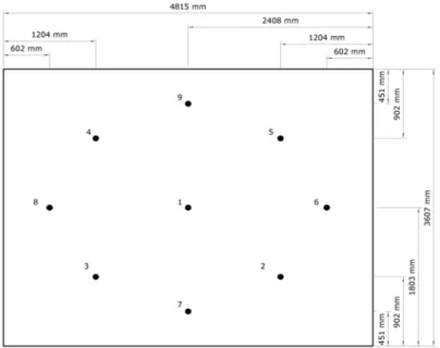
Figure 3-5 Location of displacement gauges on the unexposed side of the floor assembly... 12
Figure 3-6 Floor hydraulic loading system... 13
Figure 3-7 Load and deflection readings during floor assembly preloading period ... 14
Figure 3-8 Thermocouples installed on the unexposed side of the wall assembly... 14
Figure 3-9 Location of the unexposed side thermocouples on the wall assembly ... 15
Figure 3-10 Displacement gauges installed on the unexposed side of the wall assembly... 15
Figure 3-12 Wall loading system with loading beam and eight hydraulic loaders... 17
Figure 3-13 Load and deflection readings during wall assembly preloading period... 17
Figure 4-1 Average furnace temperature compared to the standard S101 fire curve... 18
Figure 4-2 Temperature of the floor assembly as a function of time ... 19
Figure 4-3 Loading and maximum deflection of the floor assembly as a function of time ... 20
Figure 4-4 Deflection of the full-scale floor assembly at the end of the testing period ... 20
Figure 4-5 Average differential pressure inside the furnace as a function of time ... 21
Figure 4-6 Exposed side of the floor assembly after testing showing the extent of charring and deflection ... 22
Figure 4-7 Deflection of the floor assembly after testing viewed from the unexposed and exposed sides, respectively... 22
Figure 4-8 Close-ups on cement board joints showing discoloration ... 22
Figure 4-9 Debris fallen from the floor assembly (distorted Z channels and furring strips) and close-up on the wood charring ... 23
Figure 4-10 Sections cut from the wall assembly after testing, viewed from the exposed side and cut side, respectively... 23
Figure 4-11 Average furnace temperature compared to the standard S101 fire curve... 24
Figure 4-12 Temperature of the unexposed side of the wall assembly as a function of time ... 24
Figure 4-14 Differential pressure inside the standard furnace as a function of time ... 26
Figure 4-15 Wall assembly after testing viewed from the exposed and unexposed side, respectively... 27
Figure 4-16 Close-up of failed the gypsum board on the unexposed side of the wall assembly after testing... 27
Figure 4-17 Wall assembly after testing showing the depth of charring on the exposed side... 27
Figure 4-18 Sections cut from the wall assembly after testing, viewed from the exposed and unexposed sides, respectively ... 28
Figure 4-19 Open joint between two CLT panels in the wall assembly after testing... 28
List of Tables
Table 4-1 Observations from standard fire test on full-scale floor assembly... 19Executive Summary
Standard fire endurance tests were performed on a full-scale floor assembly and a full-scale wall assembly constructed with cross-laminated timber (CLT) as the main structural element. The full-scale floor assembly consisted of CLT panels encapsulated with fiberglass wool and a single layer of 15.9 mm thick Type X gypsum board on the exposed side and with two layers of 12.7 mm thick cement board on the unexposed side. The full-scale wall assembly was constructed from CLT panels encapsulated with two layers of 15.9 mm thick Type X gypsum board on both faces. Nine thermocouples were installed on the unexposed face of both assemblies to monitor the temperature rise throughout the test and nine deflection gauges were installed on each assembly to monitor deformations. The superimposed load applied on the floor assembly was 9.4 kN/m² and the load imposed on the wall assembly was 449 kN/m. The fire endurance period of the full-scale floor assembly was 128 minutes and that of the full-scale wall assembly 219 minutes. Both the full-scale floor assembly and the full-scale wall assembly failed
structurally afterwards under the applied loading. No hose stream tests were carried out on the full-scale floor and wall assemblies.
Fire Endurance of Cross-Laminated Timber Floor and Wall Assemblies for Tall
Wood Buildings
Joseph Su, Audrey Roy-Poirier, Patrice Leroux, Pier-Simon Lafrance, Karl Gratton, Eric Gibbs and Robert Berzins
Chapter 1 Introduction
Cross-laminated timber (CLT) has been identified as a potential structural material for use in tall buildings. To support the use of CLT in tall wood buildings, fire endurance data is required for floor and wall assemblies. This report presents the results of standard fire endurance tests performed on a full-scale floor assembly and a full-full-scale wall assembly in accordance with CAN/ULC-S101-14 Standard
Method of Fire Endurance Tests of Building Construction and Materials. The floor and wall assemblies
were constructed by NRC and subjected to a standard fire endurance test inside NRC’s full-scale testing furnaces. Hose stream tests were not performed.
Chapter 2 Test specimens
2.1 Full-scale floor assembly
The floor assembly tested was constructed from CLT panels encapsulated with two layers of 12.7 mm thick cement board on the unexposed side (topside) and with fiberglass wool and a layer of 15.9 mm thick Type X gypsum board on the exposed side (underside). The floor measured 4815 mm (15ʹ-10ʺ) in length by 3607 mm (11ʹ-10ʺ) in width. Detailed construction drawings for the floor assembly can be found in Appendix A.
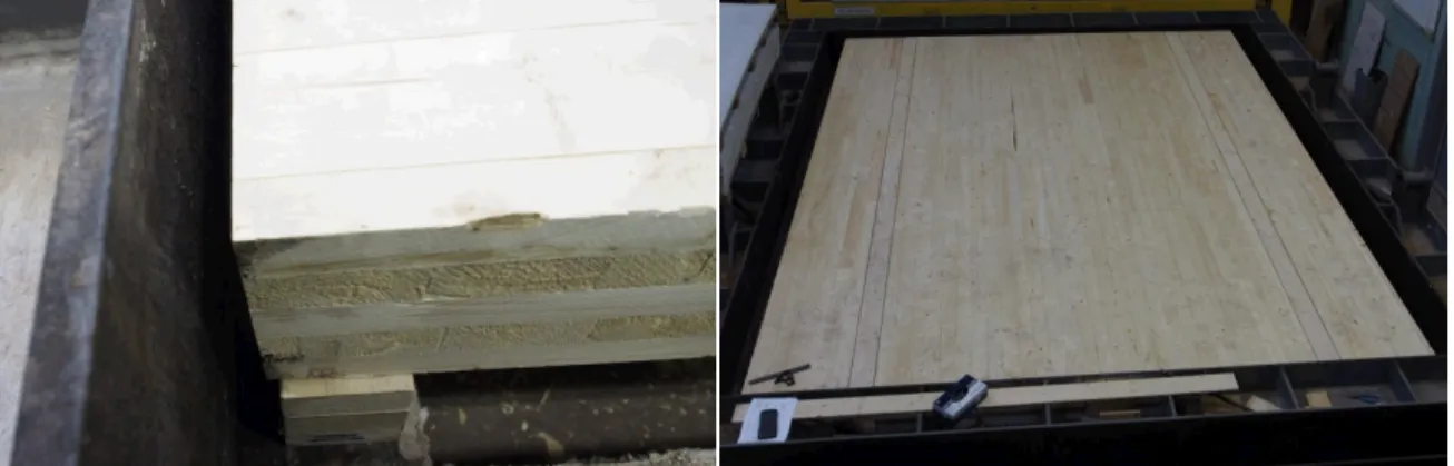
The main structural element of the floor assembly was constructed from three panels of 175 mm deep 5-ply CLT of grade E1 manufactured by Nordic. The moisture content of the CLT panels was measured with a Delmhorst BD-2100 moisture meter (serial no. 16 000) before testing. An average moisture content of 7.2% was obtained. The panels were aligned such that the grain of the outer layers of timber (on both the exposed and unexposed sides) ran along the length of the floor assembly. The CLT panels were joined on the unexposed side with strips of 12.7 mm thick plywood glued on each side with lines of 6 mm wide polyurethane construction adhesive and nailed on each side every 300 mm (starting at 150 mm from the edge of the assembly) with common 70 mm metal nails. Figure 2-1 shows the 5-ply CLT panels joined with strips of plywood on the unexposed side and Figure 2-2 shows the nails used to secure the strips of plywood to the unexposed side of the CLT panels.
Figure 2-1 CLT panels of 5-ply thickness joined with strips of plywood on the unexposed side
Figure 2-2 Strips of plywood joining the CLT panels on unexposed side with glue and nails installed
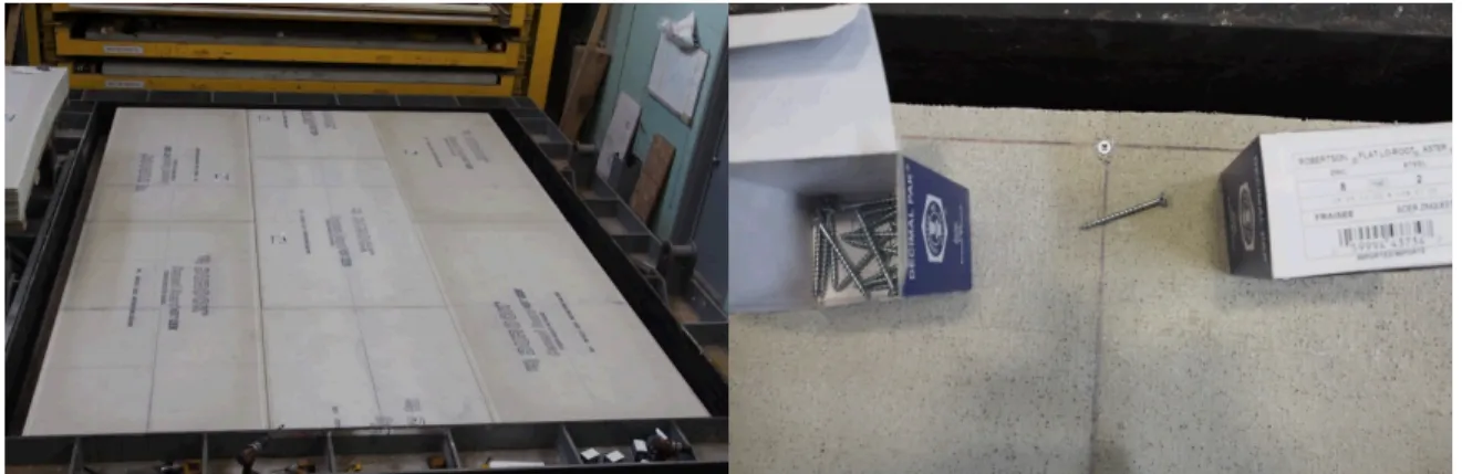
On the unexposed side, the CLT panels were covered with two staggered layers of 12.7 mm thick cement boards. The boards were manufactured from Portland cement, fly ash, expanded clay aggregate or expanded shale and a blend of proprietary mineral-based ingredients and fiber glass scrim. Expansion joints of a minimum of 3 mm (⅛ʺ) were created between the board sections. The cement boards were fastened to the CLT panels with 51 mm (2ʺ) long flat head zinc steel countersunk wood screws of size 8. Screws were spaced 610 mm apart starting 19 mm (¾ʺ) from the edge of the cement boards. Figure 2-3 shows the installation of the first layer of cement boards with screw placement and Figure 2-4 shows the installation of the second layer of cement boards with a close-up on the expansion joints.
Figure 2-3 First layer of cement boards on unexposed side and screw installation
Figure 2-4 Second layer of cement boards on unexposed side and close-up on expansion joints
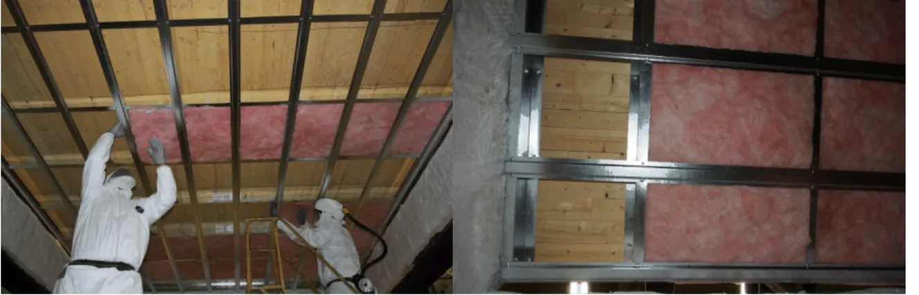
On the exposed side, 90 mm deep 26-gauge galvanized steel Z channels were installed to run along the width of the assembly at a spacing of 600 mm on centre. The Z channels were fastened to the CLT panels with 38 mm (1 ½ʺ) long flat head zinc steel wood screws of size 8. Screws were spaced at 300 mm on centre starting 150 mm from the ends of the channels. Figure 2-5 shows the Z channels installation.
Figure 2-5 Galvanized steel Z channels installed on exposed side (underside)
Running perpendicular to the Z channels, 16 mm (⅝ʺ) deep W14 furring strips made of 25-gauge galvanized steel were installed at 400 mm on centre. The furring strips were fastened to the Z channels
on each side of the furring strips. The space between the Z channels and behind the furring strips was filled with sections of 92 mm (3 ⅝ʺ) thick acoustic fiberglass wool with an R-value of 12. Figure 2-6 shows the furring strips installed against the Z channels and the completed fiberglass wool installation is shown in Figure 2-7.
Figure 2-6 W14 furring strips installed perpendicular to Z channels on exposed side and space behind furring being filled with fiberglass wool
Figure 2-7 Fiberglass wool inserted against the CLT panels between the Z channels on the exposed side
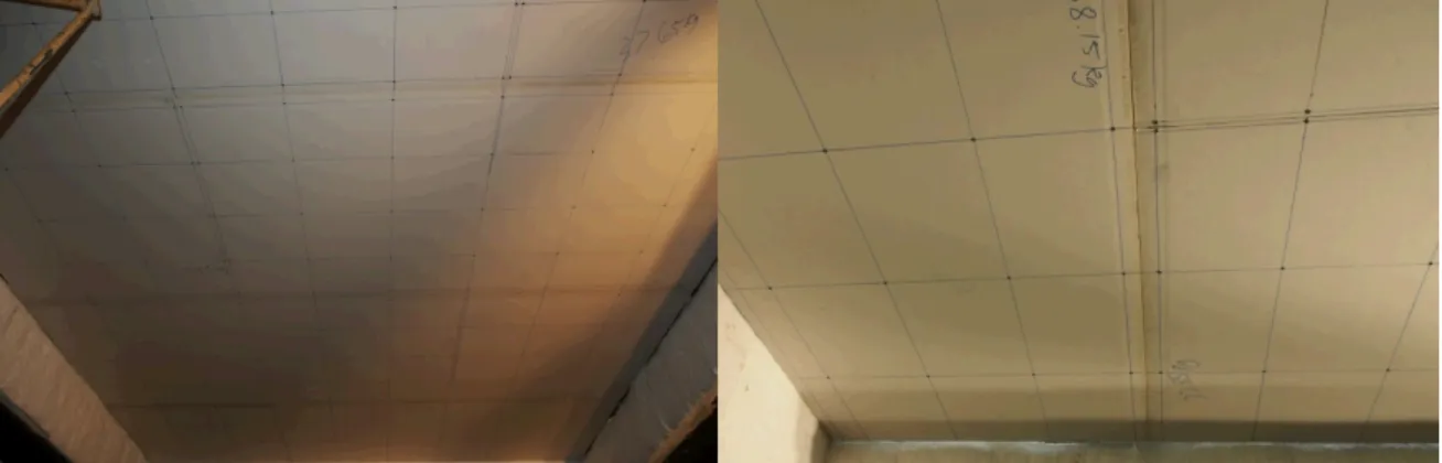
A single layer of 16 mm thick Type X gypsum board was installed onto the furring, covering the fiberglass wool. The gypsum boards were fixed with 32 mm (1 ¼ʺ) long type S screws spaced at 300 mm on centre starting at 150 mm from the edges of the assembly. Screws were placed at a minimum distance of 38 mm (1½ʺ) from the edges of all gypsum board sections. Joints between board sections were covered with tape and joint compound. All screw heads were also covered with joint compound. Figure 2-8 shows the installation of the gypsum boards and Figure 2-9 shows the joints and screw heads covered with tape and joint compound. Figure 2-10 shows the finished exposed side of the assembly installed inside the standard floor furnace.
Figure 2-8 Gypsum board layer installed on the exposed side and close-up on joints tape covering
Figure 2-9 Exposed face joints covered with tape and joint compound and screw heads covered with joint compound
Figure 2-10 Exposed side of the floor assembly placed onto the standard testing furnace
2.1.1 Mode of restraint
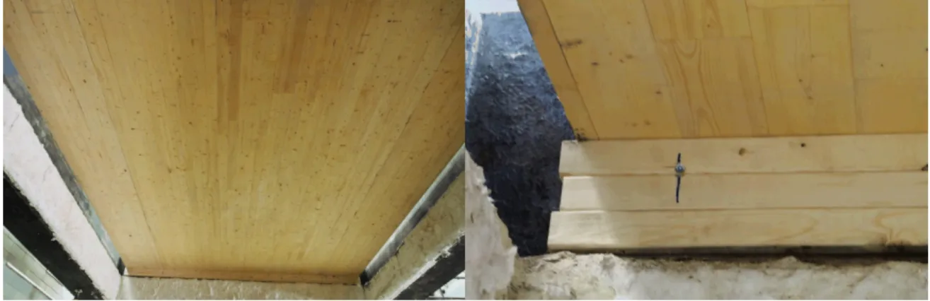
The floor assembly was unrestrained. The assembly was simply supported on the furnace frame at both extremities lengthwise. Three planks of 38 mm x 89 mm (2ʺx4ʺ) dimensional lumber were used on each end of the assembly to act as supports and lift the structural CLT panels such that the gypsum board on the exposed side of the assembly was aligned with the top of the furnace. The widthwise edges of the floor assembly remained unsupported. Figure 2-11 and Figure 2-12 show the assembly support from the exposed side and the unexposed side, respectively.
Figure 2-11 View of the floor assembly support from the exposed side (underside)
Figure 2-12 View of the floor assembly support from the unexposed side (topside)
2.2 Full-scale wall assembly
The wall assembly tested was constructed from cross-laminated timber (CLT) panels encapsulated with two layers of 16 mm thick Type X gypsum board on the unexposed side and two layers of 16 mm thick Type X gypsum board on the exposed side. The wall measured 3658 mm (12’-0’’) in width by 3048 mm (10’-0’’) in height. Detailed construction drawings for the wall assembly can be found in Appendix B. The main structural element of the wall assembly was constructed from three panels of 175 mm deep 5-ply cross-laminated timber of grade E1 manufactured by Nordic. The moisture content of the CLT panels was measured with a Delmhorst BD-2100 moisture meter (serial no. 16 000) before testing. An average moisture content of 7.2% was obtained. The panels were aligned such that the grain of the outer layers of wood (on both the exposed and unexposed sides) ran along the height of the wall. Holes were drilled into the CLT panels to facilitate installation into the wall furnace for testing. The holes were plugged with hardwood dowels glued with polyurethane construction adhesive and screwed in place from the unexposed side. Figure 2-13 shows the installation of the 5-ply CLT panels. The location of the holes drilled for manoeuvring purposes at the top of each panel section can be seen in Figure 2-13.
Figure 2-13 Installation of the central CLT panel into the wall frame and view of the three CLT panels from the unexposed side after installation, showing manoeuvring holes drilled at the top of each panel
The CLT panels were joined on the unexposed side with two strips of 12.7 mm thick plywood glued on each side with lines of 6 mm wide polyurethane construction adhesive and nailed on each side every 300 mm with common 70 mm metal nails (starting at 150 mm from the edges of the wall assembly). Figure 2-14 shows the glue and nails used to fasten strips of plywood to the CLT panels to join them on the unexposed side.
Figure 2-14 Plywood strips with glue lines and nails used to join the CLT panels on the unexposed side
On the unexposed side, two layers of 16 mm thick type X gypsum board were installed against the CLT panels in a staggered fashion. The gypsum boards were fixed with 51 mm (2ʺ) long type S screws spaced at 300 mm on centre starting at 150 mm (for the first or base layer) and 200 mm (for the second or face layer) from the edges of the assembly. Screws were placed at a minimum distance of 38 mm (1½ʺ) from the edges of all gypsum board sections. On the face layer only, joints between board sections were covered with tape and joint compound and all screw heads were covered with joint compound. Figure 2-15 shows the installation of the first layer of gypsum board on the unexposed side, Figure 2-16 shows the installation of the second layer of gypsum board in the unexposed side and Figure 2-17 shows the finished unexposed side of the assembly with joints covered with tape and joint compound and screw heads covered with joint compound.
Figure 2-15 First layer of gypsum board installed on the unexposed side of the assembly with a close-up on the joints between boards
Figure 2-16 Second layer of gypsum board installed on the unexposed side of the assembly with a close-up on the joints between boards
Figure 2-17 Unexposed face joints covered with tape and joint compound and screw heads covered with joint compound
The encapsulation materials are symmetrical on this wall assembly. As on the unexposed side, the exposed side of the assembly was covered with two staggered layers of 16 mm thick Type X gypsum board placed directly against the CLT panels. The gypsum boards were fixed with 51 mm (2ʺ) long type S screws spaced at 300 mm on centre starting at 150 mm (for the first or base layer) and 200 mm (for the second or face layer) from the edges of the assembly. Screws were placed at a minimum distance of 38 mm (1½ʺ) from the edges of all gypsum board sections. On the face layer only, joints between board
sections were covered with tape and joint compound and all screw heads were covered with joint compound. Figure 2-18 shows the installation of the first layer of gypsum board on the exposed side of the assembly, Figure 2-19 shows the installation of the second layer of gypsum board on the exposed side of the assembly and Figure 2-20 shows the finished exposed side of the assembly with joints covered with tape and joint compound and screw heads covered with joint compound.
Figure 2-18 First layer of gypsum board installed on the exposed side of the assembly with a close-up on the joints between boards
Figure 2-19 Second layer of gypsum board installed on the exposed side of the assembly
Chapter 3 Test procedure
Both assemblies were subjected to fire endurance tests following the requirements of CAN/ULC-S101-14. This section describes the instrumentation used in each test, as well as the loading applied to each assembly.
3.1 Standard floor test
3.1.1 Instrumentation
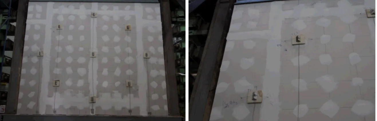
In accordance with the requirements of CAN/ULC-S101-14, a total of nine type K thermocouples were installed on the unexposed face of the floor assembly to monitor temperature rise throughout the test. The unexposed side thermocouples were held against the unexposed face of the assembly with felted refractory pads as described in CAN/ULC-S101-14. Small weights were used to maintain contact between the thermocouples and the unexposed surface of the assembly. Figure 3-1 shows the unexposed side thermocouples and their refractory pads. Figure 3-2 shows the location of the thermocouples on the unexposed side of the assembly.
Figure 3-2 Location of thermocouples on the unexposed side of the floor assembly (topside)
In addition, a total of nine type K thermocouples were installed on the exposed face of the CLT panels. These exposed thermocouples were stapled to the exposed surface of the CLT panels and were angled to ensure contact between the wood surface and the hot junction of the thermocouples. Figure 3-3 shows two of the thermocouples on the exposed side. The thermocouples on the exposed side of the CLT panels were installed in the same locations as the thermocouples on the unexposed side (see Figure 3-2).
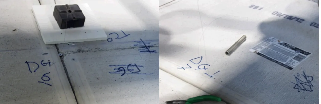
In accordance with CAN/ULC-S101-14, the deflection of the floor assembly was measured throughout the test duration. A total of nine linear position transducers were installed on the unexposed side of the floor assembly to monitor displacement. The displacement gauges used in the test have a precision of 0.1 mm within an accuracy of 0.4 mm. Figure 3-4 shows the wires connected to two displacement gauges and Figure 3-5 shows the location of the displacement gauges on the unexposed side of the assembly.
Figure 3-4 Displacement gauges installed on the unexposed side of the floor assembly
Figure 3-5 Location of displacement gauges on the unexposed side of the floor assembly
In accordance with CAN/ULC-S101-14, two differential pressure sensors were installed at the centre of the full-scale floor furnace to monitor the differential gas pressure throughout the test. The differential pressure sensor utilizes a variable capacitance pressure transducer combined with a glass-clad silicon chip, having an accuracy of 0.25% and a thermal coefficient of ±0.01%/°F. One pressure sensor was located at 0.46 m and the other was located at 2.29 m below the exposed specimen surface (the floor furnace is 2.74 m deep).
Two video cameras were used to record the behaviour of the exposed side of the floor assembly as viewed through two ports (east and west sides) in the standard fire furnace. A third video camera recorded the behaviour of the unexposed side of the floor assembly.
3.1.2 Loading
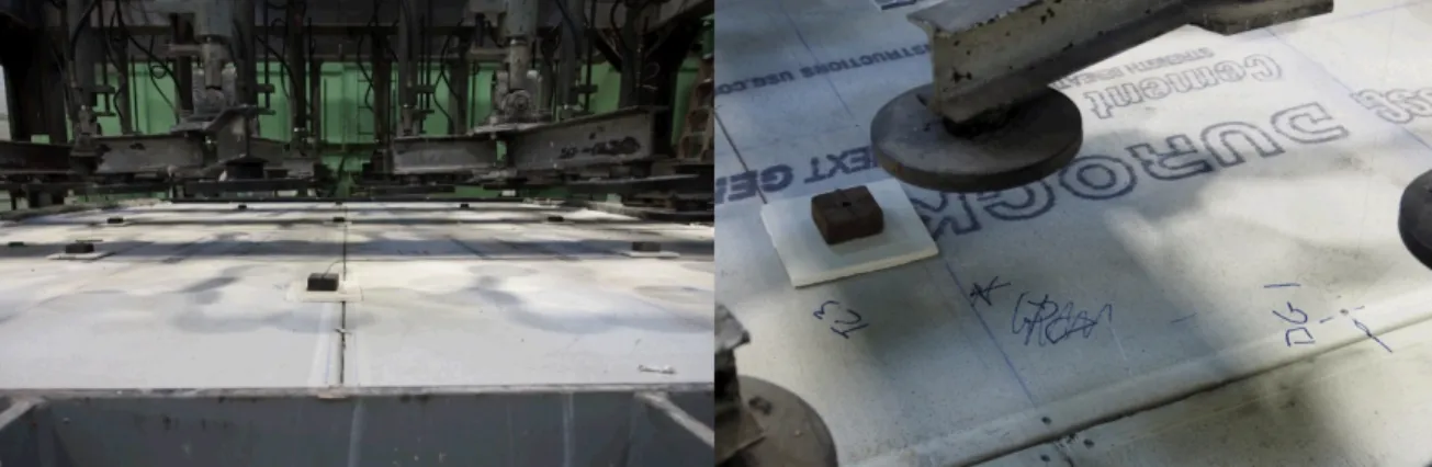
A superimposed load of 9.4 kN/m² was specified by the client for this test. Loading was applied to the floor assembly through a system of 30 hydraulic cylinders each distributing its load over a set of three loading pads. Figure 3-6 shows the system of hydraulic cylinders used to apply the superimposed floor load.
Figure 3-6 Floor hydraulic loading system
The floor assembly was preloaded on 5 November 2014 starting at 11:42:50. The total superimposed load was reached at 12:42:20. In accordance with CAN/ULC-S101-14, preloading was applied in four increments of 25% of the total load and deflections were allowed to stabilise between each preload increment. Figure 3-7 shows the load applied to the floor assembly and the deflections measured throughout the floor over the preload period.
Figure 3-7 Load and deflection readings during floor assembly preloading period
3.2 Standard wall test
3.2.1 Instrumentation
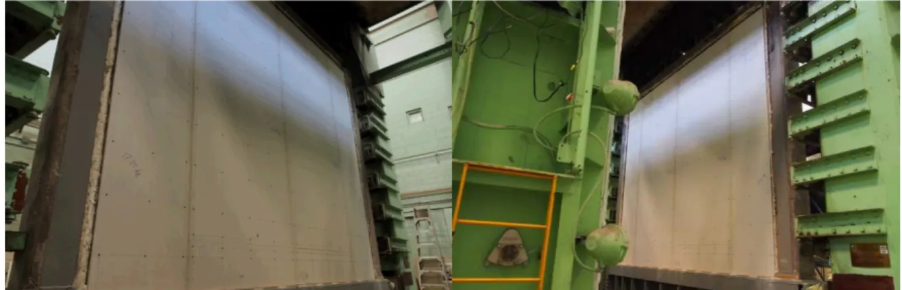
In accordance with the requirements of CAN/ULC-S101-14, a total of nine type K thermocouples were installed on the unexposed face of the wall assembly to monitor temperature rise throughout the test. The unexposed side thermocouples were held against the unexposed face of the assembly with felted refractory pads as described in CAN/ULC-S101-14. A tensioned wire was used to hold the thermocouples and refractory pads in contact with the unexposed wall surface. Figure 3-8 shows the unexposed side thermocouples and their refractory pads. The location of the thermocouples installed on the unexposed side of the wall assembly is depicted in Figure 3-9.
Figure 3-8 Thermocouples installed on the unexposed side of the wall assembly 0 1 2 3 4 5 6 7 8 9 10 -2 0 2 4 6 8 10 0 5 10 15 20 25 30 35 40 45 50 55 60 Lo ad (k N /m ²) D is pl ac em en t ( cm )
Elapsed time (min)
DFL-01 DFL-02
DFL-03 DFL-04
DFL-05 DFL-06
DFL-07 DFL-08
Figure 3-9 Location of the unexposed side thermocouples on the wall assembly
In accordance with CAN/ULC-S101-14, the deflection of the wall assembly was monitored throughout the test duration. A total of nine linear position transducers were installed on the unexposed side of the wall assembly to monitor displacements. The displacement gauges used in the test have a precision of 0.1 mm within an accuracy of 0.4 mm. Figure 3-10 shows two displacement gauges installed on the unexposed side of the assembly and Figure 3-11 shows the location of the displacement gauges.
Figure 3-11 Location of displacement gauges on the unexposed side of the wall assembly
In accordance with CAN/ULC-S101-14, two differential pressure sensors were installed inside the full-scale wall furnace to monitor the differential gas pressure throughout the test. The differential pressure sensor utilizes a variable capacitance pressure transducer combined with a glass-clad silicon chip, having an accuracy of 0.25% and a thermal coefficient of ±0.01%/°F. One pressure sensor was located at 0.46 m and the other was located at 2.59 m from the top of the wall specimen (the wall specimen is 3.048 m high).
Two video cameras were used to record the behaviour of the exposed side of the wall assembly as viewed through two ports (east and west sides) in the standard fire furnace. A third video camera recorded the behaviour of the unexposed side of the wall assembly.
3.2.2 Loading
A total superimposed load of 449 kN/m was applied to the wall assembly as specified by the client. Loading was applied to the wall from the top using eight hydraulic loaders. A steel beam was used to distribute the load evenly over the width of the wall. Figure 3-12 shows the wall loading system.
Figure 3-12 Wall loading system with loading beam and eight hydraulic loaders
The wall assembly was preloaded on 6 November 2014 starting at 9:58:53. The total superimposed load was reached at 10:59:13. In accordance with CAN/ULC-S101-14, preloading was applied in four
increments of 25% of the total load and deflections were allowed to stabilise between each preload increment. Figure 3-13 shows the wall loading and deflections during the preload period.
Figure 3-13 Load and deflection readings during wall assembly preloading period
Chapter 4 Test results
This section presents the data collected during the two standard fire endurance tests. Information is reported according to the requirements of the CAN/ULC-S101-14 standard.
4.1 Full-scale standard floor test
A full-scale standard fire endurance test was performed on the floor assembly described in Section 2.1 on 5 November 2014, beginning at 13:16:37. The test was terminated after 2:08:25 (128.42 min) of elapsed test time.
0 100 200 300 400 500 -1.2 -1.0 -0.8 -0.6 -0.4 -0.2 0.0 0 10 20 30 40 50 60 70 80 90 100 Lo ad (k N /m ) D is pl ac em en t ( cm )
Elapsed time (min)
DFL-01 DFL-02
DFL-03 DFL-04
DFL-05 DFL-06
DFL-07 DFL-08
4.1.1 Temperatures
Over the duration of the test, the temperature of the furnace was measured using nine thermocouples evenly distributed inside the furnace, as required by CAN/ULC-S101-14. Figure 4-1 compares the average furnace temperature as a function of time to the standard time-temperature curve for control of fire tests defined by CAN/ULC-S101-14. Accurate furnace control was achieved over the entire duration of the test. The area under the average furnace temperature curve falls within 0.1% of the area of the S101 standard time-temperature curve, meeting the 5% requirement established by the standard.
Figure 4-1 Average furnace temperature compared to the standard S101 fire curve
As described in Section 3.1.1, thermocouples were installed in two planes in the floor assembly: on the surface of the CLT panels on the exposed side and on the unexposed side of the floor assembly. Figure 4-2 shows the temperature of the floor assembly as a function of test time. Both the average temperature of the exposed wood surface and the maximum temperature of the unexposed assembly face are plotted, along with the average furnace temperature for reference. The maximum temperature of the unexposed face of the floor assembly did not exceed 27°C throughout the test duration.
0 100 200 300 400 500 600 700 800 900 1000 1100 0 10 20 30 40 50 60 70 80 90 100 110 120 130 Te m pe ra tu re (° C)
Elapsed time (min)
S101 standard time-temperature curve Average furnace temperature
Figure 4-2 Temperature of the floor assembly as a function of time
4.1.2 Observations
Table 4-1 reports observations of the behaviour and condition of the floor assembly over the duration of the experiment. Observations were based on video recordings of the test (see Section 3.1.1 for a
description of the test instrumentation).
Table 4-1 Observations from standard fire test on full-scale floor assembly Elapsed time Observation
0:00:42 Paper on surface of exposed gypsum board starting to darken
0:01:17 Screw heads becoming visible through joint compound on exposed gypsum boards 0:02:37 Joint compound on surface of exposed gypsum boards drying off
0:02:40 Piece of tape falling off a gypsum board joint on exposed side 0:02:55 Tape falling off several gypsum board joints on exposed side 0:04:20 Several pieces of joint tape flaming on exposed side
0:07:42 Joint compound falling off heads of screws and gypsum board joints on exposed side 0:15:56 Almost all joint compound has fallen off gypsum boards on exposed side
0:16:40 Flaming visible through joints between gypsum boards on exposed side 0:18:42 Large flames visible through most gypsum board joints on exposed side 0:25:22 Joints between gypsum boards visibly opening up on exposed side 0:26:46 Corner of one gypsum board section drooping on exposed side 0:28:09 Large flames behind drooping gypsum board on exposed side 0:32:00 Several gypsum board joints bowing visibly on exposed side 0:33:33 Fall-off of first gypsum board piece on exposed side
0:33:35 Sections of fiberglass wool falling off behind missing gypsum board on exposed side 0:42:25 Furring strips visibly distorted on exposed side
0:42:50 Fall-off of large sections of gypsum board on exposed side 0:42:51 Drooping of fiberglass wool on exposed side
0:46:02 Entire assembly exposed face engulfed in flames 1:16:45 Fall-off of first piece of wood char on exposed side
1:24:11 Furring and Z channel assembly dropping down on exposed side 1:24:14 Large pieces of wood char falling off from exposed side 1:28:09 Fall-off of large piece of wood char from exposed side 1:43:20 Surface of second ply of CLT visible from exposed side
1:55:52 Fall-off of large piece of wood char from second ply of CLT on exposed side 0 100 200 300 400 500 600 700 800 900 1000 1100 0 10 20 30 40 50 60 70 80 90 100 110 120 130 Te m pe ra tu re (° C)
Elapsed time (min)
Average furnace temperature Maximum unexposed face temperature Average exposed wood surface temperature
2:01:18 Fall-off of several small pieces of wood char from second ply of CLT on exposed side 2:07:34 Loud cracking sound heard from floor assembly deflection
2:07:41 Heavy smoke visible around perimeter of floor assembly on unexposed side 2:07:47 Floor assembly deflection visible from unexposed side
2:07:55 Floor assembly deflection accelerating 2:08:24 Floor structural failure
4.1.3 Deflection
Figure 4-3 shows the load applied to the floor assembly and the maximum deflection of the floor over the duration of the experiment. The measurements have a precision accuracy of better than 1 mm. Large deflections began to occur after 112 min of testing. The floor assembly sustained the applied load of 9.4 kN/m² until 2:07:36 (127.6 min) of testing had elapsed. At this point, the floor began deflecting rapidly and the load carried by the floor quickly dropped. Figure 4-4 shows the deflection of the floor at the end of the test period.
Figure 4-3 Loading and maximum deflection of the floor assembly as a function of time
Figure 4-4 Deflection of the full-scale floor assembly at the end of the testing period 0 1 2 3 4 5 6 7 8 9 10 -40 -35 -30 -25 -20 -15 -10 -5 0 0 10 20 30 40 50 60 70 80 90 100 110 120 130 Lo ad (k N /m ²) D ef le ct io n (c m )
Elapsed Time (min)
Maximum deflection Load
4.1.4 Differential pressure
Figure 4-5 shows the differential pressure inside the standard fire test furnace as a function of elapsed test time. The measurements have a precision accuracy of better than 0.1 Pa. Beyond the first 10 min of the test, the differential pressure is within the range of −10 Pa to +12 Pa.
Figure 4-5 Average differential pressure inside the furnace as a function of time
4.1.5 Failure
According to CAN/ULC-S101-14, the fire endurance period of an unrestrained floor assembly is defined by the period over which: the floor sustained the applied load without passage of flames or gases hot enough to ignite cotton pads; the average temperature measured on the unexposed side of the floor assembly did not exceed 140°C above the initial average temperature of the unexposed side; and no individual temperature measured on the unexposed side of the floor assembly exceeded 180°C above the initial temperature.
The full-scale floor assembly failed structurally as a result of excessive deflection and inability to carry the superimposed load after 128 min of testing. At this time, the temperatures on the unexposed side of the floor assembly remained below the failure criteria defined in CAN/ULC-S101-14 (see Figure 4-2). Figure 4-6 to Figure 4-10 show the condition of the floor assembly after testing. The deflection of the floor is evident in Figure 4-6 and Figure 4-7. Figure 4-8 shows the condition of the unexposed cement board joints at the end of the test and Figure 4-9 shows the debris from the exposed side and a close-up on charring of the exposed wood. Figure 4-10 shows sections cut from the floor assembly exposing the depth of charring. The maximum depth of charring is 2.5 plies out of the 5-ply CLT panels.
-15 -10 -5 0 5 10 15 10 20 30 40 50 60 70 80 90 100 110 120 130 D iff er en tia l p re ss ur e (P a)
Elapsed time (min)
Figure 4-6 Exposed side of the floor assembly after testing showing the extent of charring and deflection
Figure 4-7 Deflection of the floor assembly after testing viewed from the unexposed and exposed sides, respectively
Figure 4-9 Debris fallen from the floor assembly (distorted Z channels and furring strips) and close-up on the wood charring
Figure 4-10 Sections cut from the wall assembly after testing, viewed from the exposed side and cut side, respectively
4.2 Full-scale standard wall test
A full-scale standard fire endurance test was performed on the wall assembly described in Section 2.2 on 6 November 2014, beginning at 11:35:19. The test was terminated after 3:39:20 (219.33 min) of elapsed test time.
4.2.1 Temperatures
Over the duration of the test, the temperature of the furnace was measured using nine thermocouples evenly distributed inside the furnace, as required by CAN/ULC-S101-14. Figure 4-11 compares the average furnace temperature as a function of time to the standard time-temperature curve for control of fire tests defined by CAN/ULC-S101-14. Accurate furnace control was achieved over the entire
duration of the test. The area under the average furnace temperature curve falls within 0.1% of the area of the S101 standard time-temperature curve, meeting the 5% requirement established by the standard.
Figure 4-11 Average furnace temperature compared to the standard S101 fire curve
As described in Section 3.2.1, nine thermocouples were installed on the unexposed face of the wall assembly. Figure 4-12 shows the maximum temperature measured on the unexposed side of the wall assembly as a function of test time, along with the average furnace temperature plotted as reference. The maximum temperature of the unexposed face of the wall assembly did not exceed 22°C throughout the test duration.
Figure 4-12 Temperature of the unexposed side of the wall assembly as a function of time
4.2.2 Observations
Table 4-2 reports observations of the behaviour and condition of the wall assembly over the duration of the experiment. Observations were based on video recordings of the test (see Section 3.2.1 for a description of the test instrumentation).
0 100 200 300 400 500 600 700 800 900 1000 1100 0 30 60 90 120 150 180 210 240 Te m pe ra tu re (° C)
Elapsed time (min)
S101 standard time-temperature curve Average furnace temperature
0 100 200 300 400 500 600 700 800 900 1000 1100 0 30 60 90 120 150 180 210 240 Te m pe ra tu re (° C)
Elapsed time (min)
Average furnace temperature Maximum unexposed face temperature
Table 4-2 Observations from standard fire test of full-scale wall assembly Elapsed time Observation
0:00:54 Location of screw heads visible through joint compound on exposed side 0:02:01 Section of joint tape in flame on exposed side
0:04:49 Joint compound flaking off
0:09:22 All screw heads visible, joint compound remains on some gypsum board joints on exposed side 0:13:24 All joint compound fallen off
1:05:24 Flames visible inside a gypsum board joint on exposed side 1:21:46 Gypsum board joints distorting on exposed side
1:24:44 Gypsum board joints visibly widening on exposed side 1:51:01 Fall-off of face layer gypsum board piece on exposed side 1:56:45 Fall-off of face layer gypsum board piece on exposed side
2:02:21 Face layer of gypsum board peeling off and exposing second layer on exposed side 2:05:05 All joints between gypsum boards in flame on exposed side
2:16:17 Second layer of gypsum board cracking and visibly drying on exposed side 2:42:33 Section of second layer gypsum board falling off on exposed side
2:54:14 Large section of gypsum board and attached wood char layer falling off on exposed side 2:54:19 Heavy flames engulfing assembly on exposed side
3:02:33 All gypsum board has fallen off on exposed side
3:39:17 Joint between exposed face gypsum boards opening up quickly????? 3:39:18 Wall movement visible on exposed side
3:39:21 Wall structural failure
4.2.3 Deflection
Figure 4-13 shows the load applied to the wall assembly and the maximum deflection of the wall over the duration of the experiment. The measurements have a precision accuracy of better than 1 mm. Deflections began to accelerate after 184 min of testing. The wall assembly sustained the applied load of 449 kN/m until 219 min of testing had elapsed. At this point, the wall deflected rapidly and the load carried by the wall dropped severely.
Figure 4-13 Loading and maximum deflection of the wall assembly as a function of time 0 50 100 150 200 250 300 350 400 450 500 -14 -12 -10 -8 -6 -4 -2 0 0 30 60 90 120 150 180 210 240 Lo ad (k N /m ) D ef le ct io n (c m )
Elapsed time (min)
Maximum deflection Load
4.2.4 Differential pressure
Figure 4-14 shows the differential air pressure measured at two heights inside the standard fire test furnace as a function of elapsed test time. The bottom pressure transducer is located 457 mm (1.5’) from the bottom of the wall and the top pressure transducer is located 2591 mm (8.5’) from the bottom of the wall. The measurements have a precision accuracy of better than 0.1 Pa. Beyond the first 10 min of the test, the differential pressure measured by the bottom transducer is within the range of −18 Pa to −10 Pa and the differential pressure at the top transducer is between −1 Pa and 6 Pa. Based on linear interpolation between the differential pressure measured at each transducer, the neutral plane was located at an average height of 2256 mm above the bottom of the wall over the duration of the test.
Figure 4-14 Differential pressure inside the standard furnace as a function of time
4.2.5 Failure
According to CAN/ULC-S101-14, the fire endurance period of a loadbearing wall assembly is defined by the period over which: the floor sustained the applied load without passage of flames or gases hot enough to ignite cotton pads; the average temperature measured on the unexposed side of the floor assembly did not exceed 140°C above the initial average temperature of the unexposed side; and no individual temperature measured on the unexposed side of the floor assembly exceeded 180°C above the initial temperature.
The full-scale wall assembly failed structurally as a result of excessive deflection and inability to carry the superimposed load after 219 min of testing. At this time, the temperatures on the unexposed side of the floor assembly remained below the failure criteria defined in CAN/ULC-S101-14. However, as the wall buckled, flaming appeared on the unexposed side of the assembly. Figure 4-15 to Figure 4-19 show the condition of the floor assembly after testing. The average depth of charring is 2.5 plies out of the 5-ply CLT panels. In some areas, charring is as deep as 3 plies.
-30 -20 -10 0 10 20 30 0 30 60 90 120 150 180 210 240 D iff er en tia l p re ss ur e (P a)
Elapsed time (min)
Bottom pressure transducer Top pressure transducer
Figure 4-15 Wall assembly after testing viewed from the exposed and unexposed side, respectively
Figure 4-16 Close-up of failed the gypsum board on the unexposed side of the wall assembly after testing
Figure 4-18 Sections cut from the wall assembly after testing, viewed from the exposed and unexposed sides, respectively
Figure 4-19 Open joint between two CLT panels in the wall assembly after testing
Chapter 5 Fire endurance period
5.1 Full-scale floor assembly
The fire endurance period of the full-scale floor assembly described in Section 2.1 was 128 minutes. Assembly failure occurred as a result of a loss of load-carrying capacity. A hose stream test was not performed on the full-scale floor assembly.
5.2 Full-scale wall assembly
The fire endurance period of the full-scale wall assembly described in Section 2.2 was 219 minutes. Assembly failure occurred as a result of a loss of load carrying capacity. A hose stream test was not carried out on the full-scale floor assembly.
Acknowledgments
Financial support provided by Natural Resources Canada and extensive technical input by Nordic are gratefully acknowledged.
References
ULC Standards (2014). CAN/ULC-S101-14: Standard Methods of Fire Endurance Tests of Building Construction and Materials. National Standard of Canada.
Appendix A – Full-scale floor assembly drawings
STEP 1: CLT UNEXPOSED SIDE
PLYWOOD STRIP 12.7mm Glued with a line of 6mm of PL Premium adhesive on each side of the panel and nailed with common nails of 70mm @ 300mm o.c., on each panel
1stnail at 150mm from edge
PLYWOOD STRIP 12.7mm
Glued with a line of 6mm of PL Premium adhesive on each side of the panel and nailed with common nails of 70mm @ 300mm o.c., on each panel
1stnail at 150mm from edge
5-PLY CLT 175mm (GRADE E1) 5-PLY CLT 175mm (GRADE E1) 5-PLY CLT 175mm (GRADE E1)
STEP 2: CEMENT BOARD 1
NOTES:
-LEAVE AN EXPANSION JOINT BETWEEN BOARDS OF A MINIMUM OF 3 mm (1/8ʺ) -DRILL HOLES OF 1.6 mm (1/16ʺ) LARGER THAN THE DIAMETER OF THE INSTALLATION SCREW
CEMENT BOARD 12.7mm Fixed with 51 mm (2ʺ) wood screws @ 610 mm (24ʺ) o.c. at 19 mm (3/4ʺ) from the edge of the board
STEP 3: CEMENT BOARD 2
CEMENT BOARD 12.7mm Staggered with other layer (step 2) Fixed with 51 mm (2ʺ) wood screws @ 610 mm (24ʺ o.c. at 19 mm (3/4ʺ) from the edge of the board
NOTES:
-LEAVE AN EXPANSION JOINT BETWEEN BOARDS OF A MINIMUM OF 3 mm (1/8ʺ) -DRILL HOLES OF 1.6 mm (1/16ʺ) LARGER THAN THE DIAMETER OF THE INSTALLATION SCREW
STEP 4: Z CHANNEL + FIBERGLASS WOOL EXPOSED SIDE
NOTE THE CHANGE OF SIDE
Z CHANNEL 90 @ 600mm o.c. Fixed with wood screws 38 mm (1-1/2ʺ) #8 @300mm o.c.
1stscrew at 150mm from edge
QUIETZONE ECOTOUCH PINK WOOL 90mm
Z CHANNEL IN 26-GAUGE GALVANIZED STEEL
Vis métallique auto-torouseuse à tête cylindrique à dépouille #6x1ʺ
STEP 5: OMEGA FURRING (W14)
OMEGA FURRING (W14) 16mm @ 400mm o.c. Fixed with pan head metal screw 25 mm (6x1") @600mm o.c. on each side of the furring
FURRING OMEGA (W14) 25-GAUGE METAL
STEP 6: 16 mm TYPE X GYPSUM BOARD
GYPSUM BOARD 16mm TYPE X FIXED WITH SCREWS
Type S 32 mm (1-1/4ʺ) @300mm o.c. 1stscrew at 150mm from edge
Gypsum board joints must be covered with tape and joint compound.
Appendix B – Full-scale wall assembly drawings
STEP 1: CLT UNEXPOSED SIDE
PLYWOOD STRIP 12.7mm Glued with a line of 6mm of PL Premium adhesive on each side of the panel and nailed with common nails of 70mm @ 300mm o.c. on each panel
1stnail at 150mm from edge
PLYWOOD STRIP 12.7mm Glued with a line of 6mm of PL Premium adhesive on each side of the panel and nailed with common nails of 70mm @ 300mm o.c. on each panel
1stnail at 150mm from edge
5-PLY CLT 175mm (GRADE E1)
5-PLY CLT 175mm (GRADE E1)
STEP 2: GYPSUM BOARD 1 UNEXPOSED SIDE
GYPSUM BOARD 16mm FIXED WITH SCREW Type S 51 mm (2ʺ) @300mm o.c. The minimum edge distance is 38mm 1stscrew at 150mm from edge
STEP 3: GYPSUM BOARD 2 UNEXPOSED SIDE
GYPSUM BOARD 16mm FIXED WITH SCREW Type S 51 mm (2ʺ) @300mm o.c. 1stscrew at 200mm from edge
The joints between boards must be covered with tape and joint compound
STEP 4: GYPSUM BOARD 3 EXPOSED SIDE
NOTE THE CHANGE OF SIDE
GYPSUM BOARD 16mm FIXED WITH SCREW Type S 51 mm (2ʺ) @300mm o.c. The minimum edge distance is 38mm 1stscrew at 150mm from edge
STEP 5: GYPSUM BOARD 4 EXPOSED SIDE
GYPSUM BOARD 16mm FIXED WITH SCREW Type S 51 mm (2ʺ) @300mm o.c. 1stscrew at 200mm from edge
The joints between boards must be covered with tape and joint compound