Publisher’s version / Version de l'éditeur:
Vous avez des questions? Nous pouvons vous aider. Pour communiquer directement avec un auteur, consultez la
première page de la revue dans laquelle son article a été publié afin de trouver ses coordonnées. Si vous n’arrivez pas à les repérer, communiquez avec nous à PublicationsArchive-ArchivesPublications@nrc-cnrc.gc.ca.
Questions? Contact the NRC Publications Archive team at
PublicationsArchive-ArchivesPublications@nrc-cnrc.gc.ca. If you wish to email the authors directly, please see the first page of the publication for their contact information.
https://publications-cnrc.canada.ca/fra/droits
L’accès à ce site Web et l’utilisation de son contenu sont assujettis aux conditions présentées dans le site LISEZ CES CONDITIONS ATTENTIVEMENT AVANT D’UTILISER CE SITE WEB.
Surface & Coatings Technology, 337, pp. 53-62, 2017-12-29
READ THESE TERMS AND CONDITIONS CAREFULLY BEFORE USING THIS WEBSITE.
https://nrc-publications.canada.ca/eng/copyright
NRC Publications Archive Record / Notice des Archives des publications du CNRC :
https://nrc-publications.canada.ca/eng/view/object/?id=3ca741d4-b36a-4973-a6dc-9de1e6f8077d https://publications-cnrc.canada.ca/fra/voir/objet/?id=3ca741d4-b36a-4973-a6dc-9de1e6f8077d
NRC Publications Archive
Archives des publications du CNRC
This publication could be one of several versions: author’s original, accepted manuscript or the publisher’s version. / La version de cette publication peut être l’une des suivantes : la version prépublication de l’auteur, la version acceptée du manuscrit ou la version de l’éditeur.
For the publisher’s version, please access the DOI link below./ Pour consulter la version de l’éditeur, utilisez le lien DOI ci-dessous.
https://doi.org/10.1016/j.surfcoat.2017.12.063
Access and use of this website and the material on it are subject to the Terms and Conditions set forth at
Investigation of the feedstock deposition behavior in a cold sprayed 316L/Fe composite coating
Chu, Xin; Chakrabarty, Rohan; Che, Hanqing; Shang, Lihong; Vo, Phuong; Song, Jun; Yue, Stephen
1
Investigation of the Feedstock Deposition Behavior in a Cold Sprayed 316L/Fe
Composite Coating
Xin Chu a *, Rohan Chakrabarty a, Hanqing Che a, Lihong Shang a, Phuong Vo b, Jun Song a, and
Stephen Yue a
a. Department of Mining and Materials Engineering, McGill University, Montreal, Quebec H3A 0C5, Canada b. National Research Council Canada, Boucherville, Quebec J4B 6Y4, Canada
*Corresponding author: Xin Chu
Email: xin.chu@mail.mcgill.ca
Tel: +1 438.388.0632
2
Abstract:
Mixing powders in cold spray is a straightforward method to produce composite coatings,
but a direct interpretation of the mixed powder deposition behavior from coating microstructure
is often difficult. In this study, to investigate the feedstock deposition behavior in a cold sprayed
316L-10 wt.% Fe (10Fe) metal-metal composite coating, splats deposited onto the as-polished
316L and Fe coatings with four types of impact scenarios were studied: (i) 316L on 316L, (ii)
316L on Fe, (iii) Fe on 316L, and (iv) Fe on Fe. The splat flattening ratio and coating crater
depth/diameter were measured using a light optical microscope (LOM) and an optical
profilometer to evaluate the degrees of particle and coating deformation. Finite element (FE)
simulations were performed to obtain the splat rebound behavior during impact. A modified ball
bond shear test was performed to determine the adhesion strength/energy of the cold spray splats.
Results reveal distinct interparticle bonding features in the 10Fe coating, especially at the mixed
316L/Fe interfaces where a preferential location of inter-lamellar cracks can be seen. Similar
bonding features were also observed in the deposited splats, indicating the splat on coating tests
to be indicative of the coating build-up process. Finally, the feedstock deposition behavior in the
10Fe coating was explained through splat characterizations and FE simulations from hardness,
surface oxide layer and particle morphology.
3
1. Introduction
Cold spray can be an effective alternative to fabricate metal matrix composites (MMC)
due to its low process temperature which minimizes the oxidation and chemical degradation of
the feedstock. Some typical examples extensively studied by researchers are metal-ceramic
composites, e.g. WC-based [1-6] and Al2O3-based [7-11]. Cold spray utilizes the plastic
deformability of the metal thus the brittle ceramic can be deposited. Compared with
metal-ceramic composites, however, relatively few studies of cold spraying metal-metal composites are
reported, in particular, concerning the feedstock deposition behavior [12-14].
Among the various strategies to obtain composite coatings in cold spray, e.g. coating or
mechanically milling the powders, mixing powders (pre-blending and dual feeding) is a
straightforward approach [15, 16]. This method enables free interactions between the mixed
components during flight and upon impact, which can lead to an improved cold sprayability of
the component powder, e.g. reduced porosity and increased deposition efficiency (DE) [13,
17-21]. Whereas unlike metal-ceramic mixtures, where the impinging ceramic powders only
contribute to tamping and roughening of the surface layers [20], almost all metal powders can
exhibit certain degrees of cold sprayabilities and this generates uncertainties of the feedstock
deposition behavior at mixed metal-metal interfaces. Thus, it is often difficult to prescribe the
suitable process parameters for a specific metal-metal mixture in cold spray.
The coating formation process in cold spray incorporates, but is not limited to, the
individual deposition behavior of a single particle [22]. Other factors such as characteristics of
the previously deposited layers and the successive peening/erosion of the subsequent particles
can all affect the individual particle deposition [22]. Individual particle impact tests (or splat tests)
can be considered as a monolayer coating deposition and is often used to study the coating
4
suitable trial-and-error approach to explore the cold spray feasibility or to identify the optimal
process parameters of specific particle/substrate combinations. As effects of successive tamping
and surface roughness are avoided by performing splat tests, the individual behavior of a
feedstock during deposition can be clearly observed, e.g. particle deformation, rebound, and
jetting. Moreover, the splat behavior can often be indicative of several coating cold sprayability
metrics (e.g. adhesion [24] and DE [25]) in the case of the similar particle and substrate material.
Splat tests are usually generated by low feed rate spraying of single particles onto an
as-polished substrate. In a previous work [26], single component 316L, Fe, and composite 316L/Fe
coatings were cold sprayed deposited and splat tests were performed onto the as-polished
coatings. It was observed that the partial DE of the feedstock components in composite coatings
can be indicated by the respective splat bond ratio in splat tests. This motivates us to study the
single splats in order to investigate the feedstock deposition behavior in the composite coating,
since a direct interpretation of it from coating microstructure is difficult. In this study, the
feedstock deposition behavior in a 10Fe composite coating was mainly investigated. The
interparticle bonding features in the cold sprayed coatings and deposited splats were discussed
and compared. Experimental characterizations and finite element (FE) simulations of the splats
5
2. Materials and Methods
2.1 Experiments
Commercially available 316L stainless steel powder (Sandvik Osprey, Neath-Port Talbot,
UK) and commercial purity Fe powder (Quebec Metal Powders, Sorel-Tracy, Canada) were used
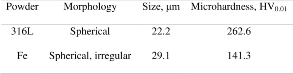
as the feedstock. SEM images of the feedstock are shown in Fig. 1 and characteristics of the
feedstock are presented in Table 1. The average particle size was determined using a Horiba
LA-920 laser diffraction analyzer (Horiba, Tokyo, Japan). The average Vickers hardness of the
feedstock was measured using a Clark CM-100AT Microhardness Tester (Sun-Tec, Novi, USA)
for a penetration time of 15 s under 10 g load.
Spraying was performed at the McGill-NRC cold spray facility, located at the National
Research Council Canada, Boucherville, using a Plasma Giken PCS-800 cold spray system
(Plasma Giken, Yorii-machi, Japan) with a PNFC2-010-30S carbide nozzle. Nitrogen was used as
the propellant gas and the process parameters were set at a gas preheating temperature of 700 °C,
a gas pressure of 4 MPa, and a stand-off distance of 80 mm. Coatings with nominal compositions
of 100 wt.% 316L (316L), 90 wt.% 316L-10 wt.% Fe (10Fe), and 100 wt.% Fe (Fe) were
deposited (a dual feeder was used to deposit the composite coating) on mild steel substrates. The
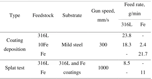
splat tests were performed by spraying 316L or Fe powder onto the single component 316L and
Fe coatings. The coatings used as substrates for splat tests all have a thickness of about 1 mm in
order to eliminate the effect of the mild steel substrate, and they were polished beforehand to a
mirror surface. The process details regarding coating deposition and splat tests are shown in
Table 2.
After coating deposition, DE was measured as the mass gain of the substrate divided by
6
characterized by a Hitachi SU3500 SEM (Hitachi, Tokyo, Japan). After splat tests, micrographs
of coating surfaces and splats were observed by SEM. The splat deposition behavior was
evaluated using bond ratio (BR). As previously discussed in [26], BR was determined as the
average value of the fraction of the number of bonded particles (splats) to the total incident
particles (splats+craters). The splats and craters from about 3-5 SEM images of the center of spray line with a field of 640×480 μm were counted for each impact scenario. The total numbers of splats+craters in a single image are about 240-300 for 316L impact and about 130-180 for Fe
impact. The degree of splat deformation was evaluated by the flattening ratio, which was
calculated as the width over the height of a cross-sectioned splat. The degree of coating
deformation was evaluated by a fraction of the depth of the crater over its diameter using a Zygo
NewView 8000 optical profilometer (Zygo Corp., Middlefield, USA). Over 30 splats and craters
were measured to calculate the respective flattening ratio and coating crater depth/diameter, and
the average values were reported.
Splat adhesion tests were performed in reference to [24, 27] using a Micro-Combi Scratch
Tester (CSM Instruments Inc., Needham, USA) equipped with a wedge shaped stylus. Prior to
testing, the average diameter of splat was measured by the integrated LOM to calculate the splat
area (A). During tests, a constant normal force, FN, of 100 or 300 mN was applied onto the stylus,
which is 100 μm in the tip width. The substrate was moving at a 150 μm/min rate below the stylus to create a shearing behavior. When the stylus encountered the splat edge, the tangential
force (� ) gradually increased to a peak and then dropped sharply at splat failure (see Fig. 2). For each sample, between four to eight splats of 40 to 50 μm in diameter were shear tested. After testing, the adhesion strength was calculated using the peak tangential force (� � � ) subtracting the baseline tangential force (� � � ). The adhesion energy (an energy required to debond the splat) was calculated by integrating the area under tangential force curve.
7
This was normalized to the projected area of the splat (A). Similarly, the baseline friction force
area was subtracted from the peak.
Adhesion strength = � � � − � � (1) Adhesion energy =∫����� ���� � � − � � �
� � � (2)
2.2 FE simulations
A 2D Lagrangian axisymmetric model was used to obtain the splat rebound behavior
during impact using the FE analysis software ABAQUS/Explicit (version 6.11-1) [28]. The size
of the feedstock was set to be the same as the one listed in Table 1. The velocities of the
feedstocks were set at 585 m/s for 316L and 600 m/s for Fe, which were measured by a
Coldspraymeter particle diagnostic system (Tecnar Automation, St. Bruno, CA) [20]. The
dimensions of the substrate were set to be 10 times the particle radius to eliminate influence from
boundary conditions. A 4-node bilinear plane strain quadrilateral mesh (CPE4R) was used for the
simulation. A convergence study was carried out and a meshing resolution of 1/50 Dp (diameter
of the particle) was considered for the particle and the substrate. This meshing resolution has
been used in earlier studies [29, 30]. Distortion and hourglass controls were kept at default
settings. Symmetry boundary conditions were imposed on the sides of the particle and substrate,
while the bottom of the substrate was fixed. The elastic response of the material was assumed
isotropic while the plastic response of the material was described by the Johnson-Cook plasticity
model [31].
� = [ + � ][1 + ln �̇∗][1 − �∗ ] (3)
8
where � is the flow stress, � is the equivalent plastic strain (PEEQ) defined as � = ∫ √ �̇ : �̇0 , with �̇ being the plastic strain rate, �̇∗ is the equivalent plastic strain rate normalized by a reference strain rate, � is the reference temperature and � is the melting temperature [25, 29, 30, 32]. In our simulations the deformation process is considered to be
adiabatic due to the high rate of deformation, as previously explained by Assadi et al. [29]. The
initial temperature of both the particle and substrate is kept at room temperatures (298K). The
material properties and parameters for the Johnson-Cook model are tabulated in Table 3 [33, 34].
To obtain the splat rebound behavior, the splat recoil coefficient e was determined. Recoil coefficient e defines the proportion of the particle kinetic energy to be rebounded upon impact due to elastic recovery and is given as [35]:
= 11.47 (�� ∗) �
−
�− (5)
where ρ , m , and v are respectively, the density, particle weight, and velocity of impacted particles, �� is the particle effective yield stress during impact determined from FE simulations, and E∗ is an elastic modulus that is experienced during particle impact.
3. Results
9
The DE and BSE images of the single component 316L and Fe coatings are shown in Fig.
3. The 316L coating (Fig. 3 (a)) reveals small amounts of porosity (black regions) while the Fe
(Fig. 3 (b)) has a dense structure. In cold sprayed coatings, the native oxide scales of the
feedstock powder will be included and are presented between particles delineating as the
interparticle boundaries (dark lines). By observing the interparticle boundaries of the 316L and
Fe, a significant difference is revealed. The Fe/Fe particle interfaces in Fig. 3 (b) are seen to be
wider and more clearly delineated compared to the 316L/316L interfaces in Fig. 3 (a), indicating
a poorer interfacial bonding of the Fe coating than 316L. This feature can be attributed to the
high oxidation susceptibility of the Fe particles, and also appears to be consistent with a slightly
inferior DE of the single component Fe to that of 316L (50% vs 55%). EDS scans were then
performed on the 316L and Fe coatings at interparticle regions and also inner particle regions as a
reference. As shown in Figs. 3 (c) and (d), the EDS spectra indicate the presence of oxygen at
interparticle regions and the complete absence at inner particle regions. Thus, it is suggested that
the dark lines in BSE images represent the oxide scale on the powder surface, and the Fe has a
thicker oxide scale compared with 316L.
The DE and BSE image of the 10Fe composite coating are shown in Fig. 4. The impact
direction is indicated by the white arrow, and the dark regions are Fe, the light regions are 316L,
and the black spots are pores. For the 10Fe composite coating, the mixed 316L/Fe interfaces are
generated. Firstly, comparing the non-mixed 316L/316L regions in 10Fe (Fig. 4) with those in
single component 316L (Fig. 3 (a)), very similar optical characteristics, with few visible
interparticle boundaries, are observed. This implies a blend of 10 wt.% Fe powder in the mixture
has not affected the interfacial bonding of the matrix 316L powder in 10Fe. By looking at the
mixed 316L/Fe interfaces in 10Fe, cracks are observed, as shown in Fig. 4, perpendicular to the
10
interparticle bonding and/or a strong rebound of the impacted particles, which appears to explain
the low DE of 10Fe (38%). It is also noticed that, the inter-lamellar cracks would mostly locate on the “top” of Fe and the “bottom” of 316L, as marked by red arrows. This observation implies a stronger rebound of 316L particles impacting on the previously deposited Fe compared with Fe
on 316L.
3.2 Characterization of splats
3.2.1 Splat morphology
The desire to explain the feedstock deposition behavior, especially at the mixed interfaces,
leads to the effort of performing splat tests onto coatings. The coating SEM morphologies after
splat tests are shown in Fig. 5. Four types of impact scenarios are generated, referred to as 316L
on 316L, 316L on Fe, Fe on 316L and Fe on Fe below.
Results show that the different splat impact scenarios between the 316L and Fe give
significantly different splat morphologies. For 316L on Fe (Fig. 5 (b)), some splats have shown
an obvious lifting off at the edges (circled in red). However, the opposite case Fe on 316L (Fig. 5
(c)), reveals splats all being closely attached to the coating surface. This finding correlates with
the previous observation of the preferential location of inter-lamellar cracks at the 316L/Fe mixed
interfaces (Fig. 4). As for the impacts between same material, i.e. 316L on 316L and Fe on Fe, it
appears the 316L splats exhibit a closer contact to 316L surface than Fe to Fe, as the latter case
also exhibits some splats with lifted edges (circled in red in Fig. 5 (d)). This phenomenon is also
consistent with the poorer interfacial bonding of Fe/Fe than 316L/316L, as previously observed
in Figs. 4 (a) and (b). Therefore, it is considered that the splat on coating tests can be indicative of
11
3.2.2 Splat deposition and deformation behavior
To quantify the splat deposition behavior, the bond ratio (BR) for each impact scenario is
plotted in Fig. 6 (a). The BR results explicitly show the distinct deposition behavior of impacts
between dissimilar materials, i.e. 316L on Fe and Fe on 316L (8% vs 87%); whereas the
deposition behavior of impacts between the same material is relatively similar (316L on
316L-45%, Fe on Fe-38%).
To explain the splat deposition behavior, the deformation levels of the splat and the
coating were both quantified. The splat deformation behavior shown in Fig. 6 (b) was evaluated
using the common approach flattening ratio. The coating deformation shown in Fig. 6 (c) was
evaluated by the average ratio of the depth of a crater over its diameter. It is believed this metric
can normalize the effects of particle size and particle deforming on the coating deformation.
Results show that the average FR values have a positive correlation with the BR results. The FR
values can be explained by the relative particle/coating hardness, where a high FR is obtained
from a soft particle impacting on the hard coating, e.g. Fe on 316L. Note that for the Fe splats
with some irregular shape fractions, the splat FR might not reveal the actual particle deformation
and is simply the splat aspect ratio. But it is believed that a high splat aspect ratio should
similarly create a large particle/coating contact to facilitate deposition. As opposed to the splat
deformation, in general, no correlations between the coating crater depth/diameter values and
splat BR can be observed.
The rebound trend of a splat during impact was evaluated by the recoil coefficient e , which was determined from FE simulations (Section 2). The results for each impact scenario are
12
than Fe on 316L (0.05), which implies a higher proportion of the splat kinetic energy is
transformed to initiate the splat rebound upon impact for the former case. This explains the
preferential location of inter-lamellar cracks in the 10Fe coating (Fig. 4) and also the lower BR of
316L on Fe than Fe on 316L (Fig. 6 (a)). However, the recoil coefficient metric is observed to fail
to explain the different BR of a splat onto 316L and Fe coatings (e.g. 316L on 316L and 316L on
Fe have the same e but different BR). This finding implies that, apart from rebound, there might be other factors affecting the splat deposition to occur, e.g. adhesion, which will be discussed in
Section 3.2.3.
3.2.3 Splat adhesion strength/energy
To quantify and compare the relative splat bond strength between different impact
scenarios, the splat adhesion testing was performed. The experimental approach used in this study
was similar to the previous investigators Goldbaum et al. [24, 27], but the splats being measured
were deposited onto as-polished cold sprayed coatings instead of the bulk material substrate. The
typical load-displacement curve for each impact scenario and the respective SEM morphology of
the failure region are shown in Fig. 7. Results show three main types of splat shearing behavior of
the different impact scenarios between 316L and Fe can be observed.
The first type, which is seen in 316L on Fe, shows only a small rise in the tangential force
with tip displacement, indicating a poor splat adhesion strength. The failure region exhibits a
presence of crater with an approximate size of the original splat (contour circled in red). No
visible shear tracks are observed in the crater. This indicates the splat adhesion was mainly
13
The second type, which is illustrated by Fe on Fe and 316L on 316L, shows the failure
regions revealing a crater, but its size is smaller than the original splat (contour circled in red).
The difference in radius between the crater and original splat is roughly the width of the
tangential force peak. The peripheral regions where the shearing events mainly took place implies
the formation of metallurgical bond in these regions. Examination of the respective
load-displacement curves, however, reveals some different situations. For Fe on Fe, the tangential
force peak appears to be higher and wider than the 316L on Fe (first type), but the difference is
not significant. However, for 316L on 316L, there was a sharp rise in the tangential force and
then followed by a rapid drop, and the peak tangential force has reached a high value of about
360 mN.
Finally, the third type is the Fe on 316L. It can be seen the sheared region gives a full
outline of the splat and the width of the tangential peak is roughly the width of the original splat
(contour circled in red). This type of phenomenon is considered to be comparable to the behavior
of shearing a bulk material, and thus the splat is expected to have a high adhesion strength
approaching the theoretical shear strength of the materials at the counterpart. Compared with the
previous case 316L on 316L (second type), the peak value of the tangential force is lower, but
there is a much smoother rise and drop. This feature could indicate either a higher proportion of
the metallurgical bond formation or degree of particle deformation during the Fe impact.
To further investigate the splat bonding features, the crater surfaces within the failure
regions are shown in Fig. 8. For Fe on 316L (Fig. 8 (c)), a less well bonded splat (adhesion
strength of 125 MPa) exhibiting the second type failure is presented instead. For 316L on 316L,
some textures are observed at the crater surface. Considering that such features should not be
resulted by the splat impact since the 316L powder has a smooth surface (Fig. 1), it is believed
14
Fe, similarly, textures can also be observed in the crater surfaces, but appear to be finer than
those in 316L on 316L. For Fe on Fe, however, the crater surface appears to be relatively smooth,
which implies the adhesion in the crater was simply the weak conformal bonding.
The adhesion strength and adhesion energy of each impact scenario were calculated from
the respective load-displacement curve and are plotted in Fig. 9. As for the adhesion strength, the
316L on 316L (215 MPa) and Fe on 316L (167 MPa) are the two highest types, while the Fe on
Fe and 316L on Fe types are the two lowest ones (<50 MPa). Regarding the adhesion energy, the
Fe on 316L with a smooth shear curve (Fig. 7) exhibits the highest adhesion energy, even higher
than 316L on 316L (3 vs 1.6 kJ/m2) despite its adhesion strength is lower (167 vs 215 MPa).
Whereas the 316L on Fe and Fe on Fe types still exhibit a similar relative magnitude and remain
the two lowest ones in adhesion energy. Moreover, it is noticed that the adhesion energy plots
exhibit a positive correlation with the bond ratio results (Fig. 6 (a)). This results, combined with
the rebound coefficient plots (Fig. 6 (d)), demonstrate the dominant contribution of adhesion
energy in determining the splat BR.
4. Discussion
Previous results (Fig. 6 (a)) have shown the distinct splat deposition behavior between the
four impact scenarios, especially for impacts between the dissimilar materials (316L on Fe and Fe
on 316L), which corresponds to the mixed interface inter-lamellar cracks in the 10Fe coating (Fig.
4). To explain the splat deposition behavior, the powder characteristics (Table 1) and material
properties (e.g. Table 3) of the feedstock were investigated. A few disparities between the 316L
and Fe feedstocks are identified to be the contributing factors, i.e. hardness, surface oxide layer,
15
Hardness indicates the ability of a material to resist the plastic deformation. Generally in
cold spray, the soft particle can exhibit a high degree of deformation (e.g. flattening) during
impact, which enlarges the particle/substrate interface contact to facilitate the mechanical
anchorage effect [24, 36]. The high level of deformation at the interfaces can also help to disrupt
the surface oxide layer and provide a direct metal-metal contact favoring the metallic bond
formation [36, 37]. In this study, the 316L powder has almost double the microhardness of the Fe
(262.6 HV0.01 vs 141.3 HV0.01). As the coatings on which splats deposit are the work hardened
particle layers, most of the splat impact scenarios are categorized as the soft on hard case [30].
Thus, during cold spray, deformation at the impact interfaces tends to be mostly localized at the
particle side rather than the coating. Comparing the impacts between dissimilar materials, the Fe
on 316L type with a higher BR than 316L on Fe (87% vs 8%), corresponds to a higher particle
FR (2.7 vs 2.2) and a shallower coating penetration (0.118 vs 0.144). Thus, it is considered for
the soft on hard case, as the substrate is reluctant to deform during impact, the particle
deformation can be more effective than the substrate deformation in facilitating particle
deposition.
The splat deposition is considered as a competition between adhesion and rebound [35].
The hardness and the hardening behavior of the feedstock material also affect the rebound
behavior of a splat during impact. According to Eq 5, a higher recoil coefficient (stronger
rebound) is associated with a higher dynamic yield strength of a particle, which is determined by
its static yield strength and the increment from effects of strain hardening, strain rate hardening
and thermal softening during the kinetic impact process (Eq 3). As opposed to Fe, the 316L with
a higher particle hardness implies a higher static yield strength, and its larger strain hardening
parameter B and n (Table 2) also indicate a more rapid strain hardening behavior of the 316L
16
inter-lamellar cracks at the 316L/Fe interfaces) and the lower BR (8% vs 87%), as compared with
the Fe on 316L case.
During cold spray, the formation of adiabatic shear instabilities (e.g. metal jetting) at
impact interfaces is an effective material behavior to remove the interfacial oxide layer, and the
accompanying heat can induce a locally molten region to form strong metallurgical bond [36].
However, the jetting phenomenon of the deposited splats is not clearly observed in any of the
four cases (Fig. 5). This observation implies that, under these cold spray conditions, there will be
a significant interfacial oxide layer effect. The chromium content in 316L can form a thin but
tenacious chromium surface oxide layer to protect the inner material from further oxidation [38,
39]; while the iron oxide is reported to be unstable/porous in nature [40] thus the oxide film tends
to be thicker in Fe. The difference in the oxide film thickness between 316L and Fe can be
indicated by the different interparticle boundary conditions shown in Fig. 3. Evidence of the
effect of oxide layer interference was found at the crater surfaces within the sheared regions (Fig.
8), where the Fe/Fe crater surfaces are smoother than any interfaces involving the 316L. This
implies that metallurgical bonding is inhibited in the Fe/Fe case, which could be due to the
thicker oxide layer being harder to disrupt during impact. The difference in surface oxide film
thickness between the 316L and Fe feedstocks can contribute to the ease of particle deposition
(higher BR) on the 316L coating as opposed to the Fe coating (Fig. 6 (a)).
In the adhesion strength/energy plots (Fig. 9), comparing the Fe on 316L with 316L on
316L, it is noticed that the former case has a lower adhesion strength (167 vs 215 MPa) but its
adhesion energy is almost double that of the latter (3 vs 1.6 kJ/m2). The high adhesion energy in
Fe on 316L is attributed to its bulk-like shearing behavior during testing (Fig. 7), which implies
the occurrence of either a higher proportion of metallurgical bond formation or degree of particle
17
presence in the Fe feedstock, theoretically the metallurgical bond formation in the Fe on 316L
case should be less favored than in 316L on 316L. Also, the difference in splat deformation (splat
FR: Fe on 316L-2.66 vs 316L on 316L-2.50) appears not significant enough to result in such
different shearing behavior. Thus, it is believed there is a significant effect of the irregular splat
morphology on the splat adhesion. As reported in literature, the large surface area provided by the
irregular powder could increase the particle/substrate contact during deposition, thus the
mechanical interlocking effect is enhanced (compared with spherical ones) [41]. Also, the
irregular morphology increases the stress concentration at the particle surface during impact,
which is expected to facilitate the localized shear deformation and disruption of the surface oxide
layer to help the metallurgical bond formation [41]. However, the contribution of the irregular
morphology on the splat adhesion has not yet been quantitatively determined.
Overall, this study presents an approach of performing splats tests onto as-polished
coatings to investigate the mixed powder deposition behavior, which is often difficult to interpret
from coating microstructure. Theoretically, this approach can be extended to investigate powder
mixtures of any number of components. However, it is understood that there might be issues of
using this approach. Firstly, the splat on coating tests have avoided the effects of roughness and
tamping which will occur during the actual coating deposition. This simplification was justified
in this case as the 316L and Fe feedstocks are similar in the particle size, velocity and density
(Section 2). However, for other mixtures, e.g. hard/soft and large/small, where the tamping or
retention effect of the component powder tends to be significant, the splat deposition behavior
might not be indicative of the coating build-up process. Secondly, in order to investigate the 10Fe
composite coating build-up process, the most straightforward approach is to directly spray single
particles onto the as-polished 10Fe coatings. However, in this study an indirect approach was
18
the specific impact scenarios. This thus generates a concern of the effect of different substrates on
the splat deposition. Relevant studies will be carried out in the future.
5. Conclusion
In this study, single component 316L, Fe, and a composite 10Fe coatings were cold spray
deposited. A preferential location of inter-lamellar cracks was observed at the mixed 316L/Fe
interfaces in the 10Fe coating. Splat tests were performed onto the as-polished single component
316L and Fe coatings and four types of impact scenarios (316L on 316L, 316L on Fe, Fe on 316L
and Fe on Fe) were studied. Similar bonding features were observed in the deposited splats and
cold spayed coatings, showing the splat on coating tests to be indicative of the coating build-up
process. To investigate the feedstock deposition behavior in the 10Fe coating, experimental
characterizations (deformation, adhesion) and FE simulations (rebound behavior) of the splats
were performed. Finally, the feedstock deposition behavior in the 10Fe coating was explained
from hardness, surface oxide layer, and particle morphology.
Acknowledgements
The authors acknowledge the McGill Engineering Doctoral Awards (MEDA) and Natural
Sciences and Engineering Research Council of Canada (NSERC) for the financial support. The
19
access to the machine for splat adhesion tests. The authors thank Prof. Richard Chromik at
McGill University for access to the optical profilometer.
References
[1] C.-J. Li, G.-J. Yang, P.-H. Gao, J. Ma, Y.-Y. Wang, C.-X. Li, Characterization of nanostructured WC-Co deposited by cold spraying, J. Therm. Spray Technol. 16 (2007) 1011-1020.
[2] H.-J. Kim, C.-H. Lee, S.-Y. Hwang, Fabrication of WC–Co coatings by cold spray deposition, Surf. Coat. Technol. 191 (2005) 335-340.
[3] N. Melendez, A. McDonald, Development of WC-based metal matrix composite coatings using low-pressure cold gas dynamic spraying, Surf. Coat. Technol. 214 (2013) 101-109.
[4] P.-H. Gao, C.-J. Li, G.-J. Yang, Y.-G. Li, C.-X. Li, Influence of substrate hardness transition on built-up of nanostructured WC–12Co by cold spraying, Appl. Surf. Sci. 256 (2010) 2263-2268. [5] P.-H. Gao, Y.-G. Li, C.-J. Li, G.-J. Yang, C.-X. Li, Influence of powder porous structure on the deposition behavior of cold-sprayed WC-12Co coatings, J. Therm. Spray Technol. 17 (2008) 742-749.
[6] R. Lima, J. Karthikeyan, C. Kay, J. Lindemann, C. Berndt, Microstructural characteristics of cold-sprayed nanostructured WC–Co coatings, Thin solid films 416 (2002) 129-135.
[7] K.J. Hodder, J.A. Nychka, A.G. McDonald, Comparison of 10 μm and 20 nm Al-Al2O3 Metal Matrix Composite Coatings Fabricated by Low-Pressure Cold Gas Dynamic Spraying, J. Therm. Spray Technol. 23 (2014) 839-848.
[8] H. Koivuluoto, P. Vuoristo, Effect of Powder Type and Composition on Structure and Mechanical Properties of Cu + Al2O3 Coatings Prepared by using Low-Pressure Cold Spray Process, J. Therm. Spray Technol. 19 (2010) 1081-1092.
[9] K. Spencer, D.M. Fabijanic, M.X. Zhang, The influence of Al2O3 reinforcement on the properties of stainless steel cold spray coatings, Surf. Coat. Technol. 206 (2012) 3275-3282.
[10] H.Y. Lee, S.H. Jung, S.Y. Lee, Y.H. You, K.H. Ko, Correlation between Al2O3 particles and interface of Al–Al2O3 coatings by cold spray, Appl. Surf. Sci. 252 (2005) 1891-1898.
[11] Y. Tao, T. Xiong, C. Sun, H. Jin, H. Du, T. Li, Effect of α-Al2O3 on the properties of cold sprayed Al/α-Al2O3 composite coatings on AZ91D magnesium alloy, Appl. Surf. Sci. 256 (2009) 261-266.
20
[12] X.-k. Wu, X.-l. Zhou, H. Cui, X. Zheng, J.-s. Zhang, Deposition Behavior and Characteristics of Cold-Sprayed Cu-Cr Composite Deposits, J. Therm. Spray Technol. 21 (2012) 792-799.
[13] H. Che, X. Chu, P. Vo, S. Yue, Cold spray of mixed metal powders on carbon fibre reinforced polymers, Surf. Coat. Technol. 329 (2017) 232-243.
[14] A. Sova, R. Maestracci, M. Jeandin, P. Bertrand, I. Smurov, Kinetics of composite coating formation process in cold spray: Modelling and experimental validation, Surf. Coat. Technol. 318 (2017) 309-314.
[15] A. Moridi, S.M. Hassani-Gangaraj, M. Guagliano, M. Dao, Cold spray coating: review of material systems and future perspectives, Surf. Eng. 30 (2014) 369-395.
[16] S. Grigoriev, A. Okunkova, A. Sova, P. Bertrand, I. Smurov, Cold spraying: From process fundamentals towards advanced applications, Surf. Coat. Technol. 268 (2015) 77-84.
[17] X.-T. Luo, Y.-K. Wei, Y. Wang, C.-J. Li, Microstructure and mechanical property of Ti and Ti6Al4V prepared by an in-situ shot peening assisted cold spraying, Materials & Design 85 (2015) 527-533.
[18] R.G. Maev, V. Leshchynsky, Air gas dynamic spraying of powder mixtures: theory and application, J. Therm. Spray Technol. 15 (2006) 198-205.
[19] H. Koivuluoto, P. Vuoristo, Effect of Ceramic Particles on Properties of Cold-Sprayed Ni-20Cr+Al2O3 Coatings, J. Therm. Spray Technol. 18 (2009) 555-562.
[20] E. Irissou, J.-G. Legoux, B. Arsenault, C. Moreau, Investigation of Al-Al2O3 cold spray coating formation and properties, J. Therm. Spray Technol. 16 (2007) 661-668.
[21] H. Aydin, M. Alomair, W. Wong, P. Vo, S. Yue, Cold Sprayability of Mixed Commercial Purity Ti Plus Ti6Al4V Metal Powders, J. Therm. Spray Technol. 26 (2017) 1-11.
[22] T. Van Steenkiste, J. Smith, R. Teets, Aluminum coatings via kinetic spray with relatively large powder particles, Surf. Coat. Technol. 154 (2002) 237-252.
[23] Y. Xiong, G. Bae, X. Xiong, C. Lee, The Effects of Successive Impacts and Cold Welds on the Deposition Onset of Cold Spray Coatings, J. Therm. Spray Technol. 19 (2009) 575-585.
[24] D. Goldbaum, J.M. Shockley, R.R. Chromik, A. Rezaeian, S. Yue, J.-G. Legoux, E. Irissou, The Effect of Deposition Conditions on Adhesion Strength of Ti and Ti6Al4V Cold Spray Splats, J. Therm. Spray Technol. 21 (2011) 288-303.
[25] F. Meng, S. Yue, J. Song, Quantitative prediction of critical velocity and deposition efficiency in cold-spray: A finite-element study, Scr. Mater. 107 (2015) 83-87.
21
[26] X. Chu, H. Che, P. Vo, R. Chakrabarty, B. Sun, J. Song, S. Yue, Understanding the cold spray deposition efficiencies of 316L/Fe mixed powders by performing splat tests onto as-polished coatings, Surf. Coat. Technol. 324 (2017) 353-360.
[27] R.R. Chromik, D. Goldbaum, J.M. Shockley, S. Yue, E. Irissou, J.-G. Legoux, N.X. Randall, Modified ball bond shear test for determination of adhesion strength of cold spray splats, Surf. Coat. Technol. 205 (2010) 1409-1414.
[28] D. Simulia, Abaqus 6.11 analysis user’s manual, Abaqus 6.11 Documentation (2011) 22.22. [29] H. Assadi, F. Gärtner, T. Stoltenhoff, H. Kreye, Bonding mechanism in cold gas spraying, Acta Materialia 51 (2003) 4379-4394.
[30] G. Bae, Y. Xiong, S. Kumar, K. Kang, C. Lee, General aspects of interface bonding in kinetic sprayed coatings, Acta Materialia 56 (2008) 4858-4868.
[31] G.R. Johnson, W.H. Cook, A constitutive model and data for metals subjected to large strains, high strain rates and high temperatures, Proceedings of the 7th International Symposium on Ballistics, The Hague, The Netherlands, 1983, pp. 541-547.
[32] M. Grujicic, C.L. Zhao, W.S. DeRosset, D. Helfritch, Adiabatic shear instability based mechanism for particles/substrate bonding in the cold-gas dynamic-spray process, Materials & Design 25 (2004) 681-688.
[33] A.A. Olleak, M.N. Nasr, H.A. El-Hofy, The Influence of Johnson-Cook Parameters on SPH Modeling of Orthogonal Cutting of AISI 316L, (2015).
[34] O. Bielousova, J. Kocimski, R.G. Maev, I. Smurov, W. Scharff, V. Leshchynsky, Localisation of deformation in cold gas dynamic spraying, Surf. Eng. 32 (2016) 655-662.
[35] J. Wu, H. Fang, S. Yoon, H. Kim, C. Lee, The rebound phenomenon in kinetic spraying deposition, Scr. Mater. 54 (2006) 665-669.
[36] T. Hussain, D.G. McCartney, P.H. Shipway, D. Zhang, Bonding Mechanisms in Cold Spraying: The Contributions of Metallurgical and Mechanical Components, J. Therm. Spray Technol. 18 (2009) 364-379.
[37] T. Samson, D. MacDonald, R. Fernández, B. Jodoin, Effect of Pulsed Waterjet Surface Preparation on the Adhesion Strength of Cold Gas Dynamic Sprayed Aluminum Coatings, J. Therm. Spray Technol. 24 (2015) 984-993.
[38] P.S. Korinko, S.H. Malene, Considerations for the weldability of types 304L and 316L stainless steel, Practical Failure Analysis 1 (2001) 61-68.
[39] S. Tardio, M.-L. Abel, R.H. Carr, J.E. Castle, J.F. Watts, Comparative study of the native oxide on 316L stainless steel by XPS and ToF-SIMS, Journal of Vacuum Science & Technology A: Vacuum, Surfaces, and Films 33 (2015) 05E122.
22
[40] C. Leygraf, I.O. Wallinder, J. Tidblad, T. Graedel, Atmospheric Corrosion, Wiley, 2016.
[41] L. Ajdelsztajn, B. Jodoin, J.M. Schoenung, Synthesis and mechanical properties of nanocrystalline Ni coatings produced by cold gas dynamic spraying, Surf. Coat. Technol. 201 (2006) 1166-1172.
Table 1 Characteristics of the feedstock powder.
Powder Morphology Size, μm Microhardness, HV0.01
316L Spherical 22.2 262.6
23
Table 2 Process details for coating deposition and splat tests.
Type Feedstock Substrate Gun speed, mm/s Feed rate, g/min 316L Fe Coating deposition 316L Mild steel 300 23.8 - 10Fe 18.3 2.4 Fe - 21.7
Splat test 316L 316L and Fe
coatings 1000
8.5 -
24
Table3 Material properties and parameters for the Johnson-Cook model [33, 34].
Properties Parameter Unit Value 316L Fe General Density kg/m 8000 7890 Specific heat J/kg · � 500 452 � K 1668 1811 Elastic Young’s modulus GPa 193 207 Poison’s ratio − 0.27 0.29 Plastic MPa 514 175 MPa 514 380 − 0.508 0.32 − 0.042 0.06 − 0.533 0.55 � K 293 293
25
Figure captions
Fig. 1 SEM images of the feedstock powders.
Fig. 2 Optical images of a splat before (top left) and after shearing (bottom left), and the
respective load-displacement curve.
Fig. 3 SEM/EDS analyses on 316L (DE-55%) and Fe (DE-50%): (a) BSE image of 316L, (b)
EDS spectrum of 316L, (c) BSE image of Fe, and (d) EDS spectrum of Fe.
Fig. 4 BSE image of 10Fe (DE-38%). Red arrows: inter-lamellar cracks at the mixed 316L/Fe
interfaces.
Fig. 5 SEM coating morphology after splat tests: (a) 316L on 316L, (b) 316L on Fe, (c) Fe on
316L, and (d) Fe on Fe.
Fig. 6 The (a) bond ratio, (b) splat flattening ratio, (c) coating crater depth/size, and (d) recoil
26
Fig. 7 Typical tangential force vs displacement curve with the respective SEM image of the
failure region for each impact scenario (Red circles: contours of the original splats).
Fig. 8 High magnification SEM morphology of the crater failure surface: (a) 316L on 316L, (b)
316L on Fe, (c) Fe on 316L, and (d) Fe on Fe.
Fig. 9 Splat adhesion strength and adhesion energy for each impact scenario.
27
28
29
30
31
32
33
Fig. 8
![Table 3 Material properties and parameters for the Johnson-Cook model [33, 34].](https://thumb-eu.123doks.com/thumbv2/123doknet/14052800.460382/25.918.252.710.550.903/table-material-properties-parameters-johnson-cook-model.webp)

