Applications of Computer-Controlled Actuation in
Workbench Tangible User Interfaces
by
Daniel Maynes-Aminzade
Submitted to the Department of Media Arts and Sciences,
in partial fulfillment of the requirements for the degree of
Master of Science in Media Arts and Sciences
at the
MASSACHUSETTS INSTITUTE OF TECHNOLOGY
May 13, 2003
© Massachusetts Institute of Technology, 2003. All Rights Reserved.
Author ...
Certified by ...
... 1/.. ... ...
Daniel Maynes-Aminzade
Program in Media Arts and Sciences
May 13, 2003
Hiroshi Ishii
Associate Professor of Media Arts and Sciences
I
Thesis Supervisor
A ccepted by ...
y
...
... ...
Andrew Lippman
Chair, Departmental Committee on Graduate Students
Program in Media Arts and Sciences
MASSACHU OF TE
ROTCHJUL
LIB
SETTS INSTITUTE CHNOLOGY 14 2003
RARIESApplications of Computer-Controlled Actuation in Workbench Tangible
User Interfaces
by
Daniel Maynes-Aminzade
Submitted to the Department of Media Arts and Sciences on May
16, 2003, in partial fulfillment of the requirements for the degree of
Master of Science in Media Arts and Sciences
Abstract
Tangible user interfaces give physical form to digital information, bridging the gap
between the digital world of bits and the physical world of atoms. They offer many advan-tages over traditional graphical user interfaces, including two-handed manipulation, sim-plified multi-user collaboration, and the use of natural human spatial and tactile abilities. In the majority of existing tangible interfaces, different modalities are used for input and output; while the user provides input through the manipulation of physical objects, the computer produces only graphical output. This can lead to inconsistencies between the digital and physical representations of the same object. The goal of this thesis is to address this limitation by adding computer-controlled actuation to tangible interfaces. Actuation allows the computer to manipulate graspable objects the same way that a human user can.
By developing and evaluating a variety of applications that use actuation, we demonstrate
how it can best be employed in tangible interfaces. Thesis Supervisor: Hiroshi Ishii
Applications of Computer-Controlled Actuation in
Workbench Tangible User Interfaces
by
Daniel Maynes-Aminzade
T hesis Supervisor ...
.. ...
...
Hiroshi Ishii
Associate Professor of Media Arts and Sciences
Milysachusetts Institute of Technology
Thesis Reader ...
... ... .. .. .. .. .. .. .. .. .. .. .. .. .. .Robert Jacob
Associate Professor of Computer Science
Tufts University
T hesis R eader ...
...
.
... ....
Chris Schmandt
Principal Research Scientist
Massachusetts Institute of Technology
Table of Contents
1 Introduction...8
1.1 Tangible User Interfaces... 8
1.2 Interactive W orkbenches ... 9
1.3 Inconsistencies in Tangible Interfaces ... 10
1.4 Preventing Inconsistency ... 11
1.5 Research Approach and Thesis Overview ... 12
2 Background and Related W ork... 14
2.1 Interactive Surfaces... 14
2.2 Two-Dim ensional Actuation Technologies ... 16
2.3 Haptic and Force Feedback Interfaces... 18
2.4 Kinesthesia, Proprioception, Memory, and Perceptual Psychology ... 19
3 Hardware and Software Design ... 22
3.1 Design Parameters ... 22
3.2 M echanical Design ... 23
3.3 Circuit Design and Hardware-Software Interface... 24
3.4 Puck Design ... 25
3.5 Object Tracking and Position Sensing... 26
3.6 M otion Control and Interpolation... 29
3.7 Anti-Aliasing Techniques ... 32
4 Applications ... 35
4.1 Types of Applications...35
4.2 Extending GUI Functions to the Physical Domain... 35
4.3 Navigation... 36
4.4 Remote Synchronization... 37
4.5 Scientific Visualization... 39
4.6 Entertainment... 39
4.7 Specifying and M aintaining Constraints... 40
4.8 Computer M ovement vs. User M ovement... 43
4.10 Resolving Conflicts in Rem ote Collaboration ... 44 5 Conclusion ... 46 5.1 Sum m ary ... 46 5.2 M aintaining Constraints... 46 5.3 Haptic Feedback ... 47 5.4 Spatial Thinking... 47
5.5 Rem ote Collaboration ... 48
5.6 Future V ision ... 49
A ppendix A M athem atical Derivations ... 50
A. 1 M otion Control Equations ... 50
A ppendix B Engineering Im provem ents ... 53
B. Tiling of A ctuation Surfaces and Scale ... 53
B.2 Puck M odifications ... 53
B.3 N ew Types of M otion... 53
Appendix C Softw are Im provem ents ... 55
C. Coordinating M ultiple Objects ... 55
C.2 Unified Softw are Architecture... 55
Appendix D N ew D irections for A ctuation ... 57
D .1 Types of A ctuated Interfaces ... 57
D .2 Purpose of A ctuated Feedback ... 57
D .3 Spatial Com plexity and D egrees of Freedom ... 58
List of Figures
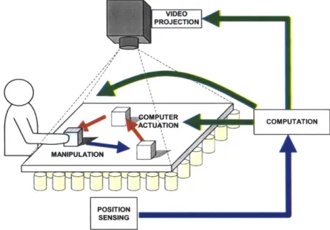
Figure 1.1: Traditional interactive workbench systems provide feedback through video pro-jection alone. The Actuated Workbench adds an additional feedback loop using physical
m ovem ent of the tracked objects. ... 10
Figure 1.2: Addressing the nulling problem . ... 12
Figure 2.3: Conceptual sketch of Bricks system...14
Figure 2.1: Digital Desk (calculator application) ... 14
Figure 2.6: The BUILD-IT system for floor planning combined 2D and 3D views...15
Figure 2.2: The GraspDraw application (left) used a tool palette and inkwell (right).... 15
Figure 2.4: The metaDESK system used physical icons and lenses to navigate and explore geographical spaces. ... 15
Figure 2.5: The "Real Reality" system for assembly line planning...15
Figure 2.7: Urp, a tangible workbench for urban planning. ... 16
Figure 2.8: The Sensetable platform has been used for supply chain visualization (left) and m usical perform ance (right)... 16
Figure 3.1: Our basic actuation platform contains a grid of 64 computer-controlled electro-m agn ets...22
Figure 3.2: Overhead view of electromagnet array. ... 23
Figure 3.3: Custom-wound electromagnets produce broad, uncontained magnetic field s...2 3 Figure 3.4: Custom-fabricated circuit board containing flip-flops and H-bridge transistor array s... ... ---.-... 24
Figure 3.5: Our initial puck design included a permanent magnet and an infrared LED for vision tracking...25
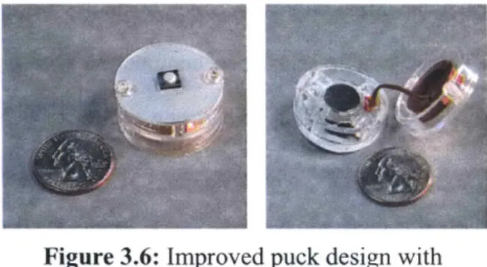
Figure 3.6: Improved puck design with momentary pushbutton switch (top); exploded view of puck showing permanent magnet and LC tag (bottom). ... 26
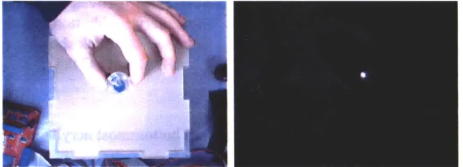
Figure 3.7: Overhead view of the Actuated Workbench from vision camera without IR filter (left) and w ith IR filter (right)... 27
Figure 3.8: Tracking antenna coils and grid of electromagnets...28
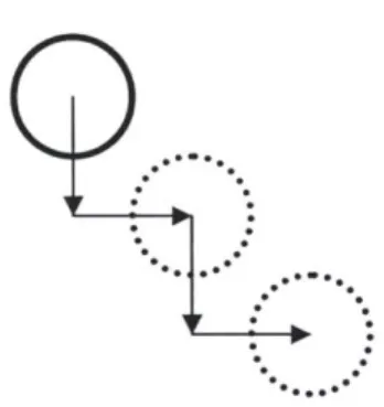
Figure 3.9: "Manhattan" motion between points...29
Figure 3.10: Sweeping to a desired point from an unknown origin. ... 29
Figure 3.12: Magnetic field interactions between electromagnets. The top images show magnetic flux lines and the bottom images map flux density to brightness. The three image pairs show the fields resulting from a single center magnet turned on (left), the left and center magnets turned on (center), and all three magnets turned on (right). The effect of this field-shifting behavior can be modeled approximately using force summation. These images were generated with the VisiMag
softw are package [5] ... 31
Figure 3.13: Four electromagnets with different duty cycles combine to produce a force with a new direction and m agnitude... 33
Figure 3.14: Anti-aliasing methods. The squares represent magnet cells, and intensity of each shad-ed square corresponds to the duty cycle of the magnet. The "dot" technique (left) results in slower travel than the "jet" technique (right). ... 33
Figure 3.15: "Dot" and "Jet" equivalents in computer graphics. The three dots use different falloff m etrics...34
Figure 3.16: "Dot" force field (left) versus "Jet" force field (right)...34
Figure 4.1: Translate and rotate/zoom operations. The puck that the user is holding has been locked to a particular m ap location. ... 37
Figure 4.2: Two actuated tangible workbenches running a distributed application for cellphone tower placement. The tables maintain a synchronized state over an Internet connection. Translu-cent hand silhouettes show remote user activity...38
Figure 4.3: Collar and ring constraint jigs. ... 41
Figure 4.4: An inconsistent set of constraints... 43
Figure 4.5: Hands and jigs and their projected silhouettes...44
Figure C. 1: Data flow diagram showing one iteration of the Actuated Workbench control lo op ... 5 6 Figure D. 1: Comparison of degrees of control in various actuation systems...58
Chapter 1
Introduction
1.1 Tangible User Interfaces
For most of the history of computing, the primary means of representing digital informa-tion has been screen-based text and graphics. The WIMP (Windows, Icons, Menus, and Pointer) interface metaphor, which grew out of the computational capabilities available in the late 1970's, has become highly pervasive. Although it represents a vast improvement over the batch processing and command line interfaces found in the earliest days of com-puting, it is unlikely to meet the demanding user interface needs of modem, real-time, high-performance applications. The WIMP paradigm has an inherent asymmetry between input and output: while it uses millions of pixels of graphical output, it uses a single cur-sor-driven point input, with no physical or kinesthetic affordances and no way to engage multiple users, multiple hands, or multiple senses. It is a predominantly visual paradigm that does not take advantage of the natural abilities humans have developed through a life-time of interaction with the physical world.
The limitations of graphical user interfaces have resulted in many new branches of research that expand our vision of human-computer interaction beyond the limited modes available via a traditional keyboard and mouse. The new research areas of virtual reality, wearable computing, ubiquitous computing, and augmented reality take advantage of new input and output technologies such as large, high-resolution displays, high fidelity audio, haptic feedback devices, voice and gesture input, and pen computing.
Of particular relevance to this thesis is a type of interface that attempts to bridge the
gap between cyberspace and the physical world by giving physical form to digital infor-mation. These "graspable" [18] or "tangible" [23] user interfaces use physical objects to
represent both digital information and computational operations, shifting computation from the onscreen desktop to our bodies and the physical spaces we inhabit. The tangible user interface (TUI) makes use of natural physical affordances to achieve a more seamless interaction between people and information. TUIs allow two-handed manipulation,
sim-plify collocated multi-user collaboration, offer kinesthetic memory cues, leverage existing
physical skills and work practices, and take advantage of our natural ability to spatially organize objects to solve problems.
1.2 Interactive Workbenches
Recently, many tangible user interfaces have adopted a "workbench" metaphor, in which the user manipulates tracked objects on an interactive surface. The desktops, walls, and windows of an architectural space are thereby transformed into active interfaces between the physical and virtual worlds. A computer senses the positions and states of the graspable objects on the surfaces and responds to users' physical input with graphical out-put, projected on and around the objects on the table. These interfaces have been used for a wide variety of applications, from musical performance [40] to video logging [12]. Sys-tems such as the DigitalDesk [53], Bricks [17], Sensetable [39], and Urp [51] offer many advantages over purely graphical interfaces, including the ability for users to organize objects spatially to aid problem solving, the potential for two-handed interaction, and ease of collaboration between multiple collocated users.
However, current interactive workbench systems share a common weakness. While input occurs through the physical manipulation of tangible objects, output is displayed only through sound or graphical projection on and around the objects. As a result, the objects can feel like loosely coupled handles to digital information rather than physical manifestations of the information itself.
In addition, the user must sometimes compensate for inconsistencies when links between the digital data and the physical objects are broken. Such broken links can arise when a change occurs in the computer model that is not reflected in a physical change of its associated object. With the computer system unable to move the objects on the table surface, it cannot undo physical input, correct physical inconsistencies in the layouts of the objects, or guide the user in the physical manipulation of the objects. In short, the physical interaction between human and computer remains one-sided.
VIDEO _d PROJECTION OMMPUTERO - ACTUATIONCOPTTN MANIPULATION POSITION SENSING
Figure 1.1: Traditional interactive workbench systems provide feedback through video projection alone. The Actuated Workbench adds an addi-tional feedback loop using physical movement of the tracked objects.
1.3 Inconsistencies in Tangible Interfaces
Inconsistencies can occur in various types of interactions:
- Remote Collaboration. When there are multiple instantiations of a work table on
which physical objects represent digital information, the physical state of each table can become inconsistent whenever a user moves objects on one table, but the remote user does not move the corresponding objects on the other table. Though the graphical projections
can be synchronized, the discrepancies between the physical positions of objects on the tables will remain.
- Simulation. A software simulation running in real-time may compute that the value associated with an object on the table has changed. The object's position or orientation may be inconsistent with the new value of its corresponding software parameter.
- Constraints. An application may have constraints on the spatial arrangement of
objects on the table, such as zoning laws in an urban planning application. If the user moves an object to the wrong part of the table, some of these constraints may be violated. Existing systems can provide graphical feedback to inform the user that a constraint has been violated, but cannot fix the problem in both the digital and physical representations.
- Navigation. In an application with navigation features, such as one that uses a map
[49], it is useful to rotate, translate or scale the map by moving the physical objects on top of it. However, if there are several physical objects representing fixed landmarks on the map, their positions on the table will no longer be correct once the underlying map is moved.
1.4 Preventing Inconsistency
There are several design approaches to dealing with the problem of inconsistency. One is to structure the interaction so that the physical objects can never become inconsistent with their digital counterparts. For example, in the Urp system [51], the user moves build-ing models around on the tabletop, and the system displays graphical information in response. In this case the software has no control over the position or orientation of the buildings, so building placement cannot cause inconsistency. For some applications this approach works well, but it tends to limit the system's practicality in real-world situations.
Another approach to inconsistency is to use abstract physical objects, rely-ing on graphics to represent system state. An example of this technique would be to represent the position of a dial with a plain circular "puck" and a projected arrow (Figure 1.2), rather
than an arrow that is physically part of Figure 1.2: Addressing the nulling problem.
the puck. In this way the system can
rotate the arrow independently of the physical puck if necessary. If the arrow were physi-cally part of the puck, the user would have to set it to the correct position associated with the digital value of the parameter, a difficulty Buxton has referred to as "the nulling prob-lem" [9]. This use of abstract objects for input works well for dealing with the rotation of pucks, but it cannot be applied to cases where the pucks must be translated.
Yet another approach is to provide graphical feedback to alert the user when an incon-sistency arises. A projected graphical "shadow" of an object can represent that the physi-cal object is not where the computer thinks it should be. The computer can then ignore the physical object until the user has "reattached" it to its shadow. In practice, this method can break the flow of interaction with the system and confuse users. It runs contrary to the design goal that the objects should be embodiments of digital information rather than just handles attached to that information.
1.5 Research Approach and Thesis Overview
By adding computer-controlled actuation to tabletop tangible interfaces, we provided
new solutions to many of these inconsistency problems. We designed and built a system called the Actuated Workbench, a hardware and software infrastructure enabling a
com-puter to smoothly move objects on a table surface in two dimensions. This thesis describes the underlying technology of the Actuated Workbench and discusses the hardware and software design decisions involved in its construction. It then introduces a variety of tech-niques newly enabled by actuation and explains how they can improve upon tangible
Chapter 2
Background and Related Work
2.1 Interactive Surfaces
Interactive surfaces are a common variety of TUI in which physical objects are manipu-lated by users on an augmented planar surface. The presence, identity, and configuration of these objects are electronically tracked, and the computer interprets and processes this information to provide graphical feedback. The two primary varieties of interactive sur-faces are (1) interactive workbenches, which use a horizontal work surface; and (2) inter-active walls, which use a vertical work surface to which objects are affixed using magnets, sticky notes, or thumbtacks.
This thesis focuses on interactive workbench systems, of which there are many examples. One of the earliest such systems was the DigitalDesk
[53], which supported augmented interaction with paper documents on a physical desktop. The paper
documents were identified with overhead cameras, Figure 2.1: Digital Desk (calculator application) and information was projected around them
(Fig-ure 2.1).
Bricks [17] was another early workbench system, in which users placed multiple bricks onto various
/
MEMO* screen-based virtual objects. The bricks were trackedwith six degrees of freedom, and could be used to Figure 2.3: Conceptual sketch
of Bricks system. physically rotate, translate, scale, and deform the vir-tual entities to which they were attached (Figure 2.3). In the "GraspDraw" application
(Figure 2.2), bricks could also be bound to tools and attributes, making them operators rather than handles.
Figure 2.2: The GraspDraw application (left) used a tool palette and inkwell (right). The metaDESK system [49], shown in Figure 2.4,
supported interaction with a geographical space through the manipulation of physical tokens described as physical icons or "phicons." This system was lim-ited in that it used highly representational tokens that
Figure 2.4: The metaDESK
were permanently bound to their geographical "con- system used physical icons and lenses to navigate and tents," without mechanisms for rebinding, explore geographical spaces.
Another workbench approach was the "Real Reality" system for assembly line planning in industrial contexts [44]. The system used a novel
Figure 2.5: The "Real Reality" system grasp-tracking approach to manipulate literal
for assembly line planning. physical models of the assembly line in conjunc-tion with physical representaconjunc-tions of logical flows (Figure 2.5).
The BUILD-IT platform [19] used a special workbench layout that facilitated the
binding of brick elements to data and func- 5,\
Figure 2.6: The BUILD-IT system for floor planning combined 2D and 3D views.
tional elements (Figure 2.6). It was used to create and test an application for floor planning that combined 2D and 3D views.
The Urp urban planning system [51] was one of the most fully developed interactive workbench systems. Combining physical building models with projected graphical simulations, it supported shadow studies, reflection studies, wind simulations, zoning metrics, and
Figure 2.7: Urp, a tangible
many other features useful for making urban planning workbench for urban planning. decisions.
Interactive workbench systems have also been applied to more abstract problem domains for which inherently geometrical representations do not exist. For example,
Figure 2.8: The Sensetable platform has the Sensetable system has been used for
been used for supply chain visualization
(left) and musical performance (right), supply chain visualization [39] and musi-cal performance [40].
2.2 Two-Dimensional Actuation Technologies
The computer-controlled configuration of objects on a flat surface has been studied in both the HCI domain and in the realm of industrial mechanics. Some early systems such as Seek [37] used robotic arms to arrange parts or objects on a table. Though an effective and dexterous method for computer control, the use of robotic arms would likely be distracting for interactive workbench systems. Moreover, it would be complicated and expensive to implement the multiple arms required to move multiple objects simultaneously. Recently, researchers in HCI and robotics have developed systems attempting to move objects
with-out the use of robotic arms. We examine some of these for their applicability to interactive workbench systems.
The PsyBench [7] prototype was built using parts from a computerized chess set that moved magnetic pieces using an electromagnet mounted on an x-y plotter under the table. This allowed the position of objects in the two workspaces to be synchronized. Though similar to the Actuated Workbench in its use of magnetism to grab objects, the PsyBench prototype had a variety of implementation limitations. It was only capable of inaccurate, teetering movements of the objects, and it was limited to straight-line motion. Further-more, it was unable to control the orientation of the moving objects, and it could only move one object at a time.
Some recent robotics research targets actuation problems such as part feeding in facto-ries, parcel sorting in distribution warehouses, and luggage sorting in airports. The Uni-versal Planar Manipulator (UPM) [42] uses the horizontal vibration of a flat surface to move multiple objects at a time. Complex movements of specific objects on the surface are achieved using interference patterns of the vibration waves as they propagate across the surface. This system presents an effective way to manipulate many small parts without the need for motors or magnets, and its designers successfully used it in a closed-loop vision-tracking system. However, several aspects of the UPM's design detract from its usefulness in interactive workbench interfaces. First, in its present state, it is only capable of slow object translations and rotations; feed rates are on the order of millimeters per sec-ond. Second, the mechanism for vibrating the surface occupies space around the edges, preventing the easy tiling of multiple surfaces. Third, the system is noisy due to the mech-anism needed to vibrate the flat surface and the sound of the vibrating objects. While not a problem in a factory assembly-line setting, this noise might be distracting for HCI.
Another system, the Modular Distributed Manipulator System (MDMS) [29] consists of an array of orthogonally oriented wheels that support and move objects through com-bined vector forces created by the rotating wheels. This actuation method presents a clever solution to the problem of friction: instead of dragging or sliding objects, they are rolled along the tops of the wheels. Like the Actuated Workbench, the MDMS is scalable to larger areas, requiring only that more actuators be set up next to the existing array. The MDMS differs from our work in that it is intended for manipulating large parcels, factory materials, or pieces of luggage in a conveyor belt type situation. Moreover, the surface upon which the objects rest is neither flat nor continuous (because it is made up of many small wheels), making it unsuitable for the projection often used in interactive workbench interfaces.
2.3 Haptic and Force Feedback Interfaces
Researchers in the field of haptics have devised many ways of employing the sense of touch in computer interfaces. Haptic feedback devices fall into two general categories: forcefeedback devices that interact with human muscles and tendons to give the sensation of a force being applied, and tactilefeedback devices that interact with the nerve endings of the skin to indicate heat, pressure, or texture.
The most common application of haptic feedback devices is to provide touch stimuli to virtual reality environments, allowing computers to simulate the feel of a virtual object, but studies have also shown that augmenting any visual system with haptic feedback can prove useful. By adding an additional information channel to a visual interface, haptic feedback can increase the amount of information that is simultaneously processed by the brain. This extra information can reduce error, lower energy consumption, and accelerate task completion [45][46]. In addition, this extra information can compensate for ambigu-ities or errors in the visual information, making a visual display with haptic feedback
per-form more effectively than a stereoscopic display or a display with multiple viewpoints
[8]. An experiment by Batter and Brooks suggests that haptic interfaces are effective
edu-cational aids; in their experiment, physics students who explored electrostatic fields using a touch interface developed a better understanding than students without access to haptic devices in their lab work [4].
A wide variety of haptic feedback technologies have been developed, some of which
are commercially available. The most common devices are standard input devices such as joysticks, mice [21], or steering wheels, augmented with motors or vibrators to provide touch or force feedback along one or two dimensions. More complicated devices, such as the PHANToM [33] and the HapticMaster [16], provide complex three-dimensional force control through robotic arm joints or magnetic levitation [6]. Other devices, like the CyberGrasp [52], are attached to the arm or hand as an robotic exoskeleton. The FEELEX system [22] can simulate texture and the contour of a landscape using an array of linear actuators.
2.4 Kinesthesia, Proprioception, Memory, and Perceptual Psychology
A large body of psychology work examines the ways in which humans use the spatialarrangement of objects to aid in problem solving. Kirsh showed that people frequently manipulate their environment to enhance memory or simplify their choices [26][27]. For example, people often sort a large group of objects into smaller groups to help them remember which objects share similar properties. A study by Zhang [54] demonstrated that the kind of objects used in a problem-solving task can dramatically effect how people think about a task and how long the task takes to solve. He compared the time required to solve a puzzle using two types of physical objects, and found that objects which afforded stacking allowed people to complete the task in half the time and with substantially fewer errors. Patten presented a study [38] in which participants using a tangible interface to
organize news articles performed better at location recall than participants using a graphi-cal interface, often using the spatial relationship between physigraphi-cal objects and parts of the environment to help them remember the content of the physical objects.
There is also a variety of work on how people encode and use spatial information about their environment. A study by Malone [31] suggested that office workers with more sophis-ticated organizational schemes were better at locating their documents. However, formal experiments on this question suggest that it may be difficult to rely on spatial organization alone for recall. For example, Dumas and Jones found that retrieving documents by name was more effective than using spatial information for retrieval [13], and Lansdale argues that memory of location can be quite poor in cases where documents are not organized according to some logical structure. In cases where a structure is imposed, however, sub-jects can use it to help determine the location of documents, resulting in better recall [28].
Other studies have attempted to determine the extent to which spatial information is automatically encoded in the absence of a particular organizational scheme. Mandler et al. concluded that a great deal of object location information is encoded automatically, after a study showing only a small decrease in recall performance when subjects were not told to remember object location [32]. However, work by Naveh-Benjamin [36] suggested that this location information is encoded automatically only when subjects modify a spatial configuration of objects, and not when they simply observe such a configuration. A study
by Tan et al. showed that using a touchscreen rather than a mouse results in better
perfor-mance on a spatial recall task, confirming that kinesthetic cues are an important compo-nent of spatial memory encoding [48]. Despite disagreements in the literature as to the process of spatial memory encoding, it remains clear that spacial memory can be reliably used in practice to improve task performance. An evaluation of the Data Mountain system
by Robertson et al. demonstrated an effective application of spatial memory to a task
Chapter 3
Hardware and Software Design
3.1 Design ParametersThe Actuated Workbench's design reflects several concerns of compatibility with current interactive workbench systems. First, the tagging and tracking technologies in these inter-faces have begun to decrease in size, allowing the objects or "pucks" that hold them to be quite small. Zowie/LEGO demonstrated an example of such technology in a toy [20] which tracked objects with passive tags only 1.5cm in diameter and 2mm in height. While we considered designing motorized pucks that drive themselves around the tabletop on wheels, we felt these would tend to be relatively large compared to the tags. Motorized pucks would also require batteries that might need to be changed or recharged frequently due to the motors' power requirements. Since many tagging technologies used today are passive devices, we sought to keep the actuation technology passive as well.
A key interaction technique in most
interac-tive workbench interfaces is the ability to manipulate multiple objects at the same time using both hands. Therefore, we wanted the computer actuation technology to be able to move multiple objects at the
Figure 3.1: Our basic actuation platform same time, preferably recreating users' ges-contains a grid of 64 computer-controlled tures with the objects. We also wanted the
electromagnets.
actuation system to be scalable to accom-modate a variety of sensing areas. Finally, our ideal system would be silent, so as not to unintentionally distract the user when an object is moved on the surface.
3.2 Mechanical Design
Our basic actuation system consists of a
16.5cm fixed array of 64 electromagnets
*
arranged in an 8 x 8 grid under a layer of0.63cm acrylic (Figure 3.1). Though this provides only a limited area for actuation, we tile these arrays together to create
larger actuation surfaces, the only limita- Figure 3.2: Overhead view of
tions on scalability being the complexity electromagnet array.
of electronically addressing the arrays, and the power requirements of running such a large number of electromagnets. We built the system using custom made electromagnets, each measuring 1.9cm in diameter and 3.8cm in length. They are wound with 32 gauge copper wire with a total length resistance of 120-122 ohms.
Using these custom-wound magnets proved an advantage over most commercially available electromagnets, which are often designed with metal housings intended to focus the magnetic field within a small area around the electromagnet. The uncontained fields of our electromagnets made it easier to
Figure 3.3: Custom- create combinational flux patterns between individual electro-wound electromagnets mantteipracofwihwlbedsuedae.
produce broad, uncon- mantteipracofwihwlbedsuedae.
tamned magnetic fields. Each electromagnet is driven with 27 DC volts and draws about 25OmA. In our current applications, each electromagnet is only active for a few milliseconds at a time, and significant heating of the electromag-nets does not occur. However,, if many electromagelectromag-nets were activated for a long period of time, cooling of the array might be necessary.
3.3 Circuit Design and Hardware-Software Interface
We designed custom electronics to driveeach electromagnet in the array bidirec-tionally, making it possible to set the polarity of each magnet's field, as well as turn individual magnets on and off. Our electronics are designed to set the state of each electromagnet in the array at the
same time. This makes moving multiple Figure 3.4- Custom-fabricated circuit objects simultaneously a simple matter of board containing flip-flops and H-bridge
transistor arrays. setting up separate magnetic fields in
dif-ferent areas of the array. Of course we must take care that these magnetic fields do not overlap, and this consideration limits the number of objects that can be moved simulta-neously.
An Ethernet-equipped microcontroller board, the Systronix SaJe board, natively runs a Java program that receives UDP packets sent via Ethernet from a control computer. It pro-cesses these packets and converts the data for output on two parallel 8-bit data buses. Every 15 microseconds, the microcontroller board clocks each magnet's polarity and enable status (off or on) into a set of octal flip-flops that connect to motor driver chips (containing the H-bridge transistor configuration frequently used for driving electric motors), which then connect to the electromagnets via ribbon cable.
The 15 microsecond refresh rate allows us to vary the strength of each electromagnet's field through pulse-width-modulation (PWM), a common technique for driving electric motors at different speeds by sending them pulses of various duty cycles. We can move objects between individual electromagnets by combining the magnetic fields of several
adjacent electromagnets, each set to a different strength through PWM, so that the object is attracted to a point somewhere in between the electromagnets.
3.4 Puck Design
Though all of the pucks that we use with the system contain permanent magnets, the system is capable of moving any lightweight ferromagnetic object, such as a paperclip or steel bolt. Our acrylic pucks are built to hold powerful 1.1 Tesla neodymium magnets, each 1.26cm x 1.26cm x 0.63cm, in order to provide the strong attractive forces needed to drag the 14g pucks around on the Active Workbench's acrylic surface.
Our initial puck design had dimensions 2.54cm diameter x 2.54cm length. It included a battery, an IR LED for vision tracking, and a switch (to save the battery when not in use). Since the inclu-sion of a battery violated one of our design goals, Figure 3.5: Our initial puck design we later switched to a passive radio frequency tag included a permanent magnet and an for object tracking. This allowed us to use
infrared LED for vision tracking.
slightly smaller and completely passive pucks with an LC tag in place of an LED and battery. Our improved pucks measured 3cm diam-eter x 1.25cm height and held a permanent neodymium magnet and an LC radio frequency tag. Each puck also contained a small momentary pushbutton switch that shorted out the
We attached felt pads to the bottom of each puck, providing the necessary kinetic friction to keep the object from sliding around uncontrollably on the table's surface; bare acrylic-on-acrylic
Figure 3.6: Improved puck design with
is too slippery, resulting in oscillations momentary pushbutton switch (top); exploded view of puck showing permanent as the puck slides past its goal and is maned magnet and LC tag (bottom).LC tag otm then attracted back to it. The 0.63cm
thickness of the felt pad, combined with the 0.63cm bottommost acrylic layer of the puck, results in the permanent magnet being about 1.26cm from the surface of the table, which is itself a piece of 0.63cm acrylic. This positions the permanent magnet about 1.89cm above the tops of the electromagnets. The height of the permanent magnet in the puck has signif-icant effects on the performance of the system, since the neodymium magnet is strong enough to be attracted to the ferrous cores of the underlying electromagnets even when they are not activated. This attraction increases friction on the object, which affects the puck's ability to slide on the surface. We found the amount of friction between the pucks and the table to be a critical element in the system's ability to create smooth 2D motion. In general, we observed that static friction (the friction between the object and the surface when the object is at rest) inhibited smooth motion of the pucks, while kinetic friction facilitated smooth motion by controlling oscillations. After trying a variety of materials, we found that felt on acrylic gave adequate frictional characteristics, but other materials may yield better results in the future.
3.5
Object Tracking and Position Sensing
Electromagnetic radio frequency sensing technology is evolving rapidly to provide robust, low-latency object tracking on table surfaces [20][39]. Though this technology is used
-often in interactive workbench systems, we encountered preliminary difficulties using electromagnetic sensing in conjunction with our magnetic actuation system because of distortions created by the strong magnetic fields of our electromagnets. We eventually overcame this problem through careful calibration of the tracking system, but to avoid these difficulties in the short term, we chose vision tracking for our first system prototype.
Figure 3.7: Overhead view of the Actuated Workbench from vision camera without IR filter (left) and with IR filter (right).
We embedded each puck with a small battery and an infrared LED, and suspended a camera directly above the Actuated Workbench. Adding an infrared filter to the camera blocked out ambient fluorescent light, making the video signal easy to process (Figure
3.7). We used an inexpensive Intel PC Camera Pro USB CCD camera and were able to
achieve a tracking rate of 30 updates per second. This frame rate, though high from a human interaction standpoint, is somewhat slow from a control systems perspective.
Puck tracking was accomplished by detecting bright regions within the image. We used the image histogram to compute a threshold value on startup, and the threshold was used to divide the grayscale image into zeros and ones. We then employed standard blob-analysis techniques [25] to determine the longest horizontal segments. We could track multiple pucks simultaneously in real-time using an association method [3] to distinguish the pucks between frames. In every frame, we associated each observed location with the closest puck location in the previous frame. This association method is not wholly
reli-able, since puck paths that cross each other can interchange identities, but since the perma-nent magnets inside of the pucks tend to repel each other, the pucks rarely get close
enough for this method to break down.
Our final system successfully employed elec-tromagnetic tracking, which proved faster and more robust. The pucks contained pas-sive radio frequency (RF) LC tags, each reso-nant on a unique frequency. We determined the position of each RF tag on the table sur-face using a modified version of the sensing
Electrmanet Array
apparatus found in the ZowieTM playsets [20]. We measured the amplitude of the tag reso-Figure 3.8: Tracking antenna coils nances with several specially shaped anten-and grid of electromagnets. nas. The amplitude of the tag's resonance with each antenna varies as a function of its position on top of the antenna array. This method gives very stable 2D position data accurate to within 2mm. Since each tag on the table resonates at a different frequency, their positions can be determined independently. This eliminates the need for the complex association algorithms required to track multiple objects in a vision-based system, and also provides substantially faster update rates than computer vision. Although the presence of dynamic magnetic fields on the table does cre-ate interference with our electromagnetic tracking system, our software calibrcre-ates for the presence of these magnetic fields, and they do not pose a problem when the system is in use.
3.6 Motion Control and Interpolation
Moving the puck across the table in a linear "Manhattan" fashion (in straight lines at right angles to each other) is a straightforward pro-cess. The puck can be moved to any grid cell on the table by consecutively activating theelec-tromagnets in neighboring cells at full strength, Figure 3.9: "Manhattan" mc as shown in Figure 3.9. Using Manhattan
motion, objects can be moved across the table at rates on the order of 25cm/sec.
Converge on Row Converge on Column
ORIGIN
tion
Fgr.: GRGin
Figure 3.10: Sweeping to a desired point from an unknown origin.
If the board is operating in an "open loop" mode, in which we do not know the current
position of the puck, we can still move it to any point on the table using a sweeping algo-rithm (Figure 3.10). To move the puck to the point (xy) we begin by activating the outer-most rows and then sweeping inward until the target row y is reached. Next, we begin with the outermost columns, and sweep inward in a similar fashion until we reach column x.
This method was useful for moving the puck to the far corners of the table to calibrate the tracking system.
Though Manhattan motion can move the pucks rapidly across the table, it is not very useful for recreating the smooth motions with which a user moves objects on an interac-tive workbench's surface. Since we can control the strength of individual electromagnets through PWM, we can perform a sort of physical anti-aliasing to create smooth travel paths along the table between the discrete positions of the electromagnets. In this section we describe our mathematical model of the Actuated Workbench and present the equa-tions we used in our software to produce smooth motion along arbitrary paths. For a detailed derivation of these equations, refer to Appendix A.
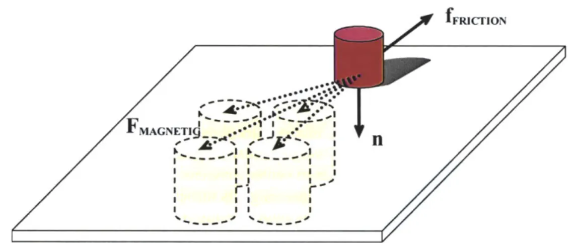
Figure 3.11 is a vector diagram showing our force model. A single puck on the surface of the Actuated Workbench is subject to gravitational force, frictional force, the magnetic forces of attraction between the puck and the activated electromagnets, and the force of attraction between the permanent magnet in the puck and the iron cores of the electromag-nets beneath. fFRICTION MAGNETIQ .. * .* I I I r. I I I I
Figure 3.11: The electromagnets (lower left)
We add these forces to arrive at an equation for the total force on the puck in terms of
fMAG-NET , the total force of magnetic attraction, and fFRICTION-NET , the net friction:
fTOTAL :MAG-NET X + fMAG-NET + fFRICTION-NET (3.1)
axf
FMAG-NET 2 a (3.2)
ifFRICTION-NETII = 9 mg + + IIfMAG-NET 211) (3.3)
zS
Here the puck is positioned at (x, y) and each electromagnet i is positioned at (xi, y )
with duty cycle a. fE and P are constant-magnitude forces of attraction proportional to
the strengths of the electromagnet and the permanent magnet in the puck, zs is the vertical
separation between the puck and the electromagnets, m is the mass of the puck, g is the
acceleration due to gravity, p is a dimensionless coefficient of friction, and i, y, and i are the standard unit vectors.
In reality, the magnetic fields of the activated electromagnets interact in a somewhat more complex manner (Figure 3.12). Nonetheless, the force-summing model just described, in which electromagnets are treated independently of one another, is a reason-able method of approximating the more complicated underlying physics, since the sum-mation of multiple forces due to individual magnets parallels the sumsum-mation of multiple magnetic fields to produce a single force.
Figure 3.12: Magnetic field interactions
between electromagnets. The top images show magnetic flux lines and the bottom images map flux density to brightness. The three
image pairs show the fields resulting from a single center magnet turned on (left), the left and center magnets turned on (center), and all three magnets turned on (right). The effect of this field-shifting behavior can be modeled approximately using force summation. These images were generated with the VisiMag soft-ware package [5].
To produce a puck displacement Ax during a loop interval At, we activate the electro-magnets with duty cycles ai such that
Ax - v0At
fTOTAL 2m At 2 (3.4)
This equation assumes we are keeping track of the puck's instantaneous velocity vo. If
we are using the Actuated Workbench in an "open-loop" mode in which we do not track the instantaneous position or velocity of the puck, we can still compute a reasonable esti-mate of fToTAL using a dead reckoning approach based on assumptions about how the
pre-vious electromagnet settings have affected the position and velocity of our puck according to our force model.
There are many ways in which we could activate the electromagnets so that the result-ing forces summed to the desired value of fTOTAL .In the next section, we describe several different methods for choosing the magnet values.
3.7 Anti-Aliasing Techniques
In computer graphics, the mathematical model of an image is a continuous analog sig-nal that is sampled at discrete points called pixels. Aliasing occurs when the sampling fre-quency is too low for the signal frefre-quency, resulting in a coarse image in which smooth curves are converted to steps and jagged outcrops. The anti-aliasing technique of prefilter-ing combats this problem by treatprefilter-ing each pixel as an area, and computprefilter-ing pixel color based on the overlap of the scene's objects with a pixel's area.
With the Actuated Workbench, we are faced with a
630%
6 o similar problem: we wish to render an analog sig-nal (in this case, a force of a particular direction and magnitude) using a discrete array of cells
100%
10% (variable-duty electromagnets). To do so, we can employ a similar technique: the strength of eachFigure 3.13: Four electromagnets
with different duty cycles combine to electromagnet is determined by the "overlap" of its produce a force with a new direction
and magnitude. magnetic flux lines with the location of the point force. Figure 3.13 shows a configuration in which the forces of four neighboring electro-magnets of different duty cycles combine to create a single force of a new magnitude and direction.
The simplest algorithm for anti-aliasing draws the computer graphics equivalent of a smoothed dot centered at the location of desired travel. Given a desired force vector with head at point (xy), we compute the distance from each electromagnet to (xy), and set its duty cycle in inverse proportion to this distance. As in computer graphics, we can choose any number of falloff metrics. We experimented with Gaussian falloff, but found that in practice it was no better than a simple linear falloff metric.
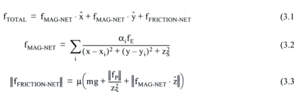
Figure 3.14: Anti-aliasing
methods. The squares repre-sent magnet cells, and intensity of each shaded square corresponds to the duty cycle of the magnet. The "dot" technique (left) results in slower travel than the "jet" technique (right).
A drawback of the dot-based method is that it limits the puck's top speed of travel to
must be positioned close to the puck, and the forces produced by some of the activated electromagnets will pull the puck backwards against the desired direction of travel (Figure 3.14).
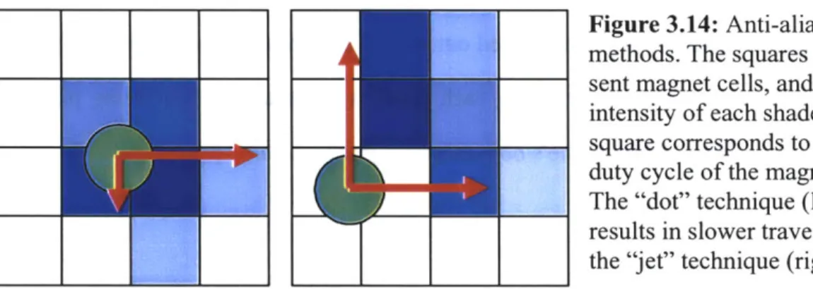
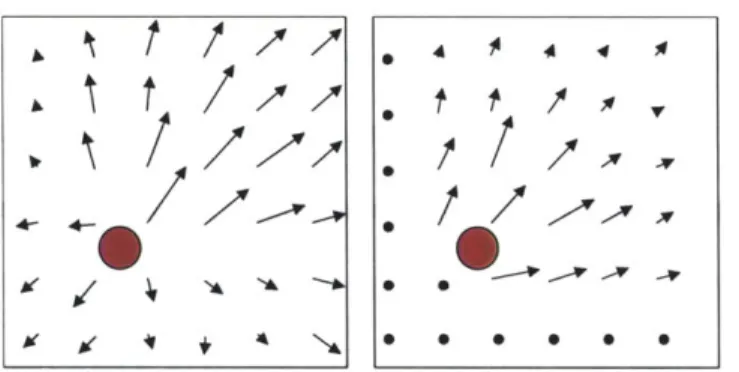
If we know the position of the puck and the
direction of travel that we hope to produce, we can
pull the puck using only the electromagnets located DOT PATTERNS in this direction relative to the puck. To do so, we
first compute the vector from each electromagnet to
the target (xy), and then compute the scalar projec- JET PATTERN
Figure 3.15: "Dot" and "Jet"
tion of this vector onto the direction-of-travel vec- equivalents in computer graphics. The three dots use different falloff tor. Taking the set of vectors of positive magnitude metrics.
produces a collection of forces resembling a 'jet" in
fluid mechanics (Figure 3.16). Jet-based movement can move pucks across the table almost as fast as Manhattan motion.
Figure 3.16: "Dot" force
field (left) versus "Jet" force field (right).Chapter 4
Applications
4.1 Types of Applications
Having developed a system meeting our design criteria for an interactive workbench actu-ation system, we began to imagine the new interaction techniques and applicactu-ations that our system could support. This chapter begins by describing extensions of basic GUI func-tions into the physical domain, and then goes on to describe higher level applicafunc-tions, including some solutions to classic problems in interactive workbench interfaces. We built prototypes of many of these applications; other application ideas would require further development of the Actuated Workbench to address its limitations in speed, magnetic strength, scale, and resolution.
4.2 Extending GUI Functions to the Physical Domain
- Search and retrieve. As the number of pucks increases in an interactive workbench
system, it becomes more difficult for a user to keep track of every item on the table, just as it is difficult to keep track of many graphical icons on a computer desktop. A search and retrieve function could respond to a user query by finding matching items and either mov-ing them to another place on the tabletop or wigglmov-ing them to get the user's attention. Note that the Actuated Workbench would assist only in displaying the results of search queries; the input of the query expression would require a separate interface, such as Ullmer's token-based tangible query interface [50].
- Sort. A more powerful function would be one in which the computer could
physi-cally sort and arrange pucks on the table according to user-specified parameters. This could help the user organize a large number of data items before manually interacting with them.
- History and Undo. As a user makes changes to data through physical input, she may
wish to undo some changes. A physical undo in this system could move the pucks back to their positions before the last change. It could also show the user the exact sequence of movements she had performed. In this sense, both "undo" and "rewind" commands are possible..
- Teaching and Guiding. Because the Actuated Workbench gives the computer the
ability to recreate users' gestures with the pucks, it becomes possible for the computer to teach the user something about interacting with the system through physical gestures. If
specific gestures are used in the interface to trigger certain commands (such as a shaking gesture to unbind a puck from a data item), the computer can show a novice or a forgetful user how to make that gesture with the puck. This way, many of an application designer's commands can be taught to users without the need for intensive human coaching. In addi-tion, if a user is uncertain how to proceed while using a problem-solving or simulation system, the computer could suggest a physical configuration of the pucks.
4.3 Navigation
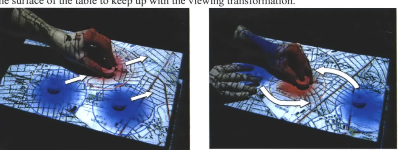
In an overhead map browsing interface such as metaDESK [49], it is often useful to rotate, translate, or scale the map. However, if there are physical objects on the map sur-face that correspond to map landmarks, their positions on the table will no longer be cor-rect once the underlying map is moved. We built a map browsing interface that allows users to navigate around a map by moving physical objects and automatically corrects the positions of physical objects on the map surface using actuation.
Pushing the button on a puck locks down the position of its corresponding map land-mark. The user can then move the puck to scroll the overhead map. Users can rotate or zoom the map using a two-handed technique; first a landmark is locked down, and then
another landmark is moved to specify a scaling and rotation transformation. Since these transformation operations change the position of each landmark on the table, actuation is necessary to preserve consistency between the physical and digital states of the system. As the user scrolls, rotates, or zooms the graphical display, the pucks automatically move on the surface of the table to keep up with the viewing transformation.
Figure 4.1: Translate and rotate/zoom operations. The puck that the
user is holding has been locked to a particular map location.
4.4 Remote Synchronization
One advantage that interactive workbench interfaces offer is the ease with which multiple users can make simultaneous changes to the system. Users can observe each other's changes, and any user can reach out and physically change the shared layout without
hav-ing to grab a mouse or other pointhav-ing device. This is not the case, however, when users are collaborating remotely. In this scenario, a mechanism for physical actuation of the pucks becomes valuable for synchronizing multiple physically separated workbench stations. Without such a mechanism, real-time physical synchronization of the two tables would not be possible, and inconsistencies could arise between the graphical projection and the
phys-ical state of the pucks on the table.
One example of a system that could benefit from physical synchronization is Urp [51]. In the Urp system, users manipulate physical models of buildings on a table and the
com-puter displays simulation information in the form of projected "digital shadows" around the buildings. "Distributed Urp" (Durp) later attempted to create distributed workspaces between multiple remote users. Identical Urp systems were set up in two separate loca-tions, and the two systems were synchronized through identical graphical projections onto the workbench. However, if a user in one location moved a building, only the "digital shadow" of the building, and not the physical model, would move in the remote location. In addition to facilitating the simple synchronization of these models, the Actuated work-bench could recreate remote users' actual gestures with objects on the table, adding
greatly to the "ghostly presence" [7] sought in remote collaboration interfaces. We built a remote collaboration
demonstration in which two remote tan-gible workbenches are kept synchro-nized. When the motion of a puck is sensed on one table, the remote table uses magnetic actuation to update the position of the corresponding remote
puck, keeping the states of the two
Figure 4.2: Two actuated tangible work-tables the same. If both users simulta- benches running a distributed application for
cellphone tower placement. The tables main-neously attempt to move the same puck, tain a synchronized state over an Internet
connection. Translucent hand silhouettes each user will feel a force pulling show remote user activity.
against the puck, indicating the
direc-tion in which the remote user is attempting the move the object. In this situadirec-tion, the puck becomes a conduit for interpersonal haptic communication. Actuation can therefore serve two purposes during remote collaboration: (1) synchronizing a shared workspace; and (2) providing a haptic communication link.
r-4.5 Scientific Visualization
The Actuated Workbench could be helpful in the scientific visualization of complex mechanical systems. For example, a solar system model in the manner of an orrery could be created on an interactive interface with full actuation of the planetary orbits. The user could change the physical properties of the planets or teach the computer new orbital paths, and then watch the resulting motions of the planets.
Similarly, the Actuated Workbench could be used to teach students about physics by demonstrating the attraction and repulsion of charged particles represented by pucks on the table. As a student moved the pucks around on the table, the system could make them rush together or fly apart to illustrate forces between the objects.
4.6 Entertainment
In addition to these more practical applications, the Actuated Workbench could be used to add a physical dimension to computer entertainment. Though motorized chess sets have existed for many years, they operate using a single electromagnet mounted on an x-y plotter mechanism, limiting them to moving one object at a time. The Actuated Work-bench could provide a significant improvement to these devices, making them more flexi-ble for a variety of games. Classic computer games like Pong [2] could now be played using a physical puck and two physical paddles manipulated by the users. Distributed Pong could be played with a local user moving one paddle and the computer moving a remote user's paddle on the table. In addition, the Actuated Workbench can be used to flip over thin, polarized magnetic pucks by rapidly reversing the polarity of the electromag-nets. This could be used to play a physical game of Reversi with the computer. Finally, one could create painting or drawing programs in which a pen or brush was attached to the puck. Various plotter-based computer-controlled drawing systems have been developed
or sharing control between the computer and the user. The computer's movement of the puck could be used to teach certain artistic gestures or handwriting movements.
4.7 Specifying and Maintaining Constraints
Tabletop tangible interfaces are well suited to spatial layout of items in an application con-taining layout constraints. Examples of such constraints can be found in urban planning
[51], circuit routing, and task scheduling [24]. Some of these constraints can be easily
expressed as mathematical formulae, e.g. "two buildings may never be less than 20 meters apart." Making the computer responsible for monitoring these constraints frees the user to focus on the more salient aspects of the task at hand, instead of constantly having to check whether a proposed design violates any constraints.
We built a constraint solving system that supports both programmatic and physical constraints. Programmatic constraints are more appropriate for constraints that can be easy expressed mathematically, and do not change often in an application. Physical constraints are more appropriate for situations where a user would like to experiment with a constraint briefly, modify a constraint over time, or add new constraints as their design evolves. A physical constraint can simply be a user's hand on the table, holding a puck in place or preventing it from moving to a certain part of the table. A physical constraint may also be a physical "jig" placed around one or more pucks. We have used several types of jigs to represent common constraints:
- A "collar" can be placed around a puck to
con-strain its proximity to other pucks. This collar is sim- Q
ply a circular disk of plastic that bumps into other
pucks to keep them a minimum distance away. The collar can be flipped over to raise the height of the plastic disc above the table. In this case, other pucks with raised collars will be kept farther away then those with lowered collars or no collars. In this way,
Figure 4.3: Collar and ring
minimum distance constraints can be applied selec- constraint jigs. tively to different pucks.
- A "ring" can ensure that pucks remain within a certain distance of each other. This
constraint is an oval shaped piece of plastic that surrounds two or more pucks.
- Finally, a nonmagnetic object can be placed on the table and used to ensure that
cer-tain pucks stay inside or outside of a particular region on the board.
When developing software to support constraints with our actuation mechanism, we began by incorporating the GUI constraint solver Cassowary [1]. However, it was difficult to implement some parts of our system using Cassowary for two reasons. The first was Cassowary's method of dealing with conflicting constraints: Cassowary will fully satisfy a higher priority constraint at the expense of a lower priority one. While this approach makes sense for problems like window placement in a GUI, it is not appropriate for many types of constraints on a TUI platform. In our actuated system, the constraint solver is run each time the system receives new data about the position of the pucks. With the Cas-sowary-style solution, slight differences in puck positions can lead to large discontinuities in the solution to the constraints. These discontinuities can cause pucks on the table to seem unresponsive to changes the user is making, and then suddenly fly across the table