HAL Id: hal-02570467
https://hal.archives-ouvertes.fr/hal-02570467
Submitted on 12 May 2020HAL is a multi-disciplinary open access archive for the deposit and dissemination of sci-entific research documents, whether they are pub-lished or not. The documents may come from teaching and research institutions in France or abroad, or from public or private research centers.
L’archive ouverte pluridisciplinaire HAL, est destinée au dépôt et à la diffusion de documents scientifiques de niveau recherche, publiés ou non, émanant des établissements d’enseignement et de recherche français ou étrangers, des laboratoires publics ou privés.
Recent severe accident research synthesis of the major
outcomes from the SARNET network
J.-P. van Dorsselaere, A. Auvinen, D. Beraha, P. Chatelard, L.E. Herranz, C.
Journeau, W. Klein-Hessling, I. Kljenak, A. Miassoedov, S. Paci, et al.
To cite this version:
J.-P. van Dorsselaere, A. Auvinen, D. Beraha, P. Chatelard, L.E. Herranz, et al.. Recent severe accident research synthesis of the major outcomes from the SARNET network. Nuclear Engineering and Design, Elsevier, 2015, 291, pp.19-34. �10.1016/j.nucengdes.2015.03.022�. �hal-02570467�
Recent severe accident research
Synthesis of the major outcomes from the SARNET network
J.-P. Van Dorsselaere1, A. Auvinen2, D. Beraha3, P. Chatelard1, L.E. Herranz4, C. Journeau5,
W. Klein-Hessling3, I. Kljenak6, A. Miassoedov7, S. Paci8, R. Zeyen9
1Institut de Radioprotection et de Sûreté Nucléaire (IRSN), France 2 VTT Technical Research Centre, Finland
3Gesellschaft für Anlagen- und Reaktorsicherheit mbH (GRS), Germany
4Centro de Investigaciones Energéticas MedioAmbientales y Tecnológicas (CIEMAT), Spain 5Commissariat à l’Energie Atomique et aux Energies Alternatives (CEA), France
6Jozef Stefan Institute (JSI), Slovenia 7 Karlsruhe Institute of Technology (KIT), Germany
8University of Pisa, Italy
9European Commission Joint Research Centre, Institute for Energy (JRC/IET), The Netherlands * Corresponding author: Postal address Cadarache, BP 3 - 13115 Saint-Paul-Lez-Durance, Cedex, France, Tel. (+33) 442199709, Fax (+33) 442199156, Email: jean-pierre.van-dorsselaere@irsn.fr
Abstract
The SARNET network (Severe Accident Research NETwork of excellence), co-funded by the European Commission from 2004 to 2013, has allowed to significantly improve the knowledge on severe accidents and to disseminate it through courses and ERMSAR conferences. The major investigated topics, involving more than 250 researchers from 22 countries, were in- and ex-vessel corium/debris coolability, molten-core-concrete-interaction, steam explosion, hydrogen combustion and mitigation in containment, impact of oxidising conditions on source term, and iodine chemistry. The ranking of the high priority issues was updated to account for the results of recent international research and for the impact of Fukushima nuclear accidents in Japan. In addition, the ASTEC integral code was further developed to capitalize the new knowledge. The network has reached self-sustainability by integration in mid-2013 into the NUGENIA Association. The main activities and outcomes of the network are presented.
1. INTRODUCTION
Despite accident prevention measures adopted in nuclear power plants (NPP), some accidents, in circumstances of very low probability, may develop into severe accidents with core melting and plant damage and lead to dispersal of radioactive materials into the environment, thus constituting a hazard for the public health and for the environment. According to [1], the application of severe accident management (SAM) and mitigation measures could lead to achieve a frequency of occurrence of severe core damage below 10–5 events per plant operating year
(this figure and the reference have not been updated after Fukuhima-Daiichi events in 2011). Research on severe accidents started mainly in the sixties and seventies with risk assessment studies and later on with experimental programs, development of numerical simulation codes and of Level 2 Probabilistic Safety Assessments (PSA2). A huge amount of research and development (R&D) was performed internationally since that period. This was pushed forward by two major accidents: the core melt accident in 1979 in the Three Mile Island Pressurized Water Reactor (PWR) near Harrisburg (Pennsylvania, USA), and the reactivity accident in 1986 in the
Chernobyl RBMK (Water-cooled channel-type reactors with graphite as moderator, designed by Soviet Union) reactor in Ukraine.
Along with the progress of knowledge on severe accident, the national or international funding of R&D was slowly decreasing, and thus, it appeared necessary to better rank the R&D needs, also due to the high complexity of the involved physical phenomena and the high cost of experiments with real materials. In 2004, the European Commission (EC) judged necessary to better coordinate the national efforts in Europe to optimise the use of the available expertise and the experimental facilities in view of resolving the remaining issues for enhancing the safety of existing and future NPPs. This led to launching SARNET ([2] [3]) in the framework of the 6thEC
Framework Programme (FP6), coordinated by IRSN, gathering 55 actors, mostly European ones plus a few out of Europe, on severe accident R&D. One of the main outcomes was the identification of the highest priority severe accident issues still to be solved that helped to build a second phase of the network again supported by EC in the FP7 under the project name ”SARNET2” (www.sar-net.eu) and coordinated by IRSN between April 2009 and March 2013. After the description of the network structure and tasks in Section 2, Section 3 summarizes the main technical outcomes of the following R&D topics: in- and ex-vessel corium/debris coolability, molten-core-concrete-interaction (MCCI), containment issues and source term. Sections 4 and 5 present respectively the activities on the ASTEC IRSN-GRS integral code and on spreading of knowledge. Finally, Section 6 summarizes the ranking of the R&D high-priority issues to be solved, as established at the end of 2013.
2. THE SARNET NETWORK
Forty-three organisations (research organisations, universities, industrial companies, energy utilities, safety authorities and technical safety organizations) from 22 countries participated in the FP7 project, including most key European R&D actors and a few important non-European organizations USNRC (USA), AECL (Canada), KAERI and KINS (Korea) and BARC (India). Japanese organizations JAEA and JNES discussed about joining the network in the future. The overall work, involving about 250 researchers and 30 doctoral students, represented an equivalence of 40 full-time persons per year.
Table 1: List of SARNET2/FP7 partners
Partner Short name Country
Institut de Radioprotection et de Sûreté Nucléaire IRSN France
KFKI Atomic Energy Research Institute AEKI* Hungary
AREVA NP GmbH AREVA GmbH Germany
AREVA NP SAS AREVA NP SAS France
Budapest University of Technology and Economics BME Hungary Commissariat à l'Energie Atomique et aux Energies Alternatives CEA France
Ricerca sul Sistema Energetico - RSE SpA RSE Italy
Chalmers tekniska högskola AB CHALMERS Sweden
Centro de Investigaciones Energeticas MedioAmbientales y
Tecnologicas CIEMAT Spain
National Centre for Scientific Research "DEMOKRITOS" DEMOKRITOS Greece
Electricité de France SA EDF France
Energy Institute JSC Sofia EI Bulgaria
Agenzia Nazionale per le Nuove Tecnologie, l'Energia e lo
Forschungszentrum Jülich GmbH JÜLICH Germany
Karlsruher Institut für Technologie KIT Germany
Gesellschaft für Anlagen- und Reaktorsicherheit mbH GRS Germany National Autonomous Company for Nuclear Activities Nuclear
Research Subsidiary Pitesti INR Romania
Institute for Nuclear Research and Nuclear Energy INRNE Bulgaria Inzinierska Vypoctova Spolocnost Trnava s.r.o. IVS Slovakia
Jozef Stefan Institute JSI Slovenia
Kungl Tekniska Högskolan KTH Sweden
Lithuanian Energy Institute LEI Lithuania
National Nuclear Laboratory NNL UK
Nuclear Research & Consultancy Group v.o.f. NRG The Netherlands
Paul Scherrer Institut PSI Switzerland
Ruhr-Universität Bochum RUB-LEE Germany
Tractebel Engineering SA TRACTEBEL Belgium
Thermodata THERMODATA France
Technical University of Sofia TUS Bulgaria
Urad Jadroveho Dozoru Slovenskej Republiky UJD SR Slovakia
Ustav Jaderneho Vyzkumu Rez a.s. UJV Czech Rep.
University of Newcastle upon Tyne UNEW UK
Dipartimento di Ingegneria Meccanica, Nucleare e della
Produzione - Università di Pisa UNIPI Italy
Universität Stuttgart IKE Germany
NUBIKI Nuclear Safety Research Institute NUBIKI Hungary
VTT Technical Research Centre of Finland VTT Finland
VUJE Trnava, a.s. – Inzinierska, Projektova a Vyskumna
Organizacia VUJE Slovakia
Commission of the European Communities – Joint Research
Centres JRCs EU
Atomic Energy Canada Limited AECL Canada
Korea Atomic Energy Research Institute KAERI Korea
United States Nuclear Regulatory Commission USNRC USA
Korea Institute of Nuclear Safety KINS Korea
Bhabha Atomic Research Centre BARC India
* Now MTA-EK company
The Joint Programme of Activities included three types of activities: joint research activities, integrating activities to strengthen links between the partner organizations, and spreading of excellence and knowledge.
For joint research activities, the ranking of priorities was based on the work done in the EURSAFE FP5 project [4] that elaborated a Phenomena Identification and Ranking Table (PIRT) using two criteria: importance for safety and level of knowledge (taking into account the whole international background). At the end of the SARNET/FP6 project, the update of this process led to select the following R&D issues as highest priority where the remaining uncertainties were judged still too high [5]:
- Core coolability during reflooding and debris cooling in the vessel;
- Ex-vessel melt pool configuration during MCCI, ex-vessel corium coolability by top flooding;
- Melt relocation into water, ex-vessel Fuel Coolant Interaction (FCI); - Hydrogen mixing and combustion in containment;
- Oxidising impact on source term (release of ruthenium in oxidising conditions/air ingress for high burn-up and Mixed OXide (MOX) fuel elements);
- Iodine chemistry in Reactor Coolant System (RCS) and in containment.
The same collaborative method was adopted for all these issues: review and selection of available relevant experiments, contribution to the definition of test matrices, synthesis of the interpretation of past and new experiments, benchmark exercises between numerical simulation codes, review of physical models, proposals of new or improved models to be implemented in simulation codes, in priority ASTEC, and possibly elaboration of state-of-the-art reports (SOAR). Such technical “circles” played an active role in integration by pushing experimentalists and modellers to work closer together. Additional studies were performed in order to bring research results into reactor applications, using various computer codes in order to evaluate the importance of the involved phenomena, in particular through uncertainty studies. Most existing experimental programmes have been taken into account, in particular Phébus FP [6], International Source Term Programme (ISTP) [7], International Scientific and Technical Centre (ISTC) [8] projects and OECD/NEA/CSNI projects. With funding by the SARNET2/FP7 project, new experiments have been performed on debris bed reflooding, molten-core-concrete-interactions, containment thermal-hydraulics and source term.
For integrating activities, knowledge was capitalized into computer codes and databases. For codes, in front of the absence of any reference European integral code, EC pushed toward the capitalization of the whole European severe accident knowledge, based first on the last 15 years research in Europe and secondly on research planned in the two FP6-FP7 projects. The ASTEC code, jointly developed by IRSN and GRS since the end of 90’s [9], was selected for that purpose. Most partners had access to the code and contributed to its enhancement through development and validation of specific models and modules, as well as through extension of the code to all types of European NPPs. ASTEC was an alternative to the MAAP code [10], mainly used by industry worldwide, with a more mechanistic approach in many of the phenomena involved in severe accidents. Its general modelling approach was more similar to the one of the USNRC MELCOR code [11]. For experimental data, the task was to expand the DATANET database [12], built with the EC Joint Research Centre (JRC) STRESA tool, by including all the experimental work carried out during the project.
For spreading of knowledge towards the new generation of researchers and to new countries with nuclear energy generation, the tasks consisted in organization of education courses and conferences, secondments of researchers among SARNET teams, publications in journals and participation in international conferences.
3. MAIN R&D OUTCOMES ON SEVERE ACCIDENTS 3.1 Corium and debris coolability
The main objective was to reduce the remaining uncertainties on the efficiency of cooling degraded reactor core structures and materials (melt mixtures or corium, and debris) during severe accidents so as to limit the progression of the accident. These issues are covered within the scope of SAM for existing reactors and of design and safety evaluations for future reactors. The specific objectives were to create and enhance the experimental database on debris formation, debris and corium coolability in the lower head or in the cavity, and thereby support
the development and validation of models and computer codes for simulation of debris bed and melt pool behaviour. This in turn assists the performance of reactor scale analysis for in-vessel corium coolability and the assessment of the influence of SAM measures on in-vessel coolability, carried out in the reactor application sections of the SARNET work programme.
3.1.1 Formation and cooling of debris beds
One of the conclusions of the OECD 2009 workshop on in-vessel coolability [13] was that substantial knowledge and understanding of governing phenomena concerning coolability of intact rod-like reactor core geometry had been obtained in previous projects [14, 15, 16, 17]. Hence the main experimental and modelling efforts concentrated mainly on the study of formation of debris beds in the process of melt-coolant interaction and their cooling in order to demonstrate effective cooling modes and rates and coolability limits. Although this issue was already studied in the past [18, 19, 20], new experiments aimed at providing more accurate data for the validation of new models which involve 2D/3D resolution of the flow, in contrast with older 1D models. New experiments cover a rather large range of parameters (bed temperature, water flow rate, volumetric power) which goes beyond previously investigated conditions. They investigate also 2D/3D configurations which had been poorly studied.
As an example of these activities, the ability of water injection to remove heat from a strongly overheated core was addressed, typically when degradation is imminent or has already taken place, and ideally to achieve successful quenching. One QUENCH-DEBRIS bundle test was performed at KIT to study the in-core debris bed formation and its coolability by water injection from the bottom (the 10-rod bundle had rods containing pre-fractured ZrO2 segments to simulate
fragments of the fuel pellet inside a Zry-4 cladding). Full oxidation of the top part of the claddings was obtained over a length of 500 mm approximately, after a long phase at a temperature up to 1500°C. During quenching, the claddings were broken, as expected, and a debris bed was formed above the grids located at 350 mm and 1050 mm. The top grid (1350 mm) was not damaged although it was fully oxidized. The debris bed consisted of pre-fragmented zirconia pellets and large pieces of oxidized claddings. An unexpected result of the test was the rather large size (a few cm length) of cladding fragments (smaller sizes were expected, as observed in the TMI-2 accident), which increases the potential of debris bed coolability. The range of particle size in the debris bed was between 2 mm and 2 cm (for cladding shards).
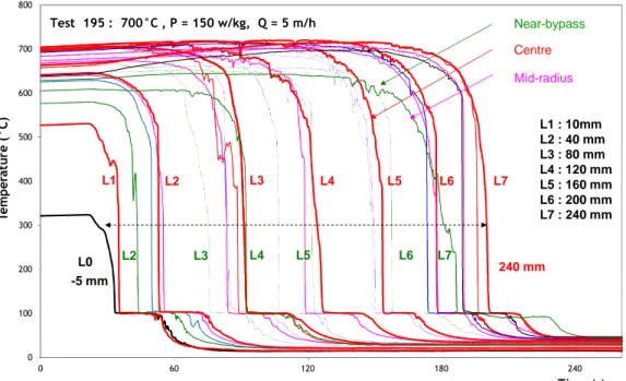
A large part of the experimental investigations on in-vessel debris bed reflooding has been performed in the PRELUDE facility at IRSN [21, 22] (diameter 29 cm and height 25 cm, 5 to 58 kg stainless steel beads 1-4 mm dia., up to 927°C), which has provided a large and systematic database on the effect of injection rate, temperature and debris size on the progression of the water front inside a debris bed. The water and debris temperature measurements allowed the heat fluxes in the different regimes during the reflooding phase to be derived. Hence the quench front propagation in different radial positions of the debris bed was determined (Fig.1). The analysis of those results outlined specific 2D effects during the reflooding with preferential water propagation at the peripheral part of the debris bed where the temperatures are lower due to thermal losses and the porosity larger (the latter is due to the wall boundary effect in the debris bed) [23]. These experiments are an important precursor to the experiments in the larger PEARL facility at IRSN (diameter 50 cm and height 50 cm) that is operational at the end of 2014. One important aspect will be the effect of scale on the water coolability of a particle bed. The scale will have an impact on 2-dimensional effects (because of increased pressure in the bed cause by longer flow path) and will emphasize the effect of residual power (due to the longer time necessary for quenching).
Figure 1: Evolution of the PRELUDE debris bed temperature during the reflooding for different axial levels (from bed bottom) and radial positions
Tests in POMECO (at KTH) and DEBRIS (at IKE) facilities with debris beds addressed the behaviour of realistic debris, i.e. local mixtures with irregularly shaped particles of different sizes (representative of those obtained after corium-water interaction outside of the vessel). Such analyses primarily aimed at consolidating the debris properties results gained from the earlier DEFOR or similar experiments [24]. Both top and bottom flooding were investigated in POMECO and DEBRIS with volumetric induction heating, which required a number of technical innovations to ensure a near-to-uniform temperature profile across the debris bed diameter. DEBRIS analytical tests [25, 26] complement the PEARL experiments by including top and side water injection and considering irregular shape particles (representative of TMI-2 debris), higher pressures and temperatures. In the DEBRIS tests with irregular particle sizes (steel screws 3 mm head diameter x 10 mm length, and steel cylinders 3 x 5.75 mm), the quenching behaviour showed pronounced multi-dimensional features. One important result was that irregularly shaped debris of various sizes can be represented by equivalent mono-sized spheres [27]. Further DEBRIS tests with quenching of hot debris at temperatures up to 1000°C from the top and bottom are foreseen. The new POMECO-FL and -HT facilities were designed and constructed at KTH to perform isothermal and boiling two-phase flow tests with better instrumentation and flexibility to simulate more variable conditions.
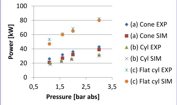
New experiments in the COOLOCE facility at VTT were more directly oriented to coolability of ex-vessel debris beds with complex geometries that are thought to be close to reactor situations: heap-like beds of conical shape with a base diameter of 0.5 m and a height of 0.7 m were used. The conical debris bed is a generic configuration which is also representative a bed made of debris that would have collapsed along a wall because the centre of the cone is a symmetry line which is equivalent to a wall boundary condition. Heap-like beds were observed in the DEFOR experiments and also predicted in plant accident conditions using the DECOSIM code developed at KTH [28]. The main objective of the COOLOCE experiments was to compare the dry-out heat fluxes between a heap-like conical particle bed and an evenly distributed cylindrical one. Because the cylindrical and conical test beds have equal height, the measured dryout power is greater for the conical test bed as a result of lateral flooding through the surface of the cone. Another objective was to provide data for code validation purpose (see the Fig.2 as illustration of comparison between COOLOCE and MEWA IKE code results).
0 100 200 300 400 500 600 700 800 0 60 120 180 240 Te m p er at ur e (° C ) Test 195 : 700°C , P = 150 w/kg, Q = 5 m/h Time (s) Near-bypass Centre Mid-radius -5 mm 240 mm L2 L3 L4 L7 L1 L0 L1 : 10mm L2 : 40 mm L3 : 80 mm L4 : 120 mm L5 : 160 mm L6 : 200 mm L7 : 240 mm L6 L5 L2 L3 L4 L5 L6 L7
Figure 2: MEWA numerical simulation of the dry-out power for conical and cylindrical shapes of a debris bed in the COOLOCE experiments
3.1.2 Coolability of corium in the vessel lower head
Significant investigations of corium and debris coolability in the vessel lower head were performed in the LIVE program at KIT [29]. A very large test matrix has been realised in the LIVE-3D facility, including variation in melt superheat, pouring conditions, external insulation. Particularly the transient and local thermal loads on the vessel wall under different melt pouring patterns were examined. The steady pool behaviour of both homogenous melt pool and two-layer pool configurations was studied. All LIVE-3D experiments provided the melt pool temperature profiles, the axial and radial heat flux distribution through vessel wall, the crust thickness profiles, and the transient behaviour of melt temperature and heat flux. Valuable experimental results such as the temperature of crust and boundary layers were obtained for the modelling and analysis of the characteristics of corium with crust formation. LIVE-2D experiments (using a slice geometry compared to a full hemispherical geometry) were also carried out to compare the results with LIVE-3D experiments under same conditions, which allowed examining the applicability of the results between both geometries, especially the effect of local melt turbulence. The variations of the main parameters included cooling conditions (water cooling of the outer vessel wall from the test beginning or with some delay, water-cooled or insulated lid), power levels during tests, and pouring of the melt in the empty vessel or in the vessel already containing debris.
Tests were performed in the RESCUE-2 facility at CEA to study external cooling limits of a lower head of VVER-440/V213 for in-vessel melt retention and to provide data for code validation. The VVER-440 thermal loads for three possible heat flux profiles, calculated by the ASTEC code, were considered in the tests. One of these profiles simulated a transition from a homogenous pool to a stratified light metal/oxidic melt/heavy metallic melt pool (as seen in the OECD MASCA programme and elsewhere [30, 31]). Differently to the Loviisa configuration, the melt retention concept for standard VVER-440/V213 reactors being operated in the Central Europe is based on a modification of the thermal/biological shield. Water serves as a coolant in a narrow gap between the reactor pressure vessel (RPV) and the insulation.
0
20
40
60
80
100
0,5
1,5
2,5
3,5
Po
w
er
[k
W
]
Pressure [bar abs]
(a) Cone EXP
(a) Cone SIM
(b) Cyl EXP
(b) Cyl SIM
(c) Flat cyl EXP
(c) Flat cyl SIM
KTH researchers developed and applied a coupled thermo-mechanical creep analysis to a BWR lower head geometry with penetrations [32]. The study revealed that, if only control rod guide tube (CRGT) cooling is activated, then (i) the cases with lower melt pool depths (0.7 m and 1.1 m) result in a ballooning type of vessel failure where creep strains are distributed in the lower section of the vessel that is covered by melt pool, and (ii) the cases with higher melt pool depths (1.5 m and 1.9 m) result in a localized creep where the creep strains are concentrated in the vicinity of the uppermost region of the melt pool. Both modes may lead to different melt releases in terms of breach size, melt mass, compositions and superheat. If the external vessel cooling is implemented right before the creep accelerates, then the analysis confirmed the possibility of melt retention by CRGT cooling plus vessel external cooling for all melt pool considered configurations. The failure of the Instrumentation Guide Tube (IGT) penetrations has been also addressed using the same modelling approach [33, 34]. It has been shown that, due to isotropic stretching of the vessel bottom, the IGT pipes can sip out from the vessel if welding of the IGTs to the penetration nozzles fails. However, for the IGTs located at the periphery, the stretching of the vessel is more unidirectional, which leads to potential clamping of the IGTs in the vessel. The analysis also revealed that IGT nozzle weld failure can be expected earlier than vessel failure if the thermal conductivity of solid debris is relatively low. However, if solid debris thermal conductivity is increasing (e.g. due to the large fraction of metal) then failure of the vessel can occur earlier than IGT failure.
Important R&D activities focused on coolability of melt released from a failing RPV and relocating into a water-filled cavity. In particular accident management concepts for BWRs with deep water pools below the vessel were addressed but also shallow pools in existing PWRs were considered, addressing the questions of partial cooling and time delay for MCCI.
3.1.3 Modelling activities and code assessment
The modelling activities (mainly in the ASTEC, ATHLET-CD, MELCOR and SCDAP/RELAP codes) focused mainly on core degradation, melt relocation to the lower plenum, quenching of corium by residual water, re-melting of debris beds and molten pool formation in the lower head during severe accident sequences for different LWR designs. Significant attention was paid to in-vessel coolability issue during different accident stages and specifically to stabilization and localization of a volumetrically heated molten pool in the RPV lower head, with application to vessel external cooling. The last point is in general considered as a main goal of in-vessel accident mitigation strategy.
One of the important activities was the project "Ability of Current Advanced Codes to Predict In-Vessel Core Melt Progression and Degraded Core Coolability", launched by the OECD/NEA/CSNI WGAMA Group. This is a follow-up of the previous OECD benchmark exercise on an alternative TMI-2 accident scenario [35]. The objective of the project was to examine three different severe accident sequences in the frame of a code-to-code benchmark. The impact on hydrogen production, core coolability, corium relocation into the lower plenum and vessel failure was addressed.
3.1.4 Accident behaviour of spent fuel pools
The accident at the Fukushima Dai-ichi Nuclear Power Plant has shown the vulnerability of spent fuel pools (SFP) to the potential loss of sufficient fuel cooling in case of internal events or of extreme external events such as earthquake or flooding. This triggered the production of a new OECD/NEA/CSNI report on the SFP problems (due out in 2015). The SARNET studies have focused on the evaluation of the capabilities, the limitations and the needs for improvement of severe accident codes that are usually used for reactor applications. Five different severe accident codes were used: ASTEC, MELCOR, ATHLET CD, ICARE/CATHARE and RELAP/SCADPSIM. Two main types of scenario were studied; loss of cooling, leading to a gradual uncovering of fuel assemblies, and loss of coolant (water) inducing a fast dewatering of fuel assemblies. Some
studies have also allowed analysing the influence of water injections, as well as of the initial value of the residual power of fuel assemblies.
3.1.5 Synthesis of outcomes on corium/coolability issues
The main achievements for corium and debris coolability and for SFP accidents can be summarised as follows:
Demonstration of possibility of effective cooling of debris beds by penetration of water, even for small diameter debris, although sub-millimetre debris particles prove the most difficult to cool. 2D and 3D effects were highlighted in DEBRIS and PRELUDE facilities. Basic laws used to predict the coolability behaviour have been verified for a much wider range of conditions. This topic still remains very significant due to its importance for the severe accident management;
Production of first data for the analysis of external cooling of a VVER-440/V213 reactor from large-scale experiments in the RESCUE facility;
Important effect of the properties of solid debris on the mode and timing of BWR vessel and penetration failures. Different modes and timing of the failure can lead to significantly different melt releases in terms of breach size, melt mass, composition and superheat. Conditions for in-vessel melt retention in BWRs could be provided with combination of CRGT cooling and ex-vessel cooling;
Joint OECD-SARNET benchmark on an alternative TMI-2 accident scenario that, in contrary to previous exercises, showed that the simulation codes are now able to calculate the accident sequence up to the more severe degradation conditions, including the core reflooding. The first important deviations in the results are observed after core geometry changes due to in-core melt progression and material relocation phenomena;
Analysis of SFP accidents for various types of reactors (including the new OECD-NEA SOAR) and identification of research activities to reduce the uncertainties (e.g. the temperature margin before the cladding oxidation runaway, the role of nitrogen on the acceleration of cladding degradation).
3.2 Molten-Core-Concrete-Interactions
In the case of a severe accident with vessel melt-through, the containment concrete is the ultimate barrier between the corium and the environment. The main objective was thus to address the scenarios where the reactor cavity is initially dry but water injection may occur later during MCCI. These activities have been organized into the four following issues.
3.2.1 Effects of the concrete nature on ablation profiles
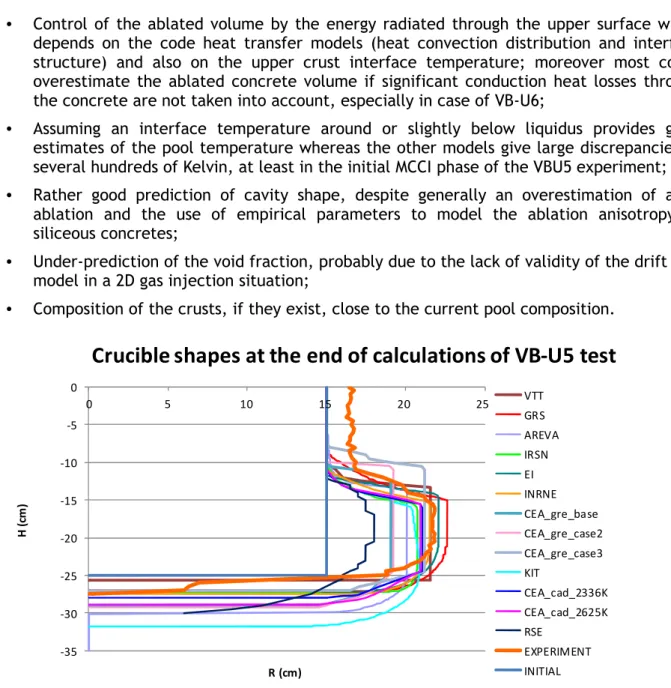
One of the unexpected results of the 2D MCCI experiments (e.g. at ANL [36] and CEA [37]) is the fact that, while limestone-rich concretes exhibit an isotropic ablation, silica-rich concretes are more ablated laterally than axially, which significantly affects the cavity melt-through kinetics. A series of separate-effect tests was performed in the VULCANO facility at CEA Cadarache with prototypic corium and specially-designed concretes in order to determine which of the differences between siliceous and calcareous concretes controls the ablation shape. Two of these tests were used for a benchmark on MCCI codes [38]: U5 (silica-rich concrete) and VB-U6 (limestone-rich concrete). Ten participants took part with different codes like TOLBIAC-ICB v3.2, ASTEC V2/MEDICIS, COSACO, CORQUENCH 3.03, WECHSL and CORIUM-2D (see e.g. Fig.3). The main conclusions of the benchmark were the following ones:
• Many similarities in the predicted trends but some major differences between modelling approaches;
• Control of the ablated volume by the energy radiated through the upper surface which depends on the code heat transfer models (heat convection distribution and interface structure) and also on the upper crust interface temperature; moreover most codes overestimate the ablated concrete volume if significant conduction heat losses through the concrete are not taken into account, especially in case of VB-U6;
• Assuming an interface temperature around or slightly below liquidus provides good estimates of the pool temperature whereas the other models give large discrepancies of several hundreds of Kelvin, at least in the initial MCCI phase of the VBU5 experiment; • Rather good prediction of cavity shape, despite generally an overestimation of axial
ablation and the use of empirical parameters to model the ablation anisotropy of siliceous concretes;
• Under-prediction of the void fraction, probably due to the lack of validity of the drift flux model in a 2D gas injection situation;
• Composition of the crusts, if they exist, close to the current pool composition.
-35 -30 -25 -20 -15 -10 -5 0 0 5 10 15 20 25 H (c m ) R (cm)
Crucible shapes at the end of calculations of VB-U5 test
VTT GRS AREVA IRSN EI INRNE CEA_gre_base CEA_gre_case2 CEA_gre_case3 KIT CEA_cad_2336K CEA_cad_2625K RSE EXPERIMENT INITIALFigure 3: Benchmark calculations of VULCANO VB-U5 cavity shape
Up to now, it is still not possible to propose a comprehensive modelling of MCCI that could predict the observed anisotropy and all the parameters of the experiments. But it must be reminded that multi-0D quasi-steady state modelling is used to model an intermittent ablation process with a complex geometry both at the interface and a complex convection pattern in the pool because of combined effects of gas bubbling and solutal convection. However, the interpretation of 2D MCCI experiments permitted to propose experimentally-validated sets of modelling parameters, although the models are still of parametric type.
To provide insights on the thermal-hydraulics of a MCCI pool, the CLARA experimental programme [39] with low temperature simulant fluids was performed at CEA Grenoble. The objective was to measure convective heat transfer coefficients on the lateral and bottom isothermal non-ablative walls of a pool percolated by air simulating the release of gas generated during MCCI. As for tests with gas injection both from bottom and lateral walls, the temperature in the pool was homogeneous; in case of a low fluid viscosity (below 0.025 Pa.s) the ratio of lateral convective heat coefficient to axial convective heat coefficient is higher than 1 whereas, in case of a higher fluid viscosity, this ratio becomes smaller than 1. For tests without gas
injection from the bottom, this ratio is much larger than 1, even for viscous fluids, and a significant temperature gradient appears in the pool. This demonstrated that the ablation anisotropy was neither caused by an effect of higher viscosity (associated to siliceous concretes) nor to gas moderate velocities (limestone concrete generating more gas than siliceous one). It is now considered that the cause of the observed anisotropy must lie at the melt pool interfaces. Smaller scale real material experiments have been conducted:
- SICOPS [40] by AREVA NP GmbH on interactions mixed oxide-metal/silicate concretes and
oxide/concrete. They showed that ablation/heat flux correlations were identical in 1D for classical siliceous concrete and for the EPR ferro-siliceous sacrificial concrete,
- COMETA [41] by UJV on thermochemistry of corium-concrete melts,
- Experimental work at JRC/ITU with laser heating to provide new data on corium phase
diagrams.
In support of the models coupling thermal-hydraulics and thermochemistry, the NUCLEA thermodynamic database [42] of the THERMODATA association has been improved through most above experimental activities, mainly the Ba-O-U, Mo-U, Mo-O-U, B-Fe-U and B-Ni systems.
3.2.2 Influence of metallic layer on MCCI
The previous sub-section was limited to single phase oxidic pools. Actually, corium is made of two phases (oxide, metal) with a miscibility gap. Two configurations are considered in the models: either the two phases form an emulsion that is assumed to behave as a homogenous equivalent fluid, or there is a gravitational stratification (the oxide becomes lighter than the metal due to the introduction of light concrete oxides). In this last case, heat transfer between the oxidic layer (where more than 90% of the decay heat is produced) and the lower metallic layer is larger than heat transfer at the oxidic layer sides. Reactor scale calculations indicate that the major uncertainty lies on the stratification thresholds: ASTEC calculations of a typical reactor sequence give a basemat melt-through between 2 and 6 days, depending only on the choice of threshold correlation.
Nowadays, two correlations exist for the heat transfer coefficient at a liquid/liquid horizontal interface. Two test series were performed in the ABI experimental program with simulants at CEA Grenoble: one with water or different oils over Wood's metal, and the other with gallium instead of Wood's metal. It indicated that heat transfer depends on properties of both liquids and of bubble sizes. A new correlation depending on bubble sizes has been fitted on the latest results as on earlier Werle and Greene data [43].
A series of large-scale MOCKA experiments have been performed at KIT [44] to study the interaction of a simulant oxide and metal melt in a stratified configuration. To allow for a long-term MCCI, additional enthalpy was supplied by means of alternating additions of thermite and Zr. Heat generated by the thermite reaction and exothermal oxidation of Zr was mainly deposited in the oxide phase. The experiments were performed in siliceous concrete crucibles with an inner diameter of 25 cm using initially 39 kg of Fe together with 3 or 4 kg Zr, overlaid by 70 kg oxide melt (Al2O3, CaO). The melt temperature at start of interaction was approximately
2173 K. The long-term axial erosion by the metallic phase became more pronounced and was a factor of 2-3 higher than the lateral ablation (Fig.4 left). This is in agreement with results obtained in the former BETA and COMET-L experiments at KIT. But, differently from these experiments, a significant lateral concrete erosion by the oxide melt was observed. One of the still unresolved issues is the long-term interaction of a melt with a reinforced concrete. New experiments were performed: two tests with iron rebars have shown an almost isotropic concrete ablation while tests (Fig.4 right) without rebars showed a preferential axial ablation.
Figure 4: MOCKA Experiments showing post-test cut views with initial cavity positions (left: test without rebars; right: test with rebars)
Post-test analyses of past VULCANO oxide-metal experiments [45] indicated that it is quite difficult to achieve a stable stratified configuration. A new VULCANO VBS-U4 test was performed by CEA with conditions favouring stratification. The test has been performed to verify whether the non-horizontal phase segregation between metal and oxide observed in the previous VBS-U2 and VBS-U3 experiments was due to the density ratio between phases in these tests. Therefore an initial oxide load composition with a significantly larger amount of light oxides has been chosen. The metallic phase has been formed not only as a bottom layer but also as vertical “tongues” on the vertical concrete walls (fortunately, it did not extend on the refractory inert wall, which would have prevented induction coupling). This phenomenon seems to be generic but is not understood yet.
3.2.3 Efficiency of corium cooling by water during MCCI
Water injection on top and/or bottom of a corium pool in the cavity is the main available mean to terminate the concrete ablation in Gen.II reactors. Recently, interest has been to pursue R&D on concepts that could be used to provide bottom-cooling in the cavity of current reactors. For new reactors (e.g. EPR), this has been realized by specific designs of the reactor cavity. Experiments have been performed to investigate the efficiency of water cooling of corium in the reactor cavity through top flooding, e.g. in the OECD MCCI project, and/or bottom injection. The activities aimed at research of potential back-fitting options for MCCI mitigation, with the ultimate goal to predict the efficiency of water cooling and to realize ex-vessel corium coolability. The joint interpretation of the water cooling tests performed in OECD-MCCI program (e.g. SSWICS1-13, CCI-6 [46]) and VULCANO VW-U1 COMET test [47] was carried out. These models can then be applied to reactor cases.
A broad literature review on bottom quenching, about the whole available set of experimental programs (COMET, DECOBI, VULCANO VW-U1, SSWICS12 & 13, and some separate-effect experiments), as well as modelling and simulations has also been carried out. Potentialities of WABE (USTUTT) and MC3D (IRSN) computer codes for bottom injection calculations have been assessed against the existing database, mainly the OECD MCCI experiments.
3.2.4 Bringing research results into reactor applications
Reactor applications are a necessary step to ensure that the R&D keeps linked to the industrial goals. A benchmark exercise was performed under the coordination of INRNE on a Station Black-Out scenario (with failure of secondary side BRU-A valve and pressurizer valve stuck open after reaching its set point) for a VVER-1000/V-320 reactor and a siliceous concrete in the cavity [48]. Seven partners joined the benchmark with 4 different codes. The comparison of the calculation results showed that there are no major differences between participant results, at least for the first 50 000 s. The remaining differences are linked to the hypotheses on stratification.
TRACTEBEL performed ASTEC MCCI calculations on a Belgian PWR on the influence of concrete water content on stratification [49]. It showed a drastic effect between 5.5 and 7.0 wt% of gas content in silica concrete through the impact on gas superficial velocity and on the metal inventory, leading to suppression of pool stratification and to delayed basemat melt-through for concrete high volatile (steam+ CO2) content.
3.2.5 Synthesis of outcomes on MCCI issues
An important activity was the writing of a SOAR on dry MCCI. Fruitful links have been established with the MCCI SOAR OECD/NEA project which has been decided later. Exchanges of draft sections have enabled a better homogeneity between the two documents which have different scopes since there is an important focus on coolability in the OECD/NEA SOAR. Some main lessons on MCCI in dry conditions were drawn:
- The discrepancy between the isotropic ablation of limestone-rich concretes and the larger
lateral ablation than vertical ablation of silica-rich concretes is mainly due to the structure of pool/concrete interfaces;
- For oxide/metal pools, phase repartitions are different from simple-layers assumptions
considered in MCCI codes and the stratification is stable but with a density contrast between phases typical only of the long term MCCI phase. There is also a strong effect of iron bars in concrete;
- Reactor applications in case of limestone-rich concrete did not show any pool stratification
with metal below and showed a late basemat melt-through after 8 days. In case of siliceous concrete, stratification seems possible and basemat melt-through occurs after only a few days (but many uncertainties remain in the latter case such as the assumption of prevailing lateral heat transfer as observed in experiments or increase of water content in concrete that might suppress pool stratification and delay the basemat melt-through very significantly).
The remaining uncertainties on MCCI in dry conditions were identified: 2D convection within the corium pool; prediction of the thermal resistance of the pool/concrete interfaces in the long term phase (in particular for a siliceous concrete); existence and stability of stratification of an oxide/metal pool; and, if any stratification, the induced 2D ablation in a situation involving a concrete with iron rebars. For wet conditions, the models for top and bottom flooding must be improved, in particular with respect to the role of gas sparging in competition with water cooling.
3.3 Containment issues
The progression of a severe accident may affect the atmosphere in the containment. Basically, the issue is the pressure increase, due to various phenomena, that may threaten the containment integrity. In the present section, major achievements on ex-vessel fuel-coolant interaction and hydrogen combustion are highlighted. A specific attention was paid to these phenomena since they may result in short term containment failure during a core melt accident. The use of Computational Fluid Dynamics (CFD) codes for detailed simulations of specific
phenomena and of lumped-parameter (LP) codes for safety analyses is also briefly discussed on the basis of computation exercises performed in SARNET.
3.3.1 Ex-vessel fuel-coolant interaction
Ex-vessel fuel-coolant interaction, i.e. interaction between the molten reactor core (spilled from the failed RPV) and the coolant, may lead to steam explosion, with possible damaging consequences on the containment [50]. Much research on that topic, especially experimental, has already been done within various projects, such as OECD SERENA. SARNET offered the opportunity for additional analytical work. The considered topics were fuel-coolant premixing, steam explosion triggering and explosion occurrence. On a lower length scale, the improvements of modelling focused on melt fragmentation and solidification, and void production and impact on steam explosion.
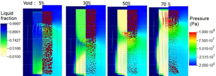
Regarding melt fragmentation, an outcome of the analytical work was that simple models, based on the Kelvin-Helmholtz instability, might be preferable to more complex models. Melt solidification is still considered as the major effect limiting (and possibly inhibiting) steam explosions. Research was directed to the development of models for predicting drop resistance to pressure perturbations, and to the development of multi-size group methods to describe the drops population. Void (i.e. gas phase) is suspected to have a strong influence in limiting explosion in some experiments. At reactor scale, most of the calculations tend to predict quite a large void around the melt jet. Two-dimensional simulations of phenomena at experiment scale (an example is shown in Fig.5) have shown that, despite high pressure, void never really collapses, except partly and locally at the passage of the shock front.
Figure 5: Visualization of flow in 2D calculations with MC3D code. Each picture represents a configuration at a given time for 4 initial void fractions (left part: liquid fraction and velocities
(arrows); right part: pressure and gas velocities (arrows); points represent melt fraction)
3.3.2 Hydrogen combustion and other phenomena
New experiments were performed on flame propagation in the ENACCEF facility, located at the ICARE institute of the CNRS (Centre National de la Recherche Scientifique) research centre in Orléans (France). In these experiments, a hydrogen-air mixture (with eventual additions of a gas mixture that has similar properties - heat capacity, thermal conductivity, diffusivity and diffusion coefficient of hydrogen in the gas mixture – as steam) in a 3.2 m long and 0.154 m i.d. vertical tube was ignited at the tube bottom, and the ensuing upward flame propagation was observed. Although the facility bears no resemblance to an actual NPP containment, experimental results are still useful for validation of combustion models.
Benchmark exercises were performed on such experiments on hydrogen combustion in a vertical tube [51]. Both CFD and LP codes were used, albeit results should be considered from different
perspectives: whereas CFD codes are supposed to be able to replicate accurately hydrogen combustion (i.e. the time-dependent pressure and temperature as well as the flame propagation), LP codes aim essentially at providing a realistic assessment of the maximum pressure and temperature. The CFD simulations (using codes ANSYS CFX and FLUENT, COM3D, FLACS, REACFLOW, TONUS-3D) have revealed that most of the used codes are able to predict pressure evolution satisfactorily. Nevertheless, the flame speed maximum value was generally overpredicted. This indicates that there are still limitations and weaknesses in the combustion models used in different codes. These limitations concern the chemistry part, the turbulent combustion model and the coupling between the two. On a different level (as explained above), simulations performed with LP codes (APROS, ASTEC, CONTAIN, TONUS) have confirmed their ability to simulate hydrogen combustion adequately.
Other benchmark exercises were organized on experiments on the following containment phenomena in order to identify the necessary model improvements:
- Atmosphere depressurization and mixing induced by containment sprays [52],
- Interaction between Passive Autocatalytic Recombiners (PAR) and containment
atmosphere,
- Steam condensation on the wall of a vertical channel [53].
CFD and LP codes were used in these benchmarks: CFD codes to study the basic phenomena (ANSYS CFX and FLUENT, CAST3M, GASFLOW, GOTHIC, NEPTUNE) and LP codes (ASTEC, COCOSYS, CONTAIN, ECART, FUMO, MELCOR, SPECTRA, TONUS) to validate the codes for use in safety analyses.
3.3.3 Generic containment benchmark
When modelling a containment of a real plant, simplifications are always necessary, as all the features can never be represented in a code input model. Nevertheless, when comparing results obtained by different users with different codes, it is customary to consider that differences due to subjective modelling choices are negligible in comparison to differences due to different physical models implemented in the codes.
The “generic containment benchmark” was organised in order to compare results of different LP codes without the influence of the simplifications done on a real containment [54]. A containment model was imagined, consisting of a limited number of usual PWR containment features (compartments, walls, flow conduits, etc…), with all the characteristics precisely and uniquely defined. All users were thus supposed to model the containment in the same way (without each one implementing own simplifications). Three different phases of the benchmark were organised, each time adding additional accident features to a basic scenario: firstly, thermal-hydraulics during the in-vessel phase; secondly, account for gas (H2, CO and CO2)
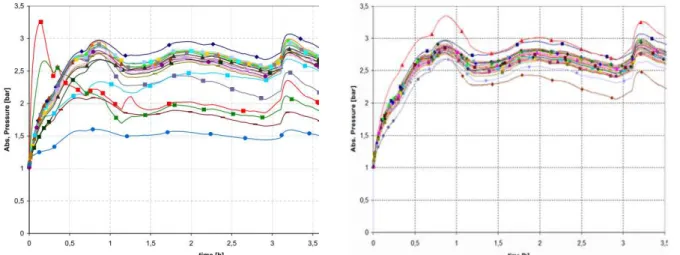
releases during the ex-vessel phase; and thirdly, PARs implementation. As expected, results obtained with different codes differed among themselves. However, results obtained with the same code differed as well, probably due to differences that could still be made when developing the input model. And differences between results of “blind” calculations (obtained by participants before seeing results from others) were much wider than between results of “open” calculations (obtained by participants after seeing results from others) (see Fig.6): clearly, many participants revised their initial input models in view of the results obtained by others, and identified features that should be modelled differently. However, had they not seen other results, they would never have become aware that their initial model was not adequate. This benchmark thus revealed the uncertainties of results of accident simulations performed with LP codes if there are no reference results. The main lesson learned is that, for results to be reliable, simulations should be performed at least with two different codes by independent analysis teams. The PWR containment model that was developed within this benchmark may also
be used in the future for the assessment of new versions of existing LP codes (or of novel LP codes).
Figure 6: Generic containment benchmark - Pressure in containment dome (the different curves show results obtained by different participants or different codes) - Left: “blind”
calculations - Right: “open” calculations
3.4 Source term
The effect of the oxidising environment on fission product release and transport has been addressed. Recent large scale experiments, like Phébus FP [6] and VERDON [54], have indicated that, once released, the ruthénium (Ru) amount eventually available for transport through the circuit is highly dependent on thermal-hydraulic core conditions. In Phébus FP, Ru release from the test bundle was low and occurred at the highest fuel temperatures (i.e. in the late oxidation phase). Nevertheless, the low Ru fraction entering the circuit from the core might be also related to Ru deposition on cooler surfaces downstream (i.e. upper bundle and bundle exit) in the form of RuO2particles, particularly in those tests with small gas flow rates through the core.
Separate-effect tests [55] highlighted that a fraction of Ru might reach the containment in the form of volatile RuO4, just because the prevailing thermal-hydraulics and fluid composition did
not allow reaching the decomposition equilibrium with RuO2. These experiments confirmed what
had been previous reported on the effects of air ingression in the reactor during core degradation [56]: the potential of a significant fraction of low-volatile elements, particularly Ru, to be released in a substantial amount in gaseous form as a consequence of their oxidation. Once in containment, a fraction of RuO4 would deposit on metallic and epoxy painted surfaces, but
revolatilization cannot be disregarded in humid atmospheres [57]. These observations suggest that an enhancement of the understanding of Ru release and chemistry in the RCS and the containment should be done, looking more deeply at possible re-volatilization.
Iodine chemistry and transport in the RCS has been experimentally tackled. Results from the Phébus FP experiments were compared to previous considerations: NUREG-1465 [58] stated that around 95% of iodine would enter containment in particulate form. This is consistent with the 1-2% iodine gas fractions measured in Phébus FPT1 and FPT2 tests, in the presence of Ag-In-Cd control rod in the fuel bundle [59]. However, the last FPT3 test, conducted in the presence of B4C control rod, led to iodine gas fractions as high as 97% [60]. Even though those results cannot
be straightforward extrapolated to BWR or PWR boron-controlled technologies because of lack of scaling in terms of amount and in-reactor material configuration, they were disturbing enough as to launch bench-scale tests that, although still ongoing, have already given some interesting insights into the iodine chemistry and transport through the RCS. The presence of molybdenum (Mo), which would be released in oxidising conditions during a core meltdown accident, enhances the gaseous iodine fraction reaching containment. Through interactions with caesium
(Cs) compounds, Mo would let less Cs available to form caesium iodide (CsI) and, as a consequence, gaseous iodine fraction would be higher (mostly as I2, although an HI fraction has
been also observed). Contrarily, under reducing conditions, the gaseous iodine fraction strongly decreases, the dominant iodine species being CsI. These findings come though from a limited number of analytical tests, and more experiments with other metals in the transported mixture (cadmium for instance) are planned to be carried out for a more thorough understanding of RCS iodine transport. However, such findings resulted in implementing preliminary versions of new kinetic models in ASTEC [61]. Additionally, some additional work is also ongoing to include boron, silver and cadmium effects.
A different in-containment iodine chemistry scenario has been set up. Recent research has questioned the traditional view that assumed aqueous iodine chemistry as the main source of gaseous iodine in containment and it has brought up other potential sources and sinks of gaseous iodine, like iodine interaction with paints and paint degradation products, reaction of iodine compounds with air radiolysis products and iodine oxides formation in the gas phase. Bench-scale studies [62] seem to confirm the potential formation of iodine oxides from iodine gaseous species, which is consistent with observations in larger scale experiments like Phébus FP and THAI [66]. These gas-to-particle conversion processes could contribute to maintain in the long run the airborne radionuclide contamination of the containment. A large number of small scale tests also addressed iodine-paint interactions under different frameworks [63]; the tests indicate iodine affinity for painted surfaces and, more importantly, the potential generation of volatile species coming out from those surfaces in the form of inorganic and organic iodides [64], notably in the gas phase. All these studies are instrumental to achieve a reasonable predictability of long-term airborne iodine activity levels. Figure 7 shows measurements from a bench-scale experiment in the EPICUR facility at IRSN where gaseous iodine comes out from an iodine-loaded painted coupon placed in the facility atmosphere It is worth to note that gas organic iodine release is faster than inorganic one and dominates the first hours of the test, although in the long run both species concentration got similar levels; besides, the amount of iodine released from the coupon in the form of particles is notably smaller than the gaseous one.
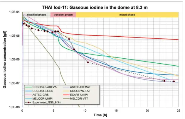
Figure 7: Gaseous iodine production from an iodine loaded painted coupon in EPICUR experiment Two code benchmark exercises have been performed on THAI Iod-11 and Iod-12 tests [66]. They showed that some thermal-hydraulics variables like gas temperature and pressure are well captured by codes, while a broad scatter was observed on relative humidity and condensation rates. Two major observations were made: the user effect was substantial and thermal-hydraulics largely affects iodine under the tested conditions. Additionally, a number of potential areas for improvement were identified, i.e. molecular iodine-steel interactions, iodine
wash-0 0,005 0,01 0,015 0,02 0,025 0,03 0,035 0,04 0,045 0 5 10 15 20 25 30 Time (hr) C u m u la ti v e re le a s e (a rb it ra ry u n it s ) Molecular iodine Organic iodide Aerosols
down modelling and nodalization effect. Figure 8 displays the code scattering when predicting gaseous iodine concentration during the mixed phase of THAI Iod-11.
Figure 8: Gaseous iodine evolution along time (data and estimates) – Test THAI Iod11 A benchmark exercise has also been completed on the Phébus FPT3 integral test that allowed to assess progress of simulation codes since ISP46 on FPT1 and to confirm the importance of the on-going research programs [67]. As for source term, the benchmark emphasized that presently estimates are overwhelmed by uncertainties in chemistry that, finally, resulted in major difficulties to predict gaseous iodine fraction in containment within an order of magnitude. Some of this drawback might be overcome by improving in-code models for some of the phenomena that are still uncertain, as discussed above.
4. ACTIVITIES ON THE ASTEC INTEGRAL CODE
IRSN and GRS jointly develop the ASTEC code (Fig.9) to describe the complete evolution of a severe accident in a nuclear water-cooled reactor [9]. The new series of versions V2 has been delivered to 30 SARNET partners since mid-2009. Among other improvements with respect to the former V1 series, it can simulate the EPRTM, especially its external core-catcher, and it includes
the core degradation models of the ICARE2 IRSN mechanistic code such as in-core 2D magma/debris relocation models. Three successive code revisions were delivered until mid-2013, accounting for the feedback of the maintenance efforts and including model improvements coming from the code assessment and from knowledge generated in the SARNET topical Work-Packages. For support to code users, IRSN organized two one-week training courses, and, with GRS, two Users Club meetings that gathered about 50 users.
Figure 9: Structure and modules of the ASTEC V2.0 integral code
The code was assessed by 30 partners (representing about 60 users), i.e. through validation vs. experiments [68] and benchmarks on plant applications [69]. The work on ASTEC improvements towards a better simulation of SAM in all main types of European NPPs is continuing from April 2013 in the CESAM FP7 new project, coordinated by GRS (see www.cesam-fp7.eu and [70]).
4.1. Validation versus experiments
Validation was done vs. more than 50 separate-effect or coupled-effect tests addressing most severe accident physical phenomena, as well as vs. a few integral experiments such as Phébus FP. The ASTEC V2 validation matrix was built-up in a way to provide a valuable extension of the former ASTEC V1 matrix [71], i.e. several new experiments have been simulated for the first time such as for example: RESCUE-2 on vessel external cooling, QUENCH-14 on bundle quenching with M5® cladding material, LIVE-L3 on corium behaviour in lower head, PACOS Px2.2 on spray
effect in German PWR containment, PPOOLEX Mix-04 on condensation in BWR containments. Good results (for more details, see [68]) were obtained on circuit two-phase thermal-hydraulics, core degradation (early phase, debris bed behaviour, corium behaviour in lower head, vessel mechanical failure) except in case of late quenching, release of fission products (except from molten corium pools), hydraulics of RPV external cooling, containment thermal-hydraulics, hydrogen combustion, aerosol behaviour and iodine behaviour in containment. The agreement was acceptable on MCCI where the models need further improvements of knowledge (as shown in Section 3.2 above), and on fission products transport and deposition where the crucial importance of gas phase chemistry has been underlined. This confirmed that most ASTEC models are today close to the state of the art. As an example in Fig.10, the comparison of ASTEC Phébus FPT3 calculations with the experimental data show that the evolution of bundle temperatures during the core degradation phase is well captured, as are that for the hydrogen
production (experimental uncertainty 5 % with one standard deviation), as demonstrated also in the FPT3 benchmark [67].
But the validation activities confirmed also the already known key-topics on which modelling efforts should focus in priority: reflooding of degraded cores (in particular for the corresponding hydrogen production where adequate models are missing at the moment in all integral codes worldwide), MCCI (in particular for the corium coolability aspects), RCS gas phase chemistry kinetics (pursuing the on-going IRSN development of a dedicated model), and, with a lower priority, pool-scrubbing phenomena in the containment and Direct Containment Heating.
Figure 10: Example of ASTEC V2 validation vs. Phébus FPT3 – Left: Bundle temperatures at 0.6 m elevation (ASTEC: curves 1 to 3 resp. for central control rod, fuel and clad of outer fuel rod, 5 and 8 resp. for inner and outer shroud surfaces; Experiment: curve 4 for outer fuel rod, 6 and 7
for inner shroud surface, 9 for outer shroud surface) - Right: Cumulated hydrogen production
4.2. Code-to-code benchmarks
Benchmarks with international reference codes showed the code applicability to most Gen.II-III NPPs, including EPR. More than 30 different Gen.II plant applications have been performed, covering several types of PWR (French 3-loop 900 MWe, Framatome 3-loop 1000 MWe, French 4-loop 1300 MWe, German Konvoi 4-4-loop 1300 MWe) and 2 types of VVER (6-4-loop VVER-440/V213 and 4-loop VVER-1000/V320), as well as to a lesser extent BWRs and PHWRs. These applications focused on the in-vessel phase but some were extended to ex-vessel phase, MCCI and/or source term evaluation: various kinds of initiating events (LOCA, SBO and LFW) and various break sizes and locations (VSBLOCA, SBLOCA, MBLOCA, LBLOCA and both cold leg and hot leg break location) were studied.
Most of these calculations have been compared with the equivalent ones performed using other codes such as RELAP5, CATHARE and ATHLET for the RCS thermal-hydraulics front-end phase, ATHLET-CD for the core degradation phase, COCOSYS for the containment behaviour, and of course MAAP and MELCOR integral codes for the whole severe accident sequence. These comparisons, in particular with MAAP and MELCOR results, concluded on a globally good agreement for in-vessel and ex-vessel severe accident progression, despite some differences in several of the studied scenarios such as on the RCS behaviour (on pressurizer modelling and hydro-accumulator discharge phase) and on core degradation (on timing of progression and on kinetics of hydrogen production). These discrepancies are mainly due to modelling differences in particular on the late-phase of in-vessel core degradation. Figure 11 illustrates a benchmark between ASTEC and MAAP codes, performed by AREVA NP SAS on a French PWR 900. The scenario
is a total loss of steam generator feed water (LFW), with loss of safety injection and opening of the Pressurizer Safety Relief Valves at core outlet temperature of 330°C and with unavailability of the emergency feed water and containment spray. As to core degradation, a majority of partners have finally adopted the advanced 2D magma model, thus following the IRSN recommendations for full-scale safety analyses.
Figure 11: ASTEC-MAAP benchmark on a PWR 900 LFW scenario - In-vessel hydrogen production (left), corium mass in vessel lower head (right)
Besides, as to the upgrade of VVER-440 reactors that are in operation in Central Europe, ASTEC V2 was used to demonstrate the efficiency of proposed plant modifications and adopted SAM strategies.
Nevertheless, several of these plant applications have also confirmed the difficulties to handle the violent thermal-hydraulics phenomena which are typical of the hydro-accumulators discharge phase. This limitation will be removed in the future ASTEC V2.1 major version (see the section below).
In order to underline the importance of uncertainty analysis, IRSN applied the ASTEC coupling with the SUNSET IRSN tool to evaluate the consequences of the identified lack of knowledge regarding iodine on final source term release to the environment[72].
4.3. Developments of the next major version
The assessment work done in SARNET has shown that ASTEC models were applicable to BWR and PHWR (or CANDU) reactors except for the core degradation phenomena, mainly due to the specific core geometry in these NPPs. IRSN has restructured in the last 2 years the ICARE module to account for new core components (square canisters in BWR and pressure tubes in PHWR) and for modelling of the associated multi-channels thermal-hydraulics with coolant flows inside these components and between them. BARC has implemented in the ASTEC development version new models of PHWR pressure tube thermal creep deformation and validated them vs. Indian experiments [73]. They performed also the first calculations of a Limited Core Damage Accident in a PHWR, as well as MCCI calculations in case of calandria failure.
In parallel, IRSN and GRS have continued working on the elaboration of the next ASTEC V2.1 major version for a planned delivery in early 2015. The CESAR/ICARE coupling technique has been strongly re-engineered, with ICARE module simulating now core heat-up and degradation from the beginning of the calculation and keeping CESAR active in the core all along the severe accident transient. The new version will include the abovementioned new core degradation models, as well as several other physical modelling improvements, notably on reflooding of severely damaged cores, MCCI coolability and source term, in accordance to the main outcomes from the extended ASTEC V2.0 assessment.
5. SPREADING OF EXCELLENCE AND KNOWLEDGE
Spreading of excellence activities [74] were mainly planned to disseminate the knowledge in the severe accident field to young researchers and students by an education and training programme and by mobility grants. The public web site (www.sar-net.eu) was continuously improved to provide more information on the severe accident researches to the general public.
Furthermore, periodic ERMSAR conferences (European Review Meeting on Severe Accident Research) were organized, becoming one of the major worldwide conferences on severe accident research. Dissemination of knowledge was also done through the publication of periodical newsletters and the participation to public events, with more than 120 papers released in scientific journals and more than 250 publications presented in national or international conferences since 2008. Six ERMSAR conferences have been organized as an exchange forum for the whole international severe accident community, three during the SARNET FP6 project (in France, Germany and Bulgaria) and three during the FP7 project: one hosted by ENEA at Bologna (I) in May 2010, one hosted by GRS at Cologne (D) in March 2012 and one hosted by IRSN at Avignon (F) in October 2013. The two latter were open to the international community and had a great success with around 150 participants from 25 countries and 60 organisations. The lectures at the Avignon conference [75], cornerstone between 8 years of FP6-7 SARNET projects and the future linked to the NUGENIA association (see Section FP6-7), addressed syntheses for the different topical issues and perspectives of R&D in the next years.
At the beginning of 2012, a textbook on severe accident phenomenology was published [76], covering the historical aspects of water-cooled reactor safety principles and the phenomena concerning in-vessel accident progression, early and late containment failure, fission product release and transport, including a description of reference analysis tools. This unique reference book emphasizes the prevention and management of a severe accident, in order to teach nuclear professionals how to mitigate potential risks to the public and the environment to the maximum possible extent.
Inside the education and training program, six courses have been organized since 2004, open to anybody even outside of SARNET partnership, three during the SARNET FP6 project and three during the FP7 project: one in Pisa (I) in January 2011 jointly organized by UNIPI and CEA, one in July 2012 in Karlsruhe (D) by KIT with a strong involvement of AREVA GmbH and CEA, and one in April 2013 at Imperial College London (UK), organized by ICL, CEA, IRSN and UNIPI. The courses covered severe accident phenomenology and progression in water-cooled Gen.II NPPs, but also the different design solutions in Gen.III ones addressing severe accident (i.e. the “in-vessel” melt retention or the “ex-vessel” core catcher). The participation reached between 60 to 100 Master or PhD students or young engineers and researchers from 20 countries worldwide. The Pisa and London 1-week courses had a strong link with the European Nuclear Education Network (ENEN) & the European Master of Science in Nuclear Engineering (EMSNE). The Karlsruhe 2-day shorter course aimed mainly at information for industry managers and senior scientists.
The Mobility Programme aimed at training researchers and students through a delegation towards SARNET research teams, in order to enhance the exchanges and the dissemination of knowledge in the severe accident area. Twenty-two mobility actions, with an average duration of about 4 months, were completed in the SARNET FP7 project, in addition to thirty-two ones in the FP6 project. The origin of delegates was quite diverse, with a balance of genders, without the predominance of Eastern Europe countries as in the FP6 project, and only 2 delegates on ASTEC training, which can be explained by the large progress of partners’ experience on ASTEC use and the large number of ASTEC courses and users clubs since 2004.
6. PERSPECTIVES FOR FURTHER R&D ON SEVERE ACCIDENTS
Knowledge on severe accident phenomena and modelling has considerably progressed in the recent decades and the efforts must now focus on improving SAM measures under extreme


![Figure 7: Gaseous iodine production from an iodine loaded painted coupon in EPICUR experiment Two code benchmark exercises have been performed on THAI Iod-11 and Iod-12 tests [66]](https://thumb-eu.123doks.com/thumbv2/123doknet/13178093.391041/18.892.218.624.689.971/figure-gaseous-production-painted-experiment-benchmark-exercises-performed.webp)