Design and Analysis of a Concrete Modular Housing System
Constructed With 3D Panels
by
Sam Rhea Sarcia
SUBMITTED TO THE DEPARTMENT OF MECHANICAL ENGINEERING IN PARTIAL FUFILLMENT OF THE REQUIRMENTS FOR THE DEGREE OF
BACHELOR OF SCIENCE IN MECHANICAL ENGINEERING AT THE
MASSACHUSETTS INSTITUTE OF TECHNOLOGY
JUNE 2004
© 2004 Sam Rhea Sarcia. All Rights Reserved
The author hereby grants MIT permission to reproduce and distribute publicly paper and electronic I copies of thesis document in whol"or in part.
f~~~~~
', ,:l ;.
.. I~~~/
Signature of Author:... . ... o ,x ,· .. o· . . .. .... ·... . .. o I, . -. ...o .... Department of Mechanical Engineering
/I _. May 7,2004
Certified by:... ... ... ... . . .
-.. . . / Jerome J. Connor
Professor of Civil Engineering Thesis Surervisor Accepted by:... .. ...-...
Ernest P. Cravalo Van Buren N. Hansford Faculty Fellow Professor of Mechanical Engineering
________ _____ ~ Chairman, Undergraduate Thesis Committee
MASSACHUSETTS INSI OF TECHNOLOGY
Design and Analysis of a Concrete Modular Housing System
Constructed With 3D Panels
by
Sam Rhea Sarcia
Submitted to the Department of Mechanical Engineering on May 7, 2004 in Partial Fulfillment of the Requirements for the Degree of Bachelor of Science in
Mechanical Engineering
ABSTRACT
An innovative modular house system design utilizing an alternative concrete residential building system called 3D panels is presented along with an overview of 3D panels as well as relevant methods and markets. The proposed design is an integrated approach to residential construction with unique provisions for structural elements and utilities. The design is hexagonally modular and may be scaled freely with a low number of unique components. An analysis of the house design in terms of labor requirements, construction
process, cost, and structural feasibility is also presented.
Thesis Supervisor: Jerome Connor Title: Professor of Civil Engineering
Table of Contents
Table of Figures
4
1.0 Introduction 5
2.0 Background
7
2.1 Concrete 7
2.2 Concrete Construction Methods 10
2.3 Construction Design Methodology 11
2.4 Residential Construction Methods 12
2.5 Concrete Homebuilding Systems 14
3.0 3D Panels
19
3.1 Introduction 19
3.2 Installation and Construction Methods 20
3.3 Shotcrete 25
3.4 Properties of 3D panels 33
3.5 Costs associated with 3D panel construction 35
3.6 Summary of benefits of 3D panel construction 36
3.7 Code Compliance and Verification 38
4.0 Proposed Modular House Design Using 3D panels
39
4.1 Form and Modularity 39
4.2 Joints and Assembly Methods 42
4.3 Construction Process 45 4.4 Utilities 47 4.5 Roof 51
5.0 Structural analysis
55
5.1 Panel Strength 55 5.2 Static Analysis 59 5.3 Design Feasibility 656.0 Conclusion
66
Works Consulted
_68
Appendices
70
Table of Figures
Figure 1: 3D panel cross section ... 19
Figure 2: Details for attaching 3D panels to foundations using steel reinforcement ... 21
Figure 3: Details of a splice and square joint for 3D panels using reinforcement mesh ... 21
Figure 4: Details of a hip or ridge joint for 3D panels using reinforcing steel ... 21
Figure 5: Details for terminating 3D panel edges for headers and jams ... 22
Figure 6: Details for attaching roofs to 3D panels ... 23
Figure 7: Assembly process for 3D panels ... I... 24
Figure 8: Continuous feed dry-mix shotcrete guns ... 27
Figure 9: Dry mix shotcrete equipment layout ... 28
Figure 10:Dry mix shotcrete nozzle ... 28
Figure 11: Shotcrete placement on a flat surface ... 29
Figure 12: Shotcrete placement in corners ... 30
Figure 13: Shotcrete being applied to 3D panels ... 31
Figure 14: 3D panels used across a roof span ... 32
Figure 15: Abbreviated simple span load tables for different 3D panel configurations ... 32
Figure 16: Observed thermodynamic performance of 3D panels ... 35
Figure 17:Basic structure and modularity of proposed house design ... 39
Figure 18:5 unit house layout ... 40
Figure 19:Different modular layouts for 3, 5, 7, 9, and 12 units ... 41
Figure 20: Joint proposed with continuous insulation ... 42
Figure 21:Interior wall joints in proposed design ... 44
Figure 22: Sub-assembled unique panels ... 45
Figure 23:Electrical conduits and face plate in corners ... 48
Figure 24:Electric distribution ... 49
Figure 25:Details for running a ventilation conduit through 3D panels ... 50
Figure 26:The 5 unit house indicating radiant heat flooring configuration ... 51
Figure 27: Assembled roof ... 52
Figure 28: Gutter and roof assembly ... 53
Figure 29:Dimensions used for structural analysis of 3D panels ... 55
Figure 30:Interaction curve for standard 3D panel per foot depth ... 57
Figure 31: Continuous gable cross section used for 2 dimensional static analysis ... 60
Figure 32: Force distribution per foot depth under gravity loading for 2 hinge gable frame of 3D panels in 8 inch thick configuration ... 61
Figure 33:Force distribution per foot depth under gravity loading for 3 hinge gable frame of 3D panels in 8 inch thick configuration ... 62
Figure 34: Force distribution per foot depth under gravity loading for 2 hinge gable frame of 3D panels in 8 inch thick configuration with a steel collar tie across the span... 62
Figure 35: Force distribution per foot depth under combined gravity and 40psf uneven snow loading for 2 hinge gable frame with collar tie ... 63
Figure 36: Force distribution per foot depth under combined gravity and 23psf wind loading for 2 hinge gable frame with collar tie ... 64
Figure 37: Force distribution per foot depth under combined gravity, uneven 40psf snow loading, and 23psf wind loading for 2 hinge gable frame with collar tie ... 64
1.0 Introduction
Concrete homebuilding systems are a fast growing segment of the ever-evolving residential construction industry. However, they are still underutilized in deference to traditional wood-light-frame methods which continue to dominate the industry as they have for centuries. While concrete is pervasively utilized in most construction fields because of its performance and cost qualities, its use in residential construction has generally been limited to foundation and other in-ground purposes. This fact is a result of both the context and structure of the residential construction market, as well as
manufacturing issues inherent to concrete building methods. However, such performance and cost advantages of concrete construction can, under the right circumstances, be
utilized in a residential environment as well. The emergence and development of various
successful residential-friendly concrete-based building systems over the past 25 years is a testament to this claim.
One such system is generically referred to as 3-D panels. In this system, a
structural sandwich panel is constructed by pneumatically or manually applying a layer of
concrete to each side of a reinforced polystyrene panel. The panel consists of two steel
wire mesh planes offset on either side of a polystyrene core and connected through the
core by steel truss wires that transverse the core periodically at alternating angles and are
welded to the mesh planes on either side. The resulting structural element provides
exceptional strength-to-weight and insulating properties as well as a good deal of design
flexibility. A major breakthrough in this system came when an Austrian company, EVG,
developed the machinery to manufacture such panels in the late 1980s. Since its
inception, the building system has been marketed internationally under various trade names and has been successfully used in both residential and commercial applications as
well as for landscaping purposes. However, to date the acceptance and utilization of these panels in the residential market has occurred at a relatively small scale as compared to
some other concrete homebuilding systems. Part of the reason for this underutilization is that traditional design and construction methods in-place must be altered significantly in order to achieve a sufficient level of economy.
Presented in this report is a design for a modular housing system constructed with 3D panels and respective analysis. The design of the system has been developed by the author and his father, Domenico Sarcia. The designers aimed to produce a unique commercially viable system and considered the associated construction process, form, and performance. More recently the author completed a further analysis of the resulting design regarding structural feasibility, energy efficiency, economic efficacy, as well as various matters pertaining to practicality. In conjunction with an overview of the proposed design and corresponding markets, materials and methods, these analyses and resultant conclusions are presented in this report.
2.0 Background
The following section introduces concrete as a building material and discusses its general use in construction industries. A brief overview of residential construction
industries is also given as well as an introduction to emerging concrete residential
construction methods.
2.1 Concrete1
Concrete is a unique material which has been developed and researched over the
thousands of years it has been in use. It is a composite of binding cement material and
small masonry aggregates that behaves in an effectively homogenous fashion. The hydraulic cements used in concrete are initially fine powders that, when combined with water, undergo an irreversible exothermic reaction at the molecular level called
hydration. The result is a material with adhesive and cohesive properties. Portland cement was first patented in England in 1824 and is the cement most widely used today. The functional ingredients are calcium and aluminum silicates naturally occurring in limestone, shale, and clays. Such naturally existing materials are mixed and processed along with other materials to produce portland cement in its useable fine gray powder form. Complete hydration of portland cement generally occurs at a 4:1 ratio, by weight, of cement and water. However, adding water in excess of the amount needed to hydrate the cement is necessary to facilitate the interaction and helps make the mixture more fluid and workable. In concrete, stone aggregates of various sizes are mixed with the cement before or at the same time as adding water and generally attribute 75 percent of the final concrete volume. Aggregates are mixed proportionally to reduce the interstitial volume
that the cement must fill. After being set, the concrete is cured as full hydration takes place. The cement binds the aggregate particles in place and creates a structural matrix that is effectively homogeneous at practical scales.
Any water in addition to that used by hydration will exist in the concrete as voids as it sets which affects the concrete's structural properties. Water to cement ratios
between .4 and .7 are usually used, over which range the compressive strength decreases by half. While generally, the cement gains its structural properties at varying rates over a
28 day curing period at which point it reaches final strength, some portland cements can achieve full strength in 14 days. Initial set of the concrete occurs early on after being
placed and up to 70 percent of the strength exists after the first week. Reaching maximum strength requires maintaining favorable environmental conditions while the concrete cures such as avoiding low temperatures and preventing premature drying out of the
surface.
As a structural material, concrete deviates significantly from the linear elastic model that successfully predicts the behavior of most materials. The most fundamental difference is that concrete's compressive strength overwhelmingly exceeds its tensile
strength. The relationship between stress and deformation as well as the impact of stress
state on strength also vary significantly between concrete and linear elastic materials. In order to reconcile such deviations, research over time has developed models exclusively for concrete behavior based largely on experiential data
The relationship between composition and concrete behavior has also been investigated and manipulated extensively. Components are proportioned to achieve a required balance between mixture economy, final strength, early strength, curing time, and mixture workability while being placed (characterized by a field test and known as slump). In addition to variations based on aggregate sizing, water-cement ratio, and cement proportioning, concrete behavior is affected through use of materials known as admixtures which are mixed in with portland cement in either liquid or powder form. These admixtures are a variety of materials and are used for several different purposes. Air entraining admixtures create small air bubble voids in the cement which decrease strength in the same manner as extra water but also increase the fluidity of a mixture for a given water-to-cement ratio and increase the concrete's durability. Set-retarding
admixtures slow the setting process such that concrete may be kept in workable form longer while being placed if need-be. Conversely, accelerating admixtures speeds up the set process such that strength develops faster. Water-reducing admixtures are also known as plasticizers and decrease the amount of water needed for a mixture to achieve certain
level of workability or slump. Additionally, short fibers are sometimes mixed in with the concrete mix to carry loads within the concrete when in tension, thereby increasing
Many different materials and sizes of aggregates can used in concrete but in structural concrete lightweight processed aggregates are primarily used. These aggregates are similar materials to those used in manufacturing cement and the resulting concrete
generally has a density between 60 and 150 pounds per cubic foot.
Characterizing the performance of concrete starts with the final compressive strength, f' , from which other properties may be determined based upon empirical relationships. When short-term loading occurs, stress increases linearly with strain much like the linear-elastic model. Depending on the density and strength of the concrete, the modulus of elasticity is estimated using one of several equations, the most simple of
which is for normal sand and stone concrete as presented in Equation 1:
Ec = 57,000/f' (Equation 1)
where the density of the concrete is assumed to be 145 pounds per cubic foot. Equation 1 is suitable for the analyses of the present research but other equations further consider the density and ultimate strength of the concrete. Atf', strain is usually between 0.002 and 0.004. The Poisson's ratio characterizing the orthogonal strain is valid up to around 0.7f'c and is between 0.15 and 0.20. When concrete is loaded for periods of time on the order of
100 days, creep increases the strain for a given load by up to 3 times. Also, fatigue is a
consideration in concrete and the fatigue limit of concrete is about half that off'c for on the order of 2 million loading cycles. These are phenomena that must be accounted for in structural use of concrete. In tension, the strength of concrete is on the order of the square root of f'c but the exact relationship varies between different concretes. When overloaded
in tension, concrete separates and cracks. Additionally, in biaxial stress states, the
strength in one direction is alerted by up to 20 percent depending on the stress state of the
orthogonal direction. Orthogonal compression increases the effective strength while tension decreases it. Shrinkage and temperature effects are also considered for concrete. Information on concrete behavior is plentiful and the previous summary is very cursory but gives an introduction none-the-less.
There are many parameters involved in designing and creating a concrete mixture (known as batching), and the results are ultimately a balance of the properties required of
the concrete as well as the availability and economy of resources. Detailed standards and
protocols are in place for batching and placing concrete, which are based both on theory
and statistical analysis of experimental data. After being mixed, performance of a batch
may be verified with tests in the field and lab to ensure slump and strength.
2.2 Concrete Construction Methods
Early structures built with concrete and similar materials utilized its mechanical
properties by designing structural members in compression. Such structures employ
members like arches to avoid tensile stresses for which concrete has very little resistance. However, these design constraints are quite limiting and as a result, the practice of
reinforced concrete construction came about in the mid 1900s. The concept involves combining lengths of steel with concrete beams to withstand the tensile forces as the
yield strength of steel in tension and compression is generally ten times that of concrete
such that members of much smaller cross sectional carry equivalent loads. However, steel is much more expensive than concrete and members that are of significant length will fail by buckling in compression long before yield loads are reached. Accordingly, reinforced
concrete construction utilizes the best qualities of both materials; the concrete resists compression and prevents buckling of the steel rods known as re-bar in construction
while the steel reinforcement resists tensile loads. The rebar surface is textured in order for the concrete to bind to and around it and the two materials have similar thermal
expansion coefficients which enable such construction to work. In buildings, tensile forces usually result from bending moments in a beam rather than uniform tension of a
cross section, so the reinforcing steel is placed near the tension surface away from the bending axis in order to provide the greatest moment resistance.
Utilizing concrete in construction requires batching it, transporting it to and around the construction site, and supporting it while it cures. Usually batching is done in a dedicated plant where conditions can be easily manipulated but is sometimes done on site for smaller scale uses. It is transported to a work site with dedicated trucks which constantly keep the concrete in motion to prevent setting. Onsite, it is either poured directly in place from the truck or pumped through a hose to the final destination.
Because it is fluid when being placed, the concrete must be constrained and supported by
other and relative to time in order to succeed. Alternatively, concrete may be sprayed in place pneumatically by a process known as shotcrete which will be discussed in further
detail later in this report.
The availability and low cost of concrete combined with its flexibility in construction drives the pervasive use of it in practice. Conversely, the need to properly contain and cure concrete in the construction process requires consideration of
environmental conditions, time-schedule, quality control, and special equipment in addition to the planning needed for construction with materials that arrive on site in full structural form. Also, structural analysis and design of concrete requires in depth
knowledge of concrete behavior and construction methods. These special considerations mean that concrete construction is most effectively done on a large scale by designers, engineers, and construction crews specializing in such construction.
2.3 Construction Design Methodology
Deciding how durable a building structure must be is a pretty complex process.
On a most basic level a building needs to serve its designated purpose and maintain its
function over a period of time. Usually, this requirement means that a building needs to be strong and stiff enough to resist loading that it may encounter during service and still
maintain its form and function. A building must also be able to withstand deterioration from elements such as water and fire. In construction, there are guidelines to determine
the service loading that a structure could expect and associate frameworks to construct a building capable of withstanding such loads. The process centers around traditional mechanical structural analysis methods and these guidelines seek to organize similar structures and characterize their performance based on parameters determined from both
structural analysis and real world experience. Codes exist related to design analysis as
well as construction methods. Design codes consider the environmental conditions a building can expect based on its location related to wind loading, seismic loading, as well
as water and snow loading. Methods are also in place to predict the strength of a structure such that a design may be matched to its location. Generally, these codes are regulated and enforced by the local government but standards are often also developed by industry
Many different codes exist across the numerous industries involved in
construction. Some notable standards are those developed by the American Concrete
Institute (ACI) that govern strength analysis and construction processes related to
concrete construction. Other groups such as the American Society of Civil Engineers (ASCE), American National Standards Institute (ANSI), and the American Society for Testing and Materials (ASTM) also have developed standards. For residential
construction, the exact standards are designated by the local building inspector but most
guidelines reflect those set forth in the International Residential Code which is endorsed
by a variety of relevant associations.
Historically two different design methods have been used to develop codes. The older method essentially predicted the loads a building would see from a day to day basis
and designed the structural strength such that those loading conditions would be
somewhere in the middle of the strength curve. This method is similar to the use of safety factors, assuming that the building materials will always remain within the linear elastic
regions of their stress-strain curves. However, the problems that resulted from such methods were that when a rare loading case occurred such as an earthquake or extremely
high winds not expected by the design analysis, the buildings would often fail. The newer method often call ultimate strength design (USD) seeks to consider the highest loading a building would ever see even if it be very rare and requires the building not to fail under
such a case. However, because ultimate strength is considered, the materials must be modeled beyond their elastic regions complicating analyses. Such a method matches
concrete construction well because inelastic analysis methods already must be used as noted previously. Generally, all codes and standards are now based on USD methods.
2.4 Residential Construction Methods
On the other extreme of the spectrum from large scale reinforced concrete
construction is residential construction. While each building constructed with reinforced concrete involves extensive planning and analysis, residential structures require fast high-volume construction methods that may be carried out by available labor and analysis
methods that may be applied universally. Accordingly, the two industries are extremely different and largely independent.
The overwhelmingly dominant method of residential construction is known as wood-light-frame construction. Houses built with this method are built upon of frames made from standard, widely available wood lumber. All the pieces of lumber are
assembled one by one onsite and each piece can usually be manipulated by one person.
Outside and inside sheeting materials complete the structure and service equipment is also built into the building. This equipment is generally, doors and windows, electrical wiring and related hardware, plumbing and related hardware, and ventilation provisions.
The methods for residential building are complicated and the exact details are not
as important as the general structure of the process. While houses may be built in many
different shapes and orientations, the design is constructed using standardized materials and construction methods. Because of this standardization, the sub-components of each house may be completed by different constructions crews specializing in each component without requiring extensive communication between the crews or architect in addition to blueprints. This frame-work also allows materials to be processed for use onsite with little to no modification from the form they are marketed in. The following is a brief
overview of the process.
The land to be built on is first cleared and a foundation is excavated. Once a foundation is poured the frame is erected. Walls are generally framed with 2 x lumbers
while floor joists and roof frames or trusses often use pre-manufactured wood beams.
Additionally, elements such as stairs are also framed with wood. Once the framing is completed, the exterior surface is covered and the walls are completed with insulation,
windows and doors, and appropriate water barriers. Crews also work on installing the mechanical. electrical and plumbing infrastructures. Usually one crew is responsible for
each system and it is the responsibility of each crew to work out the exact details of the system to be installed. Another crew also installs the roofing and one installs the interior drywall surface.
A contractor works with the owner and architect to develop plans for the house and then manages all the different sub-contractor teams. While different materials and proprietary systems to be used during construction have been developed, the houses built
labor market is not unionized. Generally, such methods are considered inefficient and various efforts such as pre-manufactured housing have been used to improve on the
associated economy. Many initiatives for better building methods have emerged over the
past years and people want to make houses more energy efficient and less expensive to
build. However, any of these improvements have to battle a huge in-place industry that
they seek to displace in large part. Such resistance from the market combined with material and labor resource issues have prevented maximum utilization of such
innovations in large part. The successful innovations are those that can be integrated into
the existing system without much reorganization of the construction process or labor
break down. Manufactured components that are improvements on but still adhere to the
independent subcomponent system have seen reasonable success.
Another aspect of the residential market is developing and approving designs. Just
as standards components and methods are used to achieve economy, standardized
analysis methods are in place for designing residential structures. It is not cost effective
to undertake a full analysis of each home built so the design codes and methods are such
that a building design may be characterized and judged without a complete analysis. The
use of standardized components and methods makes this type of structural verification
possible.
2.5 Concrete Homebuilding Systems2
Concrete has historically found limited use in residential systems despite the
benefits associated with it. The heavily involved timing of separate crews and need for flexibility in schedule often prevent the use of concrete which much be managed relative to time. Also, the need for unique construction methods for proper installation leads residential builders to pass over it in preference to using components which are more
forgiving. However, systems that utilize concrete in a residential friendly manner have
emerged over the past quarter century and are gradually gaining acceptance. A variety of
different products are being developed and used and offer the traditional benefits of concrete as well as emerging ones as listed in table 1.
2Primary source: Vanderwerf P., Munsell, W.K. (1994). The Portland Cement Association's Guide to
Table 1. Benefits of Concrete Structures
From Concrete Homebuilding Systems, VanderWerf and Munsell
Traditional Emerging
Price stability Low cost
Supply stability Attractive finishes
Durability High R-value
Low maintenance Design flexibility
Fire resistance Water resistance
Wind resistance Earthquake resistance
Reduced insurance premiums Speed of construction Thermal mass and energy efficiency Ease of construction Termite and insect resistance All-weather construction
Rodent resistance Low skill requirements
Rot resistance Local Supply
Sound resistance Nontoxicity
Before recently, concrete in residential settings was poured or used as pre-cast block systems that had to be mortared together. The old block and mortar systems had many problems with moisture resistance and they also didn't provide the full versatility of cast on site concrete methods. Buildings that were built with the block and mortar system often utilized two building envelopes separated by insulation and drainage provisions. The interior envelop was either a traditional wood frame or a masonry one like the exterior.
However, modem residential concrete products are a far cry from traditional block and mortar methods. Aside from the durability and other benefits associated with these products, the growth of the concrete residential market has been mostly market
driven. Builders generally only use the systems if the owner puts a higher value on
concrete or if they may be used to produce the same building for a lower cost. Spikes in lumber prices drove a lot of the early use of concrete systems.
When builders began using concrete because of economy, the system to be used was evaluated in context of the existing labor and time framework. Accordingly, systems that didn't require much extra labor or higher learning costs were the most appealing.
More recently such economy aspects still drive the use of concrete but the desire for more durable structures has become more of a concern. As homeowners become more
educated and technology develops, traditional wood-light-frame methods are seen as more and more antiquated as compared to the residential buildings possible today with concrete. While this trend is nowhere near as wide spread as possible, it is gaining
ground.
In 1995, Pieter A. VanderWerf and W. Keith Munsell of the Portland Cement
Association published a book Concrete Homebuilding Systems describing and evaluating the various concrete systems on the market. Their research included talking with the manufacturers of each product as well as surveying builders who had experience with each system. Because their research was completed at a time when these systems were relatively new, the builders they surveyed were mostly traditional builders trying out the new systems. Accordingly, they present each system in terms of its potential benefits as well as in terms of being integrated into the traditional building process. The research also surveyed owners of homes built with concrete in order to examine the market factors driving the utilization of each system. Their conclusions were that the residential concrete
market may be broken up into 5 segments: value, quality, cost, safety, and energy. While
these segments are inevitably interrelated, they are identified independently as the primary motivation for choosing to use a concrete system. Also, the research primarily concerned the use of concrete systems for exterior walls.
Before comparing different construction systems, characteristics must be selected
upon which to judge, the most obvious of which is cost. As a bench mark the cost break
down of traditional wooden wall frame construction per square foot of exterior wall is
Table 2. Approximate Costs of 2-x-4 Wood Frame Exterior Walls
From Concrete Homebuilding Systems, VanderWerf and Munsell
Component Cost per square foot wall area
Structure and Insulation
Materials 1.40
Labor 1.05
Subtotal $2.45
Finishes (material and labor)
Exterior siding 0.80-9.50
Interior sheetrock 0.80
Interior paint 0.70
Subtotal $2.30-11.00
Total $4.75-13.45
The thermodynamic performance of a structure is also very important to cost as it affects the amount of energy needed to maintain comfortable living conditions while the
environmental conditions vary. The propensity of a cross section to transfer heat across it is considered in terms of thermal resistance; the higher the thermal resistance, the less heat will flow across the cross section for a given temperature differential. In
construction, thermal resistance is characterized as an "R value". For a traditional wood frame wall, the R value is determined by the geometry and composition of the different
materials from which it is constructed. While different forms of the R-value are used for
different types of analyses, the most basic is the insulation R value which is R- 11 for a
standard stud wall. Another consideration regarding thermodynamic performance of a cross section is called "thermal mass" which is the heat holding capacity as determined from the specific heats of the materials. For example, a building with high thermal mass
walls will absorbed heat during the day and slowly release it as the temperature drops at
night. Depending on the environmental fluctuations, thermal mass will provided passive heating and cooling in order to achieve the same energy requirements with a lower
insulating value. Thermal mass on the interior surface as well as on the external surface of the building may be beneficial.
When evaluating the insulating capacity of a whole building envelope, any break of the insulating cross section will lower the value. Aside from openings such as
windows and doors, structural elements with a low thermal resistance that cross the
insulation barrier lower the value. These conductive pathways are referred to as thermal
shorts.
Other factors that come into play when evaluating wall systems are the
maintenance required, resistance to elements, product availability, building department approval, disaster resistance, required calendar time, and installation simplicity.
Mortar and block systems like those that used to be available are still in use and
manufacturing improvements have led to much better connections and lower cost. Also now in use is mortar-less block systems which are stacked together without mortar between them but rather applied to the surface of the seam. This improvement increased the dimensional precision of such a method and eliminated a lot of the labor involved in
assembly. Panel systems are also presently available where large hybrid wall panels are
manufactured with pre-cast concrete and brought to the work site for assembly. The
systems just described arrive on site in final structural form and are quite different from methods where concrete is cast on site. One such cast on site method is that of insulating
concrete forms (ICFs). ICFs are presently the most widely used residential concrete
system. Insulating forms are assembled to create a free standing wall with an outside and
inside insulation layer and internal cavity. Concrete is pumped into the cavity from the
top to make a final wall that has a monolithic concrete core with insulation on either side.
Interior and exterior finishes are applied to the insulation and utility management is
integrated into the system as well. While such a system is simple and easy to build with,
the resulting wall is not efficient from a structural or thermodynamic standpoint because the load bearing, conductive component is closest to the wall's neutral axis requiring
relatively thick cross sections. An alternative method is that of 3D panels which is
3.0 3D Panels
3.1 Introduction
3D wall panels emerged as a form of concrete wall construction in the late 80s.
Concrete is applied once the panels are in place by pneumatically spraying it onto the
surface (known as shotcrete). The cross section of the panel is shown in Figure 1.
Ordnal 'k.e"' wlroa
Figure 1: 3D panel cross section
From NER-454
The welded wire fabric is galvanized or untreated steel wire spot-welded together
into a 2 inch by 2 inch square grid. The "truss" wires are also spot welded to the wire
grids at alternating angles and pierce through a block of insulating foam (either expanded polystyrene of molded EPS). The panels come in a variety of configurations based on
materials and dimensions. In a standard panel wires are 11 gauge, the two wire grids are 4 inches apart with a 2.5 inch insulating core. The shotcrete may be applied to a variety of thicknesses but in standard panels a 1.5 inch layer is applied to each side to give a final wall thickness of 5.5 inches. Panels are connected with ring clips where the welded wire grids meet and additional mesh is placed over the seam and ring clipped to each wire grid. The resulting structural panel cross section is very strong and provides great
hurricane Andrew swept through Florida in 1992; most all residential buildings hit by the hurricane were destroyed except for 14 houses built with 3D panels by Habitat for
Humanity whose roofs were destroyed but walls remained unharmed3. Such disaster resistance primarily drives the market for 3D panel construction which is mostly concentrated in the southeast and southwest.
An Austrian company, EVG, who makes machinery to manufacture wire mesh,
developed the machine to make the panels. The high speed machine takes the raw material and makes the panels with high precision. Panels are manufactured in 4 foot
widths and weigh little more than 1 pound per square foot before shotcrete is applied. The panels are usually sold under the broad trade name Insteel 3D Panels and distributed internationally under different brands. Each distributor generally owns one of the
machines and makes the panels on site. The panels may be used for a variety of purposes
including residential construction. Many tests and analyses have been performed on the
panels and the distributors provide documentation on test performance, code compliance, and panel strength.
3.2 Installation and Construction Methods
In residential construction, the panels are usually used for walls but sometimes used for foundations and more rarely for roofs. For walls, the panels are assembled
vertically and tied to rebar sticking out of the foundation. Typical details for a foundation
joint are shown in figure 2. Reinforcing mesh is placed over the seams and around
corners to create a continuous joint. Typical details for a splice and corner joint are shown in figure 3. Additionally, ridge joints may be designed to transfer significant
moments with reinforcing steel as described in the typical details shown in figure 4.
"II
i
t}~~~~
Figure 2: Details for attaching 3D panels to foundations using steel reinforcement
From ICS 3-D Panel Works Complete Typical Details
_ ' 1 -'
I ' '
I ' ' is ' l ' I ': It ' ' I: ' i
Figure 3: Details of a splice and square joint for 3D
From ICS 3-D Panel Works Complete
panels using reinforcement mesh
Typical Details
Figure 4: Details of a hip or ridge joint for 3D panels using reinforcing steel
From ICS 3-D Panel Works Complete Typical Details
...
Cutouts for windows and doors are removed usually once the panels are erected. The steel grid facilitates easily locating and cutting square holes in the panels but
most any shape may be cut out and shotcreted around. A handheld reciprocating metal cutting saw easily makes the cuts. Rebar is tied into the grid above the openings to resist the resulting tensile loads there and wire mesh overlay is attached at 45 degrees to the
grid at the corners to resist the stresses that develop there. Wooden bucks are usually used to frame the inside of the window or door inside of which a conventional frame may be mounted. Typical details for a header and jamb of an opening are shown in figure 5. In the case where a panel end is terminated but a wooden jamb isn't used, overlay mesh bent
in a U pattern terminates the panel as described by the typical details also shown in figure
5.
...
Figure 5: Details for terminating 3D panel edges for headers and jams
From ICS 3-D Panel Works Complete Typical Details
Presently, utilities are installed by removing some of the wire and insulation
core and running conduits inside of the wire mesh before shotcreting. For the most part, 3D panels are only used for vertical walls but are sometimes used across a span.
Additional rebar must be run along the tension side of such a panel in bending but the
manufacturer suggests that the panels may be used to support significant loads for simply
supported spans of up to 20 feet. Regardless, when used with a manufactured truss or frame roof, truss anchors are inserted into the top edge of the panels as shown in figure 6.
Figure 6: Details for attaching roofs to 3D panels
From ICS 3-D Panel Works Complete Typical Details
Before shotcreting the panels are also braced temporarily to resist the impulse against the
wall caused by the shotcrete being sprayed. The panel assembly process is very quick,
Panels arrive on site; a
4'x8' standard panel
weighs only 38 pounds.
Windows and doors are cut out with a
reciprocating saw and wooden frames are usually inserted.
Walls are braced for shotcreting.
Some of the wire and
insulation is removed to run utilities inside the wall
Figure 7: Assembly process for 3D panels
s are assembled and connected to ation rebar. Mesh strips overlay
and wires are clipped together
a special tool I
Panel,,
found joints
3.3 Shotcrete4
After the panels are assembled and readied, the shotcreting process begins. Shotcrete came about as a method of placing concrete in the early 1900s. Shotcrete is good for its versatility and because it does not require any constraining of the concrete while it cures. It is used extensively to repair buildings, bridges, marine structures, and spillway surfaces, for underground excavation and tunnel reinforcement, for slope and surface protection and for new construction of pools, tanks, domes, and floors. There are
two types of shotcrete: wet mix, and dry mix. In wet mix shotcrete, the concrete mix is
combined with water before it is pumped to the applying nozzle with high pressure air.
Alternately, in dry mix shotcrete, also known as gunite, the cement and aggregate is
mixed before being pumped to the nozzle where a separate water feed is added. Both methods are used and each has its benefits and disadvantages. Gunite is better for intermediate use and small scale projects because the hydration of the concrete mix isn't
initiated until the nozzle and the water may be adjusted as needed, while wet mix
methods are better suited for high volume continuous use situations where the water-cement ratio must be consistent. Additionally, gunite precludes the use of any admixtures
aside from accelerators which means that the freeze-thaw durability of the concrete can not be improved with air entraining admixtures. Neither method can make use of air entraining cements either. However, gunite provides higher final and bond strengths and, if done correctly, will not produce cold joints from intermediate application. Accordingly, gunite is the method of choice for 3D panels; managing the concrete becomes much more suited to residential organization and the geometry of the concrete and reinforcement does not require exceptional strength or freeze-thaw resistance that could only be achieved using admixtures.
The materials used in gunite are the same as those used in regular concrete
though aggregate sizing is limited by the passages and hoses the mix must travel through so smaller sizes only are used. Cement and aggregates are mixed offsite and delivered or mixed onsite with prepackaged bags of cement. When it is delivered from offsite the mixture is already at the 3 to 6 percent moisture content necessary for proper equipment use but mixtures made from bagged cement must be pre-moistened onsite as well.
Accelerating admixtures may also be added to the mix in powder form giving an initial
set in as little as 1 minute and a final set in as little as 4 minutes. Silica fume is also
sometimes mixed with the concrete to improve performance. A waste product of silicon alloy production in submerged electric furnaces, it reduces permeability, increases density, strength, and durability but is relatively costly compared to the other materials. Generally no special additives are used in the concrete for residential 3D panels and
aggregates are coarse sand with no gravel. Also, a 2 inch slump is usually used and 3000 psi concrete is suggested by the manufacturer.
When being sprayed onto a surface at high pressure, a portion of the mixture bounces off and is called rebound. Shotcrete may be applied to both vertical and horizontal surfaces but the rebound varies accordingly. Table 3 shows the rebound expected for these different situations. When proportioning a mix it must be considered that because of the differences in density, the aggregate bounces off more readily leading to higher cement content in the remaining concrete. Test panels may be used to check the
12 hour, 7 day, and 28 day strengths of the concrete but usually is only necessary if
strength above 5000 psi is specified. Table 3 relates the final 28 day compressive strength
of dry-mix applied concrete with cement content. Strength develops early in gunite even
without accelerators, developing up to 1000 psi in the first 5 hours of curing and up to 3000 psi in the first 24 hours. Because of the impulse force involved in spraying concrete onto the work surface, the resulting bind strength to reinforcing steel is higher than with
poured concrete. However, the reinforcement must be spaced widely enough that the shotcrete can fully encapsulate it.
Table 3. Rebound for shotcrete on various surfaces
From ASCE Standard Practice for Shotcrete
Work surface Percent rebound by mass for dry mix
Floors and slabs 5-15
Sloping and vertical walls 5-25
Table 4. Shotcrete strengthf' for different cement contents
From ASCE Standard Practice for Shotcrete
28 day comp. strength Cement content
(psi) (lbs/cubic yard)
3000 500-650
4000 550-700
_5000 650-850
In small scale residential construction, shotcreting in performed by a dedicated crew using relatively little specialized equipment. If mixed onsite, portable batching equipment and a pre-moisturizer are used but mixtures delivered from offsite are directly
fed into what is called a gun. The more common type is a continuous feed gun that
consists of a hopper that receives the pre-moistened mixture and meters it into a hose to
which a portable air compressor supply is attached. The air drives the mixture through the
hose to a nozzle in which a perforated water ring supplies the water. The pneumatic
spraying action is enough to thoroughly mix the water and mixture. It is also notable that
this method of mixing and placement lowers the need for extra water to improve
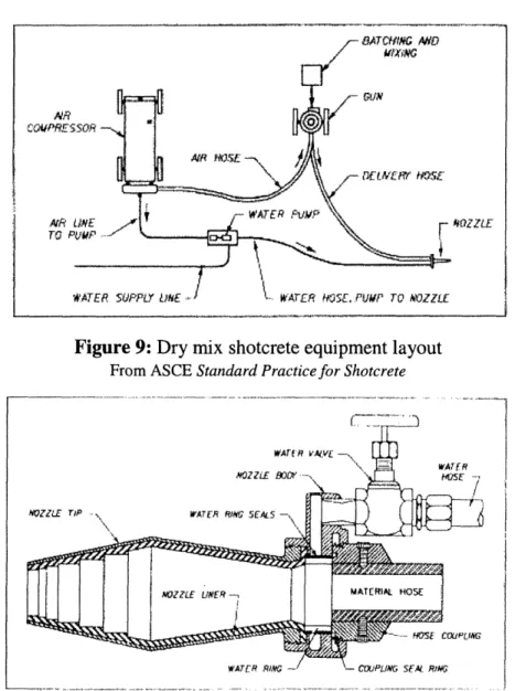
workability and uses a relatively low water-cement ratio. Figure 8 shows a diagram of a continuous feed dry-mix gun and a commercially used model while figure 9 shows a
layout of all the equipment and figure 10 shows a diagram of a typical dry mix nozzle.
Figure 8: Continuous feed dry-mix shotcrete guns
I ... - '
I
z
)
---/¢R · ,00VPR£ $
WN'R
TO NA ZZLE
*-- WATER MiSE- .PUP TO W¥ZZu *kATER SUPPLY Lt
Figure 9: Dry mix shotcrete equipment layout
From ASCE Standard Practice for Shotcrete
WATr Rw - \- Cupli:G se/ R
Figure 10: Dry mix shotcrete nozzle
From ASCE Standard Practice for Shotcrete
The water may be manually controlled at the nozzle to achieve the desired results. A small-scale shotcrete crew centers on the nozzleman who operates the nozzle and is the
most important member requiring the most training and expertise. The nozzleman is
assisted by a delivery equipment operator who operates the gun hopper and hoses, a person to haul away rebound, and an assistant to operate a blow pipe that sucks up rebound as it comes off and to provide general assistance. Exact team structure varies between teams and applications but the consistent feature is that the nozzleman is in charge. He is responsible for proportioning the mix, placing the shotcrete, and managing the other team members.
---Gunite is applied to a surface in layers. Often a thin initial surface is first sprayed and then kept moist to prevent contaminating the bare surface. Subsequent layers are then
added with significant thickness, inches thick. Each layer must reach final set before another layer may be applied on top of it. screeding and trowelling can also be used to
finish the surface. For flat surfaces the gunite nozzle is held normal to and about 3 feet
from the work surface. Surface area is covered by sweeping the nozzle in an elliptical
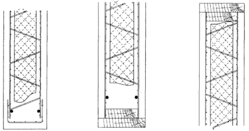
pattern approximately 18 inches wide and 6 inches high, advancing 3 to 6 inches every rotation as shown in figure 11. For corners the nozzle is held at an angle bisecting the comer to avoid trapping rebound as shown in figure 12. Scaffolding is used to allow nozzlemen access to surfaces as are extendable methods such as robotic arms and boom
trucks. Maintaining adequate moisture for the initial 7 days of curing helps prevent shrinkage cracking of the concrete and provisions such as sealant coatings, fogger
nozzles, and sprinklers may be used.
H t II.1 64 Uc:M I
13 6 I. I.
15-20 CI [ -9 IN I
Figure 11: Shotcrete placement on a flat surface
From ASCE Standard Practice for Shotcrete
I I
Figure 12: Shotcrete placement in corners
From ASCE Standard Practice for Shotcrete
For 3D panels one structural layer of shotcrete is first applied to the panels and
then a second finish layer with more attention given to a smooth consistent surface. Piano wires are also often set across the panels at the required thickness to guide the process.
Usually, a stucco finish layer is applied to the exterior but sometimes the concrete itself may be painted if no coarse aggregate is used and it is trowelled smooth. Cement based stucco may be used and painted or more advanced colored polymer based stuccos may be used for a significantly higher cost. Most residential projects use some sort of polymer based finish layer on the exterior which means either latex or elastomeric paint or polymer stucco. The resulting walls essentially never transmit moisture. A stucco finish may also be applied to the interior surface but most residential applications install inexpensive drywall with concrete nails. The drywall may be lifted slightly from the
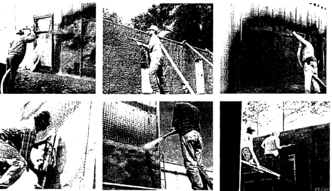
surface for running low voltage wires or using hollow wall anchors. Figure 13 shows shotcrete being applied to 3D panels.
C -' OZZLE /
/
*11 | ,.-,''zJ., Ea ->,1 "', -' -. t-, -. I - ' C -? , t I7
-~
I Ii . 1.^ js OX;;Figure 13: Shotcrete being applied to 3D panels
From http://www.3-dpanelworks.com
Concrete may also be applied to the panel by traditional pouring methods if poured at least 2 inches thick and encased by steel, aluminum, or wooden forms. The
manufacturer suggests such methods could be utilized to construct below grade foundations with the panels orienting horizontally in the ground. After the foundation trench is excavated, an initial bottom covering of concrete would be applied on top of whatever gravel and backfill is needed for drainage. The panel would then be inserted in the trench along with temporary supporting walls while concrete is pumped into the cavity. Supporting rebar for the vertical walls would also be integrated into the panel while the concrete is poured.
Similarly, the panels may be used to construct an insulating floor. An initial slab is poured on grade above the foundation with a self leveling concrete mix. 3D panels are then placed on the wet slab and floated by the insulating core while the reinforcing mesh is submerged in the concrete. Such a configuration is very useful for radiant heat flooring systems because it prevents heat loss through the floor and the heating tubes may be easily attached to the top supporting mesh before a final slab is laid down. While foundation and slab cracking can be problems with traditional concrete methods, the
geometry of thin reinforced concrete layers in 3D panels prevents cracking in the
foundation and slab just as for walls.
As previously mentioned, the panels may also be used across horizontal spans. Additional rebar is run along the bottom surface to absorb the tensile loads. The rebar is extended down along the supported walls as well. In such a situation, the panels must be supported while the shotcrete is placed and cured which generally limits frequent use. Figure 14 shows some examples of 3D panels being constructed across a span while figure 15 is an abbreviated version of the simple span load tables provided by the manufacturer which may be found in full in appendix A.
Figure 14: 3D panels used across a roof span
From http://www.tridipanel.com ~~~~~~~~~~~~~~~~~~~~~~~~~.. I 3-D PNEL CONFIGURATION LAYER THICKNESS n.1 COMP. I (TOP) 2.0 2.0 I ." 4 ... . -7-9 2-0 7.9 2.0 7.9 2,0 7.9 2.0 8.0 2.0 8.0 2.0 s.0 2.0 8.0 2.0 8.1 2.0 8.1 2.0 8.1 2.0 INSULATION CORE .. 4.0 4.0 A n 4.0. 0Y 4,0 4.0 4,0 4.0 4.0 4.0 4.0 4.0 4.0 TEN. (BOT.) 1.5 1.9 1 0 1.9 1.9 1.9 2.0 2.0 2.0 2.0 2.1 2.1 2.1 ..- ,. ... , I,, 1- . ADDITIONAL REINFORCING BAR SIZE NO. 3 3 .. 3... 3 3 4 4 4 4 5 5 6 5
5I
SPACING In. 0 24 1R~, , , 12 8 6 24 16 12 8 24 16 12 8 72 174 217 278 321 256 322 . 2., 3. 323 325 . ! 9 48 127 16 8 210 280 191 28S 281 275 283 .... i: 10 31 93 197 160 227 248 146 o20 248 213 250 ... : -^.1ALLOWABLE UNIFORM LOAD _PSF) SPAN Mt) I I 69 Q7 124 179 221 112 161 210 222 167 222 i!..!'..! 12 so50 73k 97 142 198 88 127 168 199 132 13 3 i .35 55_; 75 114 179 66 j1-01 136 180 105 199 180 i ;.' . '! 1 / "i1 14 24 l 68 92 163 80 10i 164 84 164 15 9. ....--". 44 74 149 37 63 90 149 66 149 16 33 59 128 26 Iso60 73 137 52 134 17 24 47 108 38 59 126 40 11ii3 126 In. Inl. 7.5 7.9 7 18 36 91 29 47 114 30 116 19 28 77 21 37 90 22 s 94 20 20 65 29 70 ... 67 74
Figure 15: Abbreviated simple span load tables for different 3D panel configurations From ICS 3D Panel Works
l
=
l _ . , . ,3.4 Properties of 3D panels
As noted previously, 3D panels are manufactured in many different
configurations. The insulating core may be expanded polystyrene of molded EPS and is
1.5, 2.5, or 4 inches thick. The reinforcing wire structure may be galvanized or not and is either 11 or 14 gauge wire. The width of the structure is 3, 3.5, 4, 4.5, or 5.5 inches. The truss wires are spaced at a density of either 5 or 9 per square foot. Table 5 shows some
common dimensional configurations often referred to in the associated literature.
Table 5. Geometry of commonly used 3D panel configurations
From ICS 3D Panel Works
gauge Overall Insulation RIM Truss density
width (in) width (in) width (in) (per sq. ft.)
Minimum panel 11 4.5 1.5 3 9
No. 14 gauge panel 14 5 2 3.5 5
Standard panel 11 5.5 2.5 4 9
Maximum panel 11 6 2.5 4.5 9
Two-hour panel 11 6.5 2.5 4 9
4 inch core 11 7-8 4 5.5 5
One of the concerns for materials in residential structures is fire resistance. Fire
resistances of standard panel configurations were determined from calculations and test
results. In the tests and calculations the panels were exposes to fire from both sides and the results are displayed in table 6. Trends in the results suggest the most influential factor is the width of the concrete. A full 2 inches on either side is required for 2 hour resistance.
Table 6. Fire resistance of different 3D panel configurations
From ICS 3D Panel Works
Carbonate Siliceous Aggregate Concrete Thickness Aggregate
Standard panel 1.5 hr 1 hr 1.5 in
Minimum panel 1.5 hr 1 hr 1.5 in
Maximum panel 1.75 hr 1.5 hr 1.75 in
Two-hour panel 2 hr 2 hr 2 in
The insulating capacity of the panels also depends on their exact configuration. In
most residential applications, the largest panel is used with a 4 inch insulating core and
5.5 inch wide reinforcing structure. Usually a 1.5 inch layer of concrete is used on either
side in these cases to make a 7 inch wide wall. Such a panel has a rating of R-18 if the
core is molded EPS and R-20 for the more expensive expanded polystyrene. Alternately,
a standard panel with a 2.5 inch molded EPS core has a rating of R- 1. The panel's
thermal mass varies with concrete thickness between 7 Btu per square foot per degree F for a 1.5 inch thick layer and 9.33 Btu per square foot per degree F for a 2 inch thick layer. These calculations assume a concrete density of 120 pounds per cubic foot. Another important consideration regarding the thermal performance of a 3D panel structure is that of thermal shorts. A large portion of the panels' insulating capacity comes from the fact that the only conducting elements passing between the exterior and interior envelope are the truss wires of very small diameter. When assembled, any spot
where insulation is removed all the way through will create a thermal short as the
concrete will conduct heat between the two envelopes. This fact should be considered when analyzing joint designs. Also, removing insulation for utilities will decrease the insulation rating even if some insulation still remains.
The thermodynamic performance of the panels was experimentally evaluated at the Granite Mountain Reserve built with 3D panels in the Mojave desert. The heat flux
and temperature distribution across a 3D wall was observed over many days. Figure 16
11} CtO l. a A= M~OC I C .D( 1MO( 2
00
.D i DFigure 16: Observed thermodynamic performance of 3D panels
From http://www.tridipanel.com
The panels also act as good acoustic insulators because of the two layers of concrete and have a sound transmission class of 35 without sheetrock and 40 with sheetrock.
As mentioned previously, 3D panels are often utilized because of their disaster resistance as showcased by the houses that survived hurricane Andrew. Builders using 3D panels in near the coasts of Georgia and Carolinas report designing buildings to meet the stringent 120 mile per hour wind rating of that area using only the 14 gauge panels. Also, 4 buildings made with 3D panels in the Mojave desert survived two earthquakes in
1992 called the Landers earthquakes. The earthquakes were 6.5 and 6.9 on the Richter scale and the epicenters were around 50 and 75 miles from the buildings. Engineers
inspecting the structures after the earthquakes reported no damage to superstructures or
foundations.5
3.5 Costs associated with 3D panel construction
Table 7 shows an average price break-down of building with 3D panels. The numbers are based on the previously described surveys in Concrete Homebuilding
Systems. The numbers presented are an average of those reported which varied by more
than 1 dollar per square foot in each direction. Most of the builders were traditional contractors beginning to use 3D panels. The houses built using these methods ended up
being more expensive than equivalent frame houses and the performance provided by the
panels justified the additional cost. The numbers shown give a good sense of the relative
cost of these panels but could certainly be reduced by streamlining construction methods
and by designing specifically for 3D panels.
Table 7. Average reported costs for 3D exterior walls per square foot wall area
From Concrete Homebuilding Systems, VanderWerf and Munsell
Component
Structure and insulation
5.5 inch panels with EPS insulation Cover mesh and wire ties
Concrete Misc. lumber
Panel assembly labor
Shotcrete and finishing labor
Rough finish both sides
Smooth finish both sides Subtotal
Cost per square foot wall area
2.15 0.25 1.00 0.25 2.25 1.05- 1.25 1.05 1.25 $6.95 - 7.15
Exterior siding andfinish (material and labor) Elastomeric paint
PC stucco and paint PB stucco (colored)
Interiorfinish (materials and labor) Paint only
Sheetrock, furring and paint Total $0.80 - 2.50 0.80 1.00 2.50 $0.80- 1.50 0.80 1.50 $8.55- 11.15
3.6 Summary of benefits of 3D panel construction
3D panels are certainly an appealing construction method for certain residential
Table 8. Benefits of 3D panels as cited by the manufacturer
From http://www.3-dpanelworks.com
Reduces Construction Time: Allows erection of walls in considerable less time than
other existing methods of construction. A standard 4' X 8' 3-D panel weighs only 38 pounds and can be positioned and attached to adjacent panels by one man in a manner of minutes.
Reduces The Need For Heavy Equipment At The Job Site: Handling and erection of
3-D panels arc very simple and can be accomplished with vary little equipment and a minimum of manpower.
Fewer Trades On Job: The building system requires fewer different trades on the job
site since insulation is included in the panels, unskilled labor can install, and the concrete application can be brought to a desired finish. Along with the simplicity of a "systems wall", bookkeeping is made easier as less checks have to be issued and paper work is reduced.
Greater Structural Integrity: The 3-D panel system, erected and shotcreted, gives the
owner a continuously reinforced, insulated wall that will accept a variety of interior and exterior finishes, including its natural texture. This monolithic structure provides an extraordinary strength-to-weight relationship.
Offers Design Flexibility: The 3-D system allows the architect/engineer to design for
various wind loads and seismic conditions. The Council of American Building Officials which includes BOCA, ICBO, and SBCCI approved the 3-D panel system and issued Report No. NER-454. The 3-D system can be used in single-story or multi-story
facilities. ICS 3-D Panel Works, Inc. is available to assist you with design and estimating details.
Superior Fire Resistance: With 1.5 inches of concrete applied to both sides of 3-D
panels, a fire rating of 1.5 hours is obtained; 2 inches gives a 2 hour rating. Ratings can be increased with the increase of concrete or other coatings and finishes.
Lower Maintenance costs: The 3-D system, which yields a concrete structure, accepts a
variety of internal and external Finishes to minimize maintenance requirements.
Excellent Sound Attenuation Characteristics: Due to its double shell construction, the
concrete/polystyrene/concrete sandwich panel configuration minimizes sound transmission.
Earlier Completion Offers Earlier Occupancy: Ease of installation and overall
reduction of labor required provides the owner earlier occupancy and reduces total capital investment.
Excellent Thermal Insulation: The standard 3-D panel has modified expanded
Simplified Utility Installation: Space between mesh and insulation allows for easy
placement of electrical conduit or piping prior to the application of concrete.
Environmentally Safe: Wire used in the production of the 3-D panel is manufactured
from recycled steel. The process used to make polystyrene does not involve CFC's which were phased out in 1989. Our forests are not threatened by this system since it uses steel, polystyrene and concrete, ..twenty first century technology - today.
3.7 Code Compliance and Verification
Responsible use of 3D panels in construction has been verified numerous times
using a variety of methods since they were developed in the 80s. In addition to analytical
methods, experimental testing at a number of different facilities has confirmed the behavior expected from 3D panels. The construction processes used with 3D panels have also been outlined according to various industry guidelines. A summary of the
qualifications met by the panels is presented in a report from the National Evaluation Services (NER-454). The report verifies manufacturer claims based on submitted test
evidence and analysis. This report is provided in appendix B. Briefly, the panels have
been proven to be effective for both residential and commercial construction and when constructed properly, conform to all relevant codes. In practice, the manufacturer provides a lot of documentation and assistance to builders submitting proposals to local building departments because the product is new.
4.0 Proposed Modular House Design Using 3D panels
A modular housing system designed to be constructed primarily with 3D panels is presented in the following section. While most residential applications of 3D panels integrate the panels with traditional methods and designs, the processes and details for this new design were developed independently of such constraints. In order to produce a design with maximum economy, it was assumed that a commercial application of the design would be done in large enough numbers that a specialized dedicated labor force could be trained in the relevant methods. It was also assumed that an additional
manufacturing facility would be possible in order to process relevant materials. This process is a large deviation from present practice for concrete homebuilding systems but could be viable under the right circumstances.
4.1 Form and Modularity
The basic structure of the design has a hexagonal footprint with a pitched roof
along two opposing vertices as shown in Figure 1. While this shape is a diversion from
the traditional square based design used in most houses, it has associated benefits that
will become apparent. 374 square foot hexagonal units are combined as desired in a modular fashion as shown also in Figure 17.
Figure 17: Basic structure and modularity of proposed house design
The ability to freely scale a house with standard building units is beneficial when
it comes to construction economy and allows for many different floor plans. Each unit may be used as one large room or may be subdivided if needed using basic non-structural
methods. A 5 unit floor plan is shown in figure 18. A 5 unit building has 1870 square feet of floor area, 2640 square feet of wall area before windows and doors are inserted.