HAL Id: inria-00587151
https://hal.inria.fr/inria-00587151
Submitted on 20 Apr 2011
HAL is a multi-disciplinary open access
archive for the deposit and dissemination of sci-entific research documents, whether they are pub-lished or not. The documents may come from teaching and research institutions in France or abroad, or from public or private research centers.
L’archive ouverte pluridisciplinaire HAL, est destinée au dépôt et à la diffusion de documents scientifiques de niveau recherche, publiés ou non, émanant des établissements d’enseignement et de recherche français ou étrangers, des laboratoires publics ou privés.
Logical time @ work: the RT-Simex project
Julien Deantoni, Frédéric Mallet, Charles André, Frédéric Thomas
To cite this version:
Julien Deantoni, Frédéric Mallet, Charles André, Frédéric Thomas. Logical time @ work: the RT-Simex project. Sophia Antipolis Formal Approach, Apr 2011, Sophia, France. �inria-00587151�
Logical Time @ Work : The RT-Simex project
Julien DeAntoni, Frédéric Mallet, Charles André Frédéric Thomas
EPI Aoste, INRIA Méditerranée & UMR CNRS I3S Obeo, Model Driven Company
& Université de Nice Sophia Antipolis 2 route de la Noue, BP 76
Sophia Antipolis, FRANCE 91193 Gif-Sur-Yvette
{firstname.surname}@sophia.inria.fr [email protected]
Abstract—This paper overviews the benefits of using logical
time in the context of the RT-Simex project. We focus on the use of logical time to, first, graphically specify the functional and extra-functional system requirements; second, to verify that an execution is correct with regards to the requirements. The system requirements are expressed by using the UML MARTE profile conjointly with CCSL, its formal and tooled companion language.
Keywords-Logical Time; MARTE, MDE, RT-Simex
I. CONTEXT
RT-Simex1 is an ANR project whose global aim is the
improvement of methods and tools for embedded software design. It focuses on techniques to link together specifications and observations of functional and extra-functional behavior of real time and embedded systems. We formally defined the required behaviors in a UML MARTE model [5,6].
The MARTE specification gives, in its Time sub-profile, a way to deal with logical and multiform time. Logical time relies on a relaxed form of time that supports causal (untimed) and chronological (timed) relationships between some events. In logical time, the ordering of events (causal relationships) is essential, albeit often partial. Multiform time supports metrics involving several time bases, not just the physical time (e.g., a car must stop before 100 ms or 2 m, which ever occur first). If needed, a metric to measure the distance in time between two instants may be added. The Time sub-profiles deals with logical time via Clocks. A clock is an ordered set of instants. MARTE also introduces clock constraints that specify relations between instants. A (logical) clock represents an event, its instants stand for the occurrences of the event, and an instant relation models a dependency between event occurrences. The Clock Constraint Specification Language (CCSL) is a model-based declarative language that allows handling of logical time and the associated constraints. As such, a CCSL specification characterizes the set of possible interactions and is suitable to describe the functional and real-time behavior of a system. CCSL has a formal semantics [1] that can be exploited to process a correct execution, if any, or to determine whether a candidate execution is valid (i.e., satisfies all the clock constraints) or not.
In this context, the first contribution is an easy, graphical and intuitive way to manipulate logical time for the specification of functional and real-time requirements of a system. It consists in a set of graphical representations, which correspond to classical patterns identified in the distributed real-time and embedded system domain. The graphical application of these patterns is done via a view point in the Obeo Designer tool2, which
automatically augments the MARTE model with the necessary clocks and constraints. The model can then be 1 http://www.rtsimex.org
simulated in TimeSquare to better apprehend or debug the specification. Once well specified, the system is then implemented (either automatically or not). The implementation is then automatically instrumented to produces traces in the OTF (Open Trace Format) format [3 ], which correspond to an ordered set of the events of importance with regards to the specification. The conformity of this trace can then be checked against the requirements.
After a presentation of some classical real-time requirement patterns, their formal specification is described. Then, the graphical application as well as the checking of an execution are over-viewed.
II. REAL-TIME REQUIREMENT PATTERNS
In this section we describe some of the requirement patterns needed in the real-time embedded system domain (e.g., periodicity, jitter, deadline, burst, communication latency). These constraints usually refer specifically to the physical time. In the context of RT-Simex, the proposed patterns extend these common notions to logical time. For instance, beyond stating that a task is periodic with a period of 3 ms, we can also state that a task is three times faster than another task, itself linked or not to the physical time. These patterns give relations between some event occurrences. We only describe here the Duration and the perdiodicity patterns.
Duration : An event occurrence must occurs before another occurrence that represent the maximum duration. It must also occurs after en occurrence that represents the minimum duration. This a very abstract pattern which can be refined into two various constraints depending on the context of use (e.g. deadline, response time, communication time, ...). A duration states that the duration between a tbegin and a tendevent occurrences may be
bigger than a minimal time min and lower than a maximum
time max. tend[i] is the ith occurrence of the tend event and
tbegin[i], the ith occurrence of the tbegin event:
i, min < | tend[i] – tbegin[i] | < max
The min and max parameters can then be specified as a
number of occurrences of a specific event, as a specific combination of event as well as in physical time. To specify a communication time, tend and tbegin events can
respectively represent the receiving and the sending of an event.
Periodicity : An event e, whose the ith occurrence is
denoted e[i], occurs periodically signifies that the distance between two successive occurrences is equal to a constant:
i, e[i+1] – e[i] = period. Due to possible imperfection in the event generation, the period can be subject to a variation around its perfect value. This value is denoted
jitter and represents the maximum difference between the
perfect and the actual distance between two successive event occurrences: i, || e[i+1] – e[i] | - period | < jitter
2 http://www.obeo.fr/pages/obeo-designer/use-case-embedded/fr
III. CCSL AND MARTE FORPATTERNDESCRIPTION
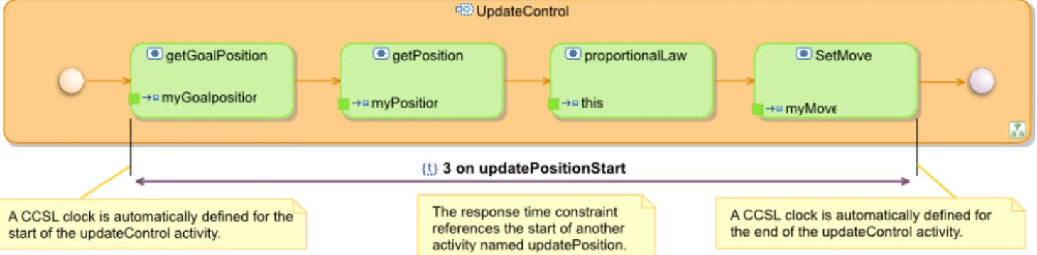
The MARTE Time model describes the event as logical time entities via the concept of Clock. The instants of these clocks correspond to the event occurrences. CCSL is suitable to describe constraints between some clocks, and therefore between their instants. It is used to give a formal semantics to the identified patterns. The following section presents a specific duration: the response time and its graphical application on an activity diagram (see figure 1 the specification of a periodic activation on the top left, the specification of a responsive time and the specification of a deadline on the bottom).
A. Specification: Responsive Time and its application
We show the internal CCSL definition of the
ResponseTime pattern and explain how it is applied on the
model by using the graphical representation.
The ResponseTime pattern is applicable on an action. The parameter of such pattern are three clocks and two integers. The first clock (named begin) represents the
beginning of the action, the second clock (end) represents the end of the action. The third clock, named ref, is the
reference clock on which the distance between the begin
and the end of the action is evaluated. This is a clock and consequently can be either related to physical time (for instance representing the ms), or logical (for instance representing the tick of a processor). This is a major benefits of using logical time. It allows to express the constraint of the system as relation between the events of the system rather than specifying them as function of the physical time. For instance, one could specify that an action must be finished before the next activation of a specific task. Latter, when all platforms parameters are known, the activation of the task can be mapped on the physical time so that logical constraints are always true and take the physical constraint into account without any modifications. The bcrt and wcrt integers represent
respectively the best and the worst case responsive time.
def ResponsiveTime(begin:Clock,end:Clock,ref:Clock,bcrt:int,wcrt:int){ end precedes (begin delayedFor (wcrt ) on ref) || (begin delayedFor (bcrt) on ref) precedes end }
All the patterns are grouped together in a library that encapsulates specific composition of the CCSL kernel operators (on which the semantics is formally defined [1]). It can then be instantiated easier without a needed for a deep knowledge of CCSL. The application on a UML model is realized by using Obeo Designer . It allows the definition of a specific view point over an existing model [4]. The add of such graphical representation automatically add the needed element in the MARTE model and instantiates the CCSL patterns. Figure 1 show a responsive
time constraint between the begin of the GetPosition action
and the end of the proportionalLaw action. It is applied by selecting responsive time in a palette and by clicking successively on the action for which begin and then end are considered. Then, the user can textually specify the bcrt
and the wcrt. He is then assisted to choose the ref clock
(here named ms). When doing this, the tool automatically generates the necessary clocks if they do not already exist and instantiate the responsive pattern called inside a
TimedConstraints as specified in the MARTE Time profile.
The model can now be simulated and or animated in the TimeSquare tool [2]. Moreover, while the view point is specific to real time constraint and assist the user in the definition of the requirements, it can be opened by any MARTE compliant tool.
B. Verification: checking an execution trace
Once all requirements added to the model, it is implemented in a specific language. It is important to check that the implementation satisfies the requirements. Consequently, we propose to instrument the implementation to produce an execution trace in the OTF format [3]. This instrumentation provides an ordered set of event occurrences, which represents a specific execution of the system. The instrumentation is parametrized so that the execution trace contains only the events associated to clock and so to requirements in the model. The OTF file is then translated into a trace model where events are associated to clocks. Finally, this trace model is used in input of TimeSquare and simulated conjointly to the CCSL specification to detect any constraint violation. If a constraint violation is detected, a message that specify the violated constraints and the timestamps where the violation occurred is given.
IV. REFERENCES
[1] André, Charles.: Syntax and Semantics of the Clock Constraint Specification Language (CCSL). Research report, INRIA and University of Nice (May 2009)
[2] DeAntoni J., Mallet F., André C., and Ferrero B.. TimeSquare, on the formal execution of UML and DSL models. 4th Int. School on MDD for Distributed, Realtime, Embedded Systems, April 2009. [3] A Knupfer, R Brendel, H Brunst, H Mix, WE – Introducing the
Open Trace Format- LNCS, 2006 – Springer
[4] F. Thomas and E.Juliot – Towards a Viewpoint-Based Framework for Reactive Systems Modeling – Complex Systems Design & Management (CSDM) 2010, Industrial session, 2010.
[5] OMG: Unified Modeling Language, Superstructure. (November 2007) Version 2.1.2 formal/2007-11-02.
[6] The ProMARTE Consortium: UML Profile for MARTE, beta 2. Object Management Group. (June 2008) OMG document number: ptc/08-06-08.