DOI: 10.1007/s00339-004-3100-5
Rapi
d
communi
cati
on
Materials Science & Processing
b. luki´c1 j.w. seo1 e. couteau1 k. lee1 s. gradeˇcak2 r. berkecz3 k. hernadi3 s. delpeux4 t. cacciaguerra4 f. b´eguin4 a. fonseca5 j.b. nagy5 g. cs ´anyi6 a. kis1 a.j. kulik1 l. forr ´o1,u
Elastic modulus
of multi-walled carbon nanotubes
produced by catalytic chemical
vapour deposition
1Institut de la Physique de la Matière Complexe, Ecole Polytechnique F´ed´erale de Lausanne, 1015 Lausanne, Switzerland
2Centre Interdisciplinaire de Microscopie Electronique,
Ecole Polytechnique F´ed´erale de Lausanne, 1015 Lausanne, Switzerland 3Department of Applied and Environmental Chemistry, University of Szeged,
Rerrich B´ela t´er 1, 6720 Szeged, Hungary
4CRMD, CNRS-Universit´e, 1B rue de la F´erollerie, 45071 Orl´eans Cedex 02, France 5Facult´es Universitaires Notre-Dame de la Paix, 61 rue de Bruxelles, 5000 Namur, Belgium 6TCM Group, Cavendish Laboratory, University of Cambridge, Madingley Road,
Cambridge CB3 OHE, UK
Received: 7 June 2004/Accepted: 19 October 2004
Published online: 15 December 2004 • © Springer-Verlag 2004
ABSTRACTCarbon nanotubes (CNTs) are ideal structures for use as reinforcement fibres in composite materials, due to their extraordinary mechanical properties, in particular high Young’s modulus (E∼ 1 TPa). Usually the high value of E is taken as granted for all types of carbon CNTs. Here we demonstrate that multi-walled carbon nanotubes (MWCNTs) produced by catalytic chemical vapour deposition (CCVD) have low moduli (E< 100 GPa) independently of their growth conditions. We attribute this to the presence of structural defects. Additional high-temperature an-nealing failed to improve the mechanical properties. This study urges a better control of the growth process in order to obtain high strength CCVD grown MWCNTs suitable for reinforcement in large-scale industrial applications.
PACS62.25.+g; 68.37.Ps; 81.15.Gh
1 Introduction
Carbon nanotubes [1] (CNTs) are of interest both from a fundamen-tal point of view and for future appli-cations. Apart from their remarkable electronic and thermal properties [2, 3], they also show unique mechanical char-acteristics with high Young’s modulus (∼ 1 TPa) and breaking strength com-bined with low density [4–10]. As such, they are ideal candidates as reinforce-ment fibres in composite materials. The method of catalytic chemical vapour deposition (CCVD) [11] is the most promising in terms of large-scale pro-duction due to the possibility to up-scale both production and purification methods [12]. This process involves high-temperature (600◦C to 1200◦C) u Fax: +41-21-693-4470, E-mail: [email protected]
catalytic decomposition of hydrocar-bons on metallic catalyst particles. The common view holds that CNTs grow by the extrusion of carbon dissolved in a catalyst particle that is oversaturated in carbon at one part of the surface [13]. Production is usually chosen to give a high yield of CNTs of a specific type, while the value of Young’s modulus is assumed to be ∼ 1 TPa, the same as for multi-walled and single-walled car-bon nanotubes (MWCNTs and SWC-NTs) grown by arc discharge and laser ablation, respectively [5, 10]. But, the very first study of Salvetat et al. [7] has shown that CCVD-grown CNTs have poor mechanical properties with Young’s modulus in the range of 10 to 50 GPa[7] due to the misalignment of graphitic planes and the tube axis.
Here we report a systematic study of the elastic measurements of CCVD-grown MWCNTs produced under var-ious growth conditions. The observed wall structure is significantly better than in the previous study – no mis-alignment and better graphitization – but all MWCNTs show Young’s mod-ulus lower than 100 GPa. An attempt to improve their structure by high-temperature annealing failed to improve their elastic property. This study sug-gests that MWCNTs produced by the CCVD method have a large number of defects, which are difficult to recuper-ate from afterwards. There is clearly a need to optimize the growth conditions in order to produce high strength CCVD grown CNTs. 2 Experimental 2.1 CCVD production and high-temperature annealing of MWCNTs Four batches of MWCNTs were prepared by the CCVD method in different laboratories. All used acety-lene as the carbon source. The main variation was in the choice of support material for catalytic particles, which can influence strongly the CNTs’ char-acteristics [14].
Here we give a short description with details given as noted: batch I. MWCNTs were produced by catalytic decomposition of acetylene on Co/NaY zeolite catalyst in the temperature range
ition of acetylene at 600◦C on a CoxMg(1−x)Osolid solution contain-ing 40 wt. % of CoO. Silica was used as a support [16, 17]; batch III. Li2CO3-supported Fe/Co catalysts were pre-pared from acetone and acetylene was decomposed at 700◦C; batch IV. Acety-lene was decomposed on Co–Fe par-ticles on a CaCO3 support (5 wt. % of Co, Fe) at 720◦C[18].
MWCNTs from batch II were an-nealed at temperatures of 1200◦C, 1700◦C, 2100◦Cand 2400◦C. Anneal-ing was realized in a graphitization fur-nace under an argon flow of 3 l/min; the heating rate was 13◦C/min with 15 min of resident time at the desired tempera-ture.
2.2 Structural and mechanical characterization
Transmission electron micro-scopy (TEM) characterization was car-ried out using a Philips CM300 FEG mi-croscope operating at 300 kV. For TEM sample preparation, CNTs were dis-persed in isopropanol and sonicated for 5 min. A droplet of suspension was put on a Cu TEM grid with a holey C film.
For atomic force microscopy (AFM) measurements, MWCNTs were dis-persed in ethanol by sonication for 5 to 10 minand a droplet of suspension was placed over a polished alumina mem-brane (Whatman Anodisc, nominal pore diameter of 200 nm) itself placed on fil-ter paper and then filtrated for a few minutes. Measurements for some tubes from batch II and for all tubes from
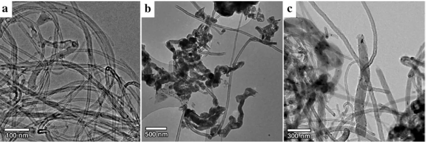
FIGURE 1 Characteristic low-resolution TEM images of CCVD-grown CNTs from a batch I, b batch III, c batch IV. Scales are different due to differences
in the size of MWCNTs
1µm in diameter. AFM images were taken in contact mode operating in air (Autoprobe CP or Autoprobe M5, Park Scientific Instruments), varying the load from image to image. Sharpened non-coated or gold-non-coated Si3N4cantilevers (ThermoMicroscopes) with force con-stant 0.01–0.1 N m−1 were used. The force constant was calibrated prior to the measurement [19].
3 Results and discussion 3.1 Structure studied
by transmission electron microscopy (TEM)
Figure 1 displays character-istic low-magnification TEM images of the CCVD-grown nanotubes of batches I, III and IV, while for batch II they can be found elsewhere [20]. CNTs from all batches are preferentially curved on the length scale of several hundred nanometres, except for batch III where MWCNTs are straight on a micron scale. This demonstrates the importance of the choice of the support, which is the principal difference in preparation between batches III and IV. Graphitic sheets aligned parallel to the tube axis can be seen in the high-resolution TEM images of Fig. 2. The wall structure of these tubes is very similar to the wall structure of MWCNTs grown by the arc-discharge method. MWCNTs vary in outer diameter within one batch as estimated by TEM. Those from batch I have diameters in the range of 20 to 30 nm[15], batch II have 10 to 15 nm,
IV show somewhat bigger variation – from 30 to 80 nm for the outer diameter. MWCNTs from batch III have an outer-diameter distribution of 58± 12 nm and an exceptionally large inner diameter that can reach 35 nm (Fig. 2b).
3.2 Mechanical properties studied by atomic force microscopy (AFM)
When imaged by AFM, we could observe rings of MWCNTs on the alumina surface in the case of batch I, as can be seen in Fig. 3a. They are most likely formed by the surface tension of the air bubbles generated by the soni-cation of the ethanol/nanotube suspen-sion. After placement of a droplet of the suspension on the substrate and sub-sequent evaporation of the solvent, the nanotube ring is stabilized by van der Waals interaction on the surface [21, 22]. This observation already suggests a weak mechanical strength of the CCVD-grown MWCNTs, since coiling involves significant strain energy due to the in-creased curvature.
One method for measuring the elas-tic modulus of a CNT is to clamp the nanotube at each end and to measure its vertical deflection versus the force ap-plied at a point midway along its length. Here, we measured Young’s modulus E by AFM using a method described previously [23]. After sample prepar-ation, nanotubes occasionally lie over a hole with a short section of their en-tire length, whereas the major part of the nanotube is still in contact with
FIGURE 2 Characteristic high-resolution TEM images with the same marks as in Fig. 1. Scales are different due to differences in the diameter of MWCNTs. Only one side for MWCNTs from batch III (b) is shown since the inner channel is too big (∼ 35 nm). The inner channel is on the top
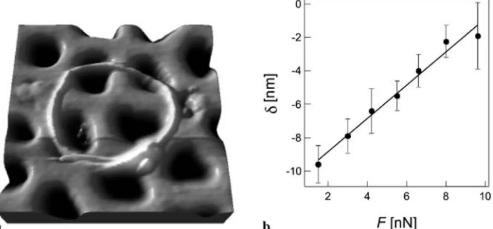
FIGURE 3 (a) Three-dimensional rendering of an AFM image showing MWCNT ring structure
(batch I) deposited on the alumina membrane after solvent evaporation (image area∼ 1 µm2). (b)
De-flection versus applied force for a MWCNT measured by AFM. The deDe-flection is measured on the suspended portion of the nanotube over the hole on which the AFM cantilever applies the force. For forces up to 10 nN, the response to deflection is linear. The line is a linear regression fit of experimental data, and its inverse value F/δ is used to calculate Young’s modulus
the membrane surface. During scan-ning with the AFM tip, the suspended nanotube bends and the vertical deflec-tion in the middleδ can be directly de-duced from an AFM image (Fig. 3b). The height of the nanotube was derived from a part that lies on the flat mem-brane surface and was set equal to the diameter D. This estimate is more pre-cise than the measured width due to the tip-convolution effect. For the sus-pended length L we take the pore width on sites just next to the nanotube. Due to irregular pore shape, the error in L is about 10%. Using simple beam me-chanics [24], the Young’s modulus E is estimated from E= FL3/δαI, where α = 192 for a clamped beam, F is the applied force varying from image to image and I = π(D4− D4
i)/64, Di be-ing the inner radius of a MWCNT. By neglecting Di (< 5 nm) we
underesti-mate the values for E, but that error is still small compared to the error made by the determination of L, which con-tributes most to the error in E. Even for the case of MWCNTs from batch III, which have large Di, underestimation can reach∼ 20%.
Calculation of E is based on the assumption of the nanotube being per-fectly clamped to the alumina mem-brane. Adhesion depends on the real contact surface between the nanotube and the substrate, and if the contact sur-face is small (either due to the bent structure or an inhomogeneous surface) the nanotubes move. MWCNTs de-posited on a SiO2surface can be moved with an AFM tip with normal forces of 10–50 nN [25], and we observed sev-eral such events in our samples, but with forces below 10 nN. However, none of the nanotubes presented above moved
from one AFM image to another, that is to say, each point in the force–deflection curve was measured for the same nano-tube position over the hole. The inves-tigated force range reached maximally 11 nN.
A summary of mechanical measure-ments is shown in Fig. 4. For the sake of comparison, results of the Young’s mod-uli of MWCNTs grown by arc discharge from previous work [7] are included. Average values of E for each batch of MWCNTs are grouped in three bins per decade so that the bins have equal range on a logarithmic scale. Such a represen-tation is used to capture data that span several orders of magnitude. Values for batches I and II follow a Gaussian-like distribution, while other batches prob-ably follow the same pattern, although this cannot be readily established due to the smaller number of data points. Nev-ertheless, CCVD-grown MWCNTs evi-dently have a low Young’s modulus for all four batches, with a distribution of values in the range between 1 GPa and 100 GPa.
3.3 Origin of low Young’s modulus
Our results are in agreement with the values reported in the first study of CCVD-grown MWCNTs, but it has to be noted that in that study only five MWCNTs from one batch were measured [7]. Such low values were explained by misalignment of the graphitic planes with the tube axis, where planes and axis enclosed an angle ϕ = 30◦C. As a rough approximation, the measurement can be considered as the Young’s modulus of a single
graph-three bins per decade presented in a way to make the range of the bins equal on logarithmic scales. Values for arc-discharge-grown MWCNTs [7] are shown separately (‘arc-discharge grown MWCNTs’)
ite crystal measured in the direction that includes an angle of ϕ with the hexagonal axis. Variation of the elas-tic modulus with ϕ is then given by 1/E = S11(1 − γ2)2+ S33γ4+ (2S13+ S44)γ2(1 − γ2), where S
ij are elastic compliances of bulk graphite andγ = sin(ϕ) [26]. As can be seen in Fig. 2, the MWCNTs in this study showed better structure in general: batch III MWC-NTs reveal ϕ ∼ 10◦C, which gives E∼ 150 GPa; MWCNTs from batches I and IV have ϕ ∼ 0◦C, which gives E= 1/S11∼ 1000 GPa [26]. This cal-culation shows that misalignment alone cannot explain the obtained low values of Young’s modulus, and their origin must lie elsewhere.
It is rather difficult to determine the presence of structural defects and their distribution in the structure of MWC-NTs. TEM can determine misalignment of graphitic sheets or poor graphitiza-tion, but not other defects like vacan-cies, interstitials of carbon or atoms of the catalyst, carboxyl groups that are at-tached to the walls during purification, or edge dislocations. Point defects in-side planes, like vacancies and inter-stitials, should not significantly influ-ence mechanical properties, unless their density is increased sufficiently.
In order to estimate to what extent vacancies reduce the Young’s modu-lus of CNTs, we performed theoretical calculations. We used ab initio plane wave density functional theory [27] in the GGA approximation [28] (as im-plemented in the CASTEP code [29]).
All calculations were done on the(5, 5) armchair tube, using a 100-atom unit cell, 8 K points along the tube axis, 336-eV plane-wave cut-off and ultra-soft pseudopotentials. For each struc-ture all coordinates were optimized. To get the Young’s modulus, the unit cell was stretched slightly and the inter-nal coordinates were re-optimized. The pristine tube was found to have a mod-ulus of 0.85 TPa. Both a single vacancy and a divacancy oriented perpendicular to the tube axis reduced this to around 0.75 TPa. The main uncertainty in the absolute (but not the relative) magni-tudes of these results is due to the trans-lation of the energy of stretching in units of pressure, which was done using a SWCNT bundle with a triangular lat-tice constant of 10 Å. Another study per-formed on a larger SWCNT showed an even smaller effect: removal of 4.7% of the SWCNT’s surface decreases bend-ing rigidity by only 24% [30]. In conclu-sion, vacancies cannot explain the order of magnitude decrease of E from the op-timal value of 1 TPa.
Non-planar defects could influence mechanical properties in a more sig-nificant way. Intuitively, when Young’s modulus is estimated from elongation due to the tensile strength, edge dis-locations parallel to the tube axis will not influence it. In contrast, when esti-mated from bending rigidity, as in our experiment, the effect of the disloca-tions should be more profound. Unfor-tunately, simulations show that they are difficult to observe with TEM when they
direction) [31].
3.4 High-temperature annealing of MWCNTs
In the case of micrometre-sized carbon tubes, the annealing at tem-peratures from 1600 to 2400◦Cchanged the structure from disordered amorph-ous carbon to a more ordered and pref-erentially oriented graphitic phase, as studied by TEM, Raman spectroscopy and X-ray powder diffraction [32]. Sev-eral other TEM and thermogravimetric studies [20, 33, 34] have suggested the same positive effect of annealing on the CCVD-grown MWCNTs.
We have employed this strategy to improve mechanical properties of MWCNTs from batch II. Lack of graphi-tization or disordered graphitic layers are reasons for low values in this batch, which is not surprising since they are made using a similar production tech-nique and conditions as in the pre-vious study [7]. Exposing MWCNTs to a higher temperature might elim-inate at least partly the defects that are present in the wall structure after the production. Since energies in the order of eV are required for migration of vacancies [35] and interstitials [36], temperatures around 2000◦C increase the migration probability by several orders of magnitude and may conse-quently lead to their recombination and subsequent annihilation in the struc-ture. High-resolution TEM studies of MWCNTs irradiated by a large flux of electrons show possible pathways for improvements in the wall structure when there is sufficient energy: fusion of the round-shaped graphene into the walls or rearrangement of the graphene layers [37].
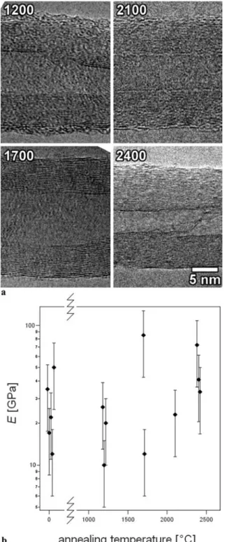
Annealing was performed on MWC-NTs from batch II in argon atmosphere at temperatures of 1200◦C, 1700◦C, 2100◦C and 2400◦C. Representative TEM images of MWCNTs annealed at selected temperatures (TEM images of pristine MWCNTs can be found else-where [20]) are shown in Fig. 5a. The wall structure seems to improve with higher-temperature treatments, but this is not reflected in the values of Young’s modulus shown in Fig. 5b. All the meas-urements for annealed tubes at different temperatures show that E does not reach
FIGURE 5 (a) Characteristic TEM images of MWCNTs (batch II) annealed at different tempera-tures (in◦C). (b) Young’s mod-ulus E for pristine [7] MWC-NTs and annealed at 1200, 1700, 2100 and 2400◦C. Values for the same annealing temperature are shifted for 40◦C to ease the view
the value of 1 TPa and clearly stays below 100 GPa. We do see a small in-crease in modulus between MWCNTs annealed at 1200◦C and 2400◦C, but for a quantitative analysis more statis-tics are needed. Since all our measure-ments give low values for E, we con-clude that annealing cannot annihilate the defects present in the structure and as a consequence cannot improve the mechanical properties of CCVD-grown MWCNTs.
4 Conclusion
We have shown that defects in the structure of MWCNTs produced by the CCVD method weaken the elas-tic modulus and they cannot be fully eliminated by high-temperature anneal-ing up to 2400◦C. Furthermore, none of the proposed production recipes give MWCNTs of sufficient mechanical strength, even though apparently they show good structural quality. The
dens-ity of defects is rather unknown, and more detailed theoretical and experi-mental studies have to be done in order to estimate the critical density required to lower the Young’s modulus of CCVD-grown MWCNTs significantly. Further-more, one needs to explain the differ-ence between these values and those obtained by theoretical studies [38] and measurements on MWCNTs grown by arc-discharge or laser-ablation methods. The growth mechanism for the tubes produced by these techniques is very different compared to CCVD-grown tubes. In particular, the synthesis tem-perature reaches more than 3000◦C, in contrast to CCVD where a temperature below 1000◦Cis applied.
Our results suggest that more con-trol is needed in the growth process of MWCNTs produced by CCVD. Pos-sible improvements include cleaner at-mosphere in the furnace, well-defined geometry and size of the catalyst par-ticles, as well as suitable orientations between the crystallographic planes of the catalyst particle and the sup-port. Here we used only acetylene; other carbon sources might give differ-ent results. Comparative studies where only one production parameter is var-ied [14] or in situ observations of the MWCNT growth [39] could lead to a better understanding of the growth process.
Since the CCVD method is the most promising in terms of large-scale pro-duction, it is imperative to find bet-ter production conditions which could make MWCNTs with better structural quality and with higher modulus. At the present stage, they do not give the high reinforcement as expected from CNTs. Alternatively, CCVD-grown single-walled or double-single-walled nanotubes should be used for composites, where annealing is more efficient due to the lower initial number of structural defects.
ACKNOWLEDGEMENTS We thank
G. Beney (EPFL) for polishing alumina mem-branes, Prof. J. Brugger (EPFL) for Si3N4
mi-crofabricated membranes, J.-P. Salvetat (CNRS Orl´eans) for discussions as well as Centre In-terdisciplinaire de Microscopie Electronique (CIME) at EPFL for access to electron micro-scopes and technical support. The study was performed within the TMR network ‘Nanocomp’ of the European Community and supported in part by the Swiss National Science Foundation and its NCCR ‘Nanoscale Science’ program.
tion of Hungary (OTKA T046491) for financial support.
REFERENCES
1 S. Iijima: Nature 354, 56 (1991)
2 J.W.G. Wildoer, L.C. Venema, A.G. Rinzler, R.E. Smalley, C. Dekker: Nature 391, 59 (1998)
3 P. Kim, L. Shi, A. Majumdar, P.L. McEuen: Phys. Rev. Lett. 87, 215 502 (2001) 4 M.M.J. Treacy, T.W. Ebbesen, J.M. Gibson:
Nature 381, 678 (1996)
5 E.W. Wong, P.E. Sheehan, C.M. Lieber: Sci-ence 277, 1971 (1997)
6 M.R. Falvo, G.J. Clary, R.M. Taylor, V. Chi, F.P. Brooks, S. Washburn: Nature 389, 582 (1997)
7 J.P. Salvetat, A.J. Kulik, J.M. Bonard, G.A.D. Briggs, T. Stockli, K. Metenier, S. Bonnamy, F. Beguin, N.B. Burnham, L. Forro: Adv. Mater. 11, 161 (1999) 8 P. Poncharal, Z.L. Wang, D. Ugarte, W.A. de
Heer: Science 283, 1513 (1999)
9 M.F. Yu, O. Lourie, M.J. Dyer, K. Moloni, T.F. Kelly, R.S. Ruoff: Science 287, 637 (2000)
10 M.F. Yu, B.S. Files, S. Arepalli, R.S. Ruoff: Phys. Rev. Lett. 84, 5552 (2000)
11 M. Jose-Yacaman, M. Miki-Yoshida, L. Ren-don, J.G. Santiesteban: Appl. Phys. Lett. 62, 202 (1993)
12 H. Dai: Top. Appl. Phys. 80, 29 (2001)
14 T. de los Arcos, M.G. Garnier, P. Oel-hafen, D. Mathys, J.W. Seo, C. Domingo, J.V. Garcia-Ramos, S. Sanchez-Cortes: Car-bon 42, 187 (2004)
15 K. Hernadi, A. Fonseca, J.B. Nagy, D. Ber-naerts, A. Fudala, A.A. Lucas: Zeolites 17, 416 (1996)
16 S. Delpeux, K. Szostak, E. Frackowiak, S. Bonnamy, F. Beguin: J. Nanosci. Nano-technol. 2, 481 (2002)
17 F. B´eguin, S. Delpeux-Ouldriane, K. Szostak: Canadian Patent No. 2 374 848 (2002); Japan-ese Patent No. 5941/02 (2002); US Patent No. 10/095121 (2002)
18 E. Couteau, K. Hernadi, J.W. Seo, L. Thien-Nga, C. Miko, R. Gaal, L. Forro: Chem. Phys. Lett. 378, 9 (2003)
19 J.P. Cleveland, S. Manne, D. Bocek, P.K. Hansma: Rev. Sci. Instrum. 64, 403 (1993) 20 A. Hamwi, H. Alvergnat, S. Bonnamy, F.
Be-guin: Carbon 35, 723 (1997)
21 M. Ahlskog, E. Seynaeve, R.J.M. Vullers, C. Van Haesendonck, A. Fonseca, K. Hernadi, J.B. Nagy: Chem. Phys. Lett. 300, 202 (1999) 22 R. Martel, H.R. Shea, P. Avouris: Nature 398,
299 (1999)
23 J.P. Salvetat, G.A.D. Briggs, J.M. Bonard, R.R. Bacsa, A.J. Kulik, T. Stockli, N.A. Burn-ham, L. Forro: Phys. Rev. Lett. 82, 944 (1999) 24 J.M. Gere, S.P. Timoshenko: Mechanics of
Materials (PWS-KENT, Boston 1990) 25 P. Avouris, T. Hertel, R. Martel, T. Schmidt,
H.R. Shea, R.E. Walkup: Appl. Surf. Sci. 141, 201 (1999)
J.D. Joannopoulos: Rev. Mod. Phys. 64, 1045 (1992)
28 J.P. Perdew, K. Burke, M. Ernzerhof: Phys. Rev. Lett. 77, 3865 (1996)
29 M.D. Segall, P.J.D. Lindan, M.J. Probert, C.J. Pickard, P.J. Hasnip, S.J. Clark, M. Payne: J. Phys.: Condens. Matter 14, 2717 (2002)
30 Y. Hirai, S. Nishimaki, H. Mori, Y. Ki-moto, S. Akita, Y. Nakayama, Y. Tanaka: Jpn. J. Appl. Phys. 1 42, 4120 (2003)
31 O. Zhou, R.M. Fleming, D.W. Murphy, C.H. Chen, R.C. Haddon, A.P. Ramirez, S.H. Glarum: Science 263, 1744 (1994) 32 C.C. Han, J.T. Lee, H. Chang: Chem. Mater.
13, 4180 (2001)
33 R. Andrews, D. Jacques, D. Qian, E.C. Dick-ey: Carbon 39, 1681 (2001)
34 D. Bom, R. Anrews, D. Jacques, J. Anthony, B. Chen, M.S. Meier, J.P. Selegue: Nano Lett. 2, 615 (2002)
35 A.A. El-Barbary, R.H. Telling, C.P. Ewels, M.I. Heggie, P.R. Briddon: Phys. Rev. B 68, 144 107 (2003)
36 K. Niwase: Phys. Rev. B 52, 15 785 (1995)
37 A. Yasuda, N. Kawase, F. Banhart, W. Mizu-tani, T. Shimizu, H. Tokumot: J. Phys. Chem. B 106, 1849 (2002)
38 J.P. Lu: Phys. Rev. Lett. 79, 1297 (1997) 39 S. Helveg, C. Lopez-Cartes, J. Sehested,
P.L. Hansen, B.S. Clausen, J.R. Rostrup-Nielsen, F. Abild-Pedersen, J.K. Norskov: Nature 427, 426 (2004)