HAL Id: in2p3-00667474
http://hal.in2p3.fr/in2p3-00667474
Submitted on 7 Feb 2012
HAL is a multi-disciplinary open access
archive for the deposit and dissemination of
sci-entific research documents, whether they are
pub-lished or not. The documents may come from
teaching and research institutions in France or
abroad, or from public or private research centers.
L’archive ouverte pluridisciplinaire HAL, est
destinée au dépôt et à la diffusion de documents
scientifiques de niveau recherche, publiés ou non,
émanant des établissements d’enseignement et de
recherche français ou étrangers, des laboratoires
publics ou privés.
SPIRAL: The R.I.B. Facility under construction at
GANIL
M. Lieuvin
To cite this version:
M. Lieuvin. SPIRAL: The R.I.B. Facility under construction at GANIL. EPAC 94 - Fourth European
Particle Accelerator Conference, Jun 1994, London, United Kingdom. pp.563-565, 1994.
�in2p3-00667474�
SPIRAL:
The R.I.B. Facility
under construction
at GANIL
M. Lieuvin and the SPIRAL group GANIL
BP 5027, F-14021 CAEN Cedex Abstract : the R.1.B facility named SPIRAL under
construction at GANIL makes use of the high intensity ion beams soon available (over 1Ol3 pps at 95 MeVlu from He to &) to produce radioactive nuclei by the ISOL method. The facility consists of a production target associated to an ECR ion source specially designed for this purpose, a low energy beam line, a k=26S compact cyclotron postaccelerator (2 to 25 MeVlu according to the Q/A ratio) and a high energy beam line transferring the radioactive beams into the existing experimental areas through the a spectrometer.
I. INTRODUCTION
From the first experiments in 1983, fragmentation reactions have been used at GANIL to produce and study exotic nuclei. Later, it was realized that the high intensity heavy ion beams could also be used to produce radioactive nuclei at rest in thick targets and that it was worth considering the adaptation of the ISOL method to primary heavy ion beams.
Having decided to look at a RIB facility based on a heavy ion primary beam and a high charge state ion source, we soon began an important R & D program to investigate the possibilities of this solution and to get some experience on the target and associated ECR devices.
In the same time, it was decidul to increase as much as possible the intensities delivered by GANIl,. The first part of this operation is completed (11 and over 1Ol3 pps of light ions (He to Ar) are now available at the exit of the injector The second part. which aims at accelerating and transfering these beams up to the high energy beam line is going on; up to 2.1013 pps at full energy (95 MeV/u, 16 kW of beam power) should routinely be obtained by the end of 1995.
II. TARGET AND ECRIS SYSTEM
A first rather crude test bench was built and gave its first results in 1992. Using a 95 MeV/u, 2oNe beam and a MgO target, radioactive isotopes in charge states 1 to 3 have been produced (18+ 19v 23, 24Ne, 13N...). The yields for the various isotopes were, at the target level. in the range of lo9 to 107pps per ppA of primary Ne beam.
These encouraging results led us to conceive and to build a new efficient test bench, named SIRa, under exploitation since 1991 121. In the first test. a C target (grain size 4 mm, porosity 8%) was used and we measured the overall efficiency of the separator and the charge distribution of the 35Ar ions produced by the ECR.
The efficiency was determined by implanting in the target a I\cown rate of 35Ar produced upstream by the fragmentation of a 36Ar primary beam (95 MeVlu) and selected by the GANIL a-spectrometer operated as a recoil sep‘arator. This rate W;LF measured using a Si detector in front of the target ‘and the efficiency was determined by counting the y-rays of the 35Ar
implanted on a plastic tape located at the end of SIRa. The overall efficiency, including the release from the target. the effusion to the ECR plasma, the ionisation, extraction and transfer was measured as a function of the target temperature (from 1200 to 1800°C). We find a value G 0.3% which could, in principle be largely overcome by solving some problems which appear in the transfer and were detected in this first test.
The charge state distribution is the same for the 35Ar (T1/2=1.77s) than it is for the stable 4oAr, showing that the performances of the ECR are the same on or off-line.
III. THE POST-ACCFLERATOR
Our choice of a compact cyclotron is based on the following main reasons :
- First of all, using a high charge state ion source allows us to consider a cyclotron,
- Second, the energy range to be covered (5 2 to 25 MeViu) and the charge over mass ratio as given by the ECRIS (E 0.1 to 0.35) are typical of a compact cyclotron whose beam characteristics satisfy rather well the requircmcnts of the physicists. In addition, a cyclotron is by itself a powerful mass analyser and will deliver rather pure beams, a prime quality in RIB physics.
- Third, GANIL has a good knowledge about cyclotrons and a large experience in their design and operation. Moreover, this new facility will fit in the loose end of the existing building still lowering the cost of an already rather cheap solution.
A. The cyclotron rnuin parameters
The goal being to provide the A ~100 ions produced by the ECRIS (Q/A 3 0.15) at an energy 3 6 MeV/u, we obtain :
(Bp)ejec = 2.344 T.m (K = 265)
The magnetic rigidity of the present high energy beam lines being 2.88 T.m. the cyclotron beams will be accepted without any problem in our experimental areas.
Choosing a mean ejection radius of 1.5 m results in a conservative Bmax = 1.56 T. The energy range is displayed on figure 1. The limits seen on this figures are related to the values chosen for the maximum and minimum mean field (1.56 - 0.75 T), the maximum voltage on the 2 dees (Z 100 kV) and the revolution frequency range (1.92 lo 7.25 MHz). B. Descnption of llle cyclorron
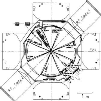
Figure 2 displays a median plan view of the cyclotron. The main systems involved in its construction are :
. The RF system : it covers the frev range using the harmonics 2, 3, 4 and 5 with 9.6 5 frf (MHz) 5 14.5. Such a RF frequency range leads to a rather compact resonator :extemal diameter a 1.2 m, lengti E 1.3 m, internal coaxial 563
line diameter ; 0.25 m and displacement of the short circuit z 0.7 m. The power dissipated at 100 kV turns out to be as low as 5 40 kW. IJsing two 40” dees and choosing to accelerate all the ions, whatever their output energy, with a constant turn pattern. the number of turns will be ; 250 and the turn sep‘aration at ejection =- 3 mm
I I I /
b Oil 012 oi3 oi4 Oi5 016 0:7
Figure 1. Energy range.
. The magnet : it will be built using 4 independent yokes and common circular poles (3.5 m in diameter) equiped with 4 straight 45” sectors. Each yoke includes 2*3 slices. the two main ones (6.4*2.4 m2) holding the poles have the maximum thickmess (0.85 m) we can obtained: they insure the rigidity. This scheme allows to minimise the weight (500 t) and the cost of the magnet and results in a good magnetic symmetry.
Hill and valley gaps are respectively 12 and 30 cm allowing an easy fitting of the 2 dees and giving a flutter well suited for focusing.
Using the TOSCA code, we have refined the magnet geometry so that the maximum correction required is as low as z f 200 gauss, the gradients being < 5 G/cm. A minimum of
11 circular trim-coils located on the vies, each one giving 7.5.10-2 G/AT (maximum gradient 2..5.10W3 G/cm/AT), will be used to shape the field within the required tolerances. The inner region (r < 20 cm) where the sectors join the central plug and the pole edge shaping are still to be refined.
. The central geometry : an axial injection and a Mueller type inflector are proposed with the goal to work out a fixed injection pattern suited for the harmonics 2, 3, 4 and a maximum ECR extraction voltage of 30 kV. To obtain lower energies (< 3 MeVlu) we have to use the harmonic h = 5, the injection voltage becomes very low and the acceptance (the intensities) will be reduced. This leads us to consider the use of 2 spiral inflectors, each one being optimised for given harmonics. In this case, a central geometry and a fixed orbit pattern will be associated to each inflector.
. The extraction system : it is quite conventional and includes one electrostatic deflector (divided into two parts) located in a valley f< 60 kV/cm) followed by two magnetic
channels (gradient compensation). Field bumps will be used to increase the turn separation up to 7 or 8 mm.
- The vacuum system : the lowest working pressure required to avoid the losses due 10 charge exchange turns out to be z 3.10m6 Pa. W e will use one T.M.P (2200 l/s) on each RF cavity and a large (z 24000 l/s) two stage (20 and 80%) cryopump inside the valley of injection. A caloduc. similar to the one used on AGOR, wiU be added and is under lest.
Figure 2. A median plane view of the cyclotron C. The beam chamcteristics
Using either the multiparticule code NAJO or the newly written one LIONS [3] we have simulated the beam behaviour in this cyclotron.
. Beam transmission : using similar central region and injection line (6D matching) as for our present GANIL injector [ 11, we can expect similar transmissions e.g 2 40% from the ion source analyzed beam to the cycloton extracted one (a 75% record transmission was obtained in our injector).
. Beam emittance : injecting a matched beam, 80~ mmmrad in each transverse plane and + 6” in phase width, leads in front of the extraction system to a monochromatic transverse emittance z 8.5x mm.mrad and to an energy dispersion of + 3.5%~. In these conditions, the extracted beam will contain parts of the 3 last accelerated turns and so the characteristics of the extracted beam will be lowered. However, it seems possible, at least for h = 2 - 3 to bunch the injected beam in a + 3 or 4” phase width, in this case due to the low energy spread a single turn extraction is possible and the extracted beam qualities are much improved (AWN = +l%c, transverse emittances g 8.5x mmmrad).
. Mass analysis : besides the usual analyser following the ECRIS which eliminates most of the contaminents, (see IV), the cyclotron will select Q/A within 3.5 to 1.5 10m4 depending upon the harmonic. These values should be sufficient for most of the experiments ; if not, we will use a thin target which will allow the selection of the right component within some 564
10e5 taking advantage of the difference in the energy losses of the various ions (isobars) through the foil. The resulting beam will of course suffer of the target crossing (mean energy, emittances and energy dispersion), nevertheless good characteristics could be restored, the price being to be paid on the intensity. This method will be limited to ions of A I80 at W > 6 McV/u.
IV. TIIE BEAM LINES
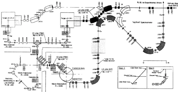
The layout of the SPIRAL beam lines is shown on the figure 3. We need to study and to build three beam lines.
cyclotron thus reducing the problems associated to the tuning of a composite beam and third to feed a possible low energy experimental area with a spare kind of ions.
. The high energy beam line (Bp 52.344 T.m) extends from the cyclotron exit to experimental caves through the second part of the or-spectrometer, a new analysing section being added. The acceptance of this line is 2&r mm.mrad and + 7%0 in energy dispersion. We will have to build = 24 m of new line divided into a first section allowing a betatronic isochronisation of the cyclotron beam and a second one to be used for the transversal matching of the beam at the target (if any) and then, to the object point of new analysing section.
Figure 3. Layout of the beam lines of SPIRAL.
. The primary beam line from the SSC2 output to the V. CONCLUSION target is the prolongation of L3. From the object point of the
(r spectrometer, the primary beam (Bp I 2.88 T.m) goes straight through the first a dipole and is bent down to the heavily shielded production target cave (-3.25 m) using an antisymetrical achromatic deviation and a two quadrupole doublet system devoted to the transverse matching of the beam on the target. The beam spot will be adjustable from + 2.5 to ? 20 mm for transverse emittances ranging from 2.5 to 67r mmmrad. This primary beam line z 14 m in len&th could be extended to a second target cave using the same optics.
. The low energy beam line from the ECRIS extraction to the cyclotron inflector (- 24 m) is divided in two main parts :
- The first part (Bp 5 0.136 T.m) includes an achromatic magnetic mass spectrometer system followed by a matching section to the second part. The optics [l] will insure a m/6m resolution z 250 for a 80~ mmmrad radial emittance. - The second part (Bp IO.050 T.m) similar to the oue used on our present injector is devoted to the 6D matching on the first accelerated orbit of a 80~ mm.mrad, + 6” in phase beam as accepted by the cyclotron.
- WC are also considering the possible use, between these two sections, of a new kind of large acceptance mass separator [4] giving a m/Fm resolution E 2000. Such an instrument should allow first to optimise and to have (using a spare ion) an on-line control of the radioactive ion production, second 10 reduce the number of ion species injected into the
The SPIRAL project has been accepted and funded in 1993. The planning foresees that the first tests of the cyclotron will start in mid 1997 using stable ions and that radioactive beams will be available by the end of 1998.
The project is estimated to 100 MF, not including the personal cost. Important collaborations are provided by other laboratories of the French Institutes (CEA and IN2P3).
This new facility will greatly enlarge the possibilities opened at GANlL in the field of radioactive ion beam physics at low and medium energy. Moreover, it will be built and operated without disturbing the classical use of GANIL
REWRENU3
111 - Ch. Ricaud et al, “Commissionning of the New High Intensities Axial Injection System for GANIL”, 131h. Int. Conf. on Cyclotrons and their Applications, Vancouver, Canada, July, 1992
[2] - P. Sortais et al, “An On Line Isotopic Separator Test Bench at GANIL”,Part. Act. Conf. Washington (1993). 131 - P. Bertrand “Programme LIONS (version l.O)“.Int.
report, GANIL R93.08.
141 - A. Chabert et al, “Principle of a new kind of large acceptance mass separator”, GANII, A94.01.