HAL Id: hal-02419688
https://hal.archives-ouvertes.fr/hal-02419688
Submitted on 19 Dec 2019
HAL is a multi-disciplinary open access archive for the deposit and dissemination of sci-entific research documents, whether they are pub-lished or not. The documents may come from teaching and research institutions in France or abroad, or from public or private research centers.
L’archive ouverte pluridisciplinaire HAL, est destinée au dépôt et à la diffusion de documents scientifiques de niveau recherche, publiés ou non, émanant des établissements d’enseignement et de recherche français ou étrangers, des laboratoires publics ou privés.
pin using a statistical approach
V. Blanc, V. Dupont, T. Beck, T. Lambert, E. Thebaud, F. Charollais, M.
Pelletier, A. Boulore, Jc. Dumas, B. Michel, et al.
To cite this version:
V. Blanc, V. Dupont, T. Beck, T. Lambert, E. Thebaud, et al.. Fuel melting margin assessment of fast reactor oxide fuel pin using a statistical approach. AIEA International Conference on Fast Reactors and Related Fuel Cycles Next Generation Nuclear Systems For Sustainable Development (FR17), Jun 2017, Yekaterinburg, Russia. �hal-02419688�
Fuel Melting Margin Assessment of Fast Reactor Oxide Fuel Pin Using a
Statistical Approach
V. Blanc1, V. Dupont1, T. Beck1, T. Lambert1, E. Thebaud1, F. Charollais1, M. Pelletier1, A. Bouloré1, JC. Dumas1, B. Michel1, M. Lainet1
1
CEA Cadarache, DEN, DEC, F-13108 Saint-Paul-lez-Durance, France
E-mail contact of main author: victor.blanc@cea.fr
Abstract. In the framework of the basic design of the Advanced Sodium Technological Reactor for Industrial Demonstration (ASTRID) project, the design margins have to be defined with accuracy. The design criterion considered here is the fuel melting margin during nominal operation condition, which is given by the melting probability. Oxide fuel temperature and melting temperature are calculated with CEA dedicated fuel codes, a computation scheme coupling GERMINALV2 for entire fuel pin with LICOS for a fuel pellet. Results could be dependent on parameters like manufacturing processes, irradiation conditions and fuel behavior laws. The aim of this paper is to take into account uncertainties associated to these parameters in the melting margin evaluation and to quantify its sensitivity in order to reduce uncertainties. First step is the description of uncertain parameters by appropriate distribution. Uncertainty propagation is then done by using meta-models, a multi-linear regression and an artificial neural network. As a result, the melting margin is depending of the linear heat rate first, stoichiometry and initial gap after. Defect as the fuel pellet off-centering within the clad, which need a 3D thermomechanical model, has as well a non-negligible effect. In a last section, melting probability obtained by Monte-Carlo simulations is compared to FORM-SORM approximations. This preliminary study shows that results are in a good agreement for SORM method, and that the melting probability depends considerably on radial offsets and initial hour-glass shape defects.
Key Words: Fuel, Sensitivity Analysis, Melting Margin, Failure Probability.
1. Introduction
The no-melting of the fuel is a first order criterion for the fuel element design of fast reactors. In fact, even though this phenomenon does not systematically induce a clad failure, axial movements of fissile nuclides could occur and cause major effects [1]. The first key variable to determine the melting margin is the fuel temperature which must also be calculated with accuracy and with its uncertainty. For this purpose, specific computation codes have been developed for fast reactor fuels simulation [2], [3], [4]. Thanks to advances in uncertainty propagation and reliability methods [5], and to the development of open-source statistics platform as URANIE [6], recent works have been done in order to compute the temperature field with uncertainties in PWR reactors fuel by coupling these codes with statistical methods [7]. The present study proposes to use these methods in order to improve the confidence of the maximum temperature evaluation and the melting probability of a SFR fuel. This study is based on the classical unidimensional model from CEA GERMINAL code [4] and on a tridimensional approach, using the dedicated model from CEA LICOS code [8] in order to take into account the range of fuel requirements.
First step of this study is the problem specification, which consists in input data modeling, code description, and variable and quantities of interest definition. Second step is the uncertainty propagation, which begins here with the building of a meta-model, and gives a sensitivity analysis. In the last section, an estimation of the melting probability with direct
Monte-Carlo simulations is compared to the standard approximation given by first and second order reliability methods (FORM/SORM).
2. Problem Specification: Input Data and Computation Tools
The design case studied consists of an inner core fuel pin from the CFV core of ASTRID, whose main characteristics are detailed in [9]. The present study is limited to the very beginning of the irradiation, knowing that the maximal fuel temperature is reached at the end of the first power rise.
2.1 Input Parameters
The calculation depends on a large number of input parameters such as geometry of the fuel elements, material thermal properties, filling gas composition in the free volume of the pin, irradiation power history, etc. The first step of a statistical approach allows achieving a specification of the problem, by listing all the input parameters which are considered having an effect on the fuel temperature. These parameters are considered as uncertain inputs and then, are modelized by parametric distributions (e.g. uniform or Gaussian), using either expert judgments or feedbacks from previous experimental SFR in France (Phénix, SuperPhénix).
2.1.1 Manufacturing process
The first category of input parameters is parameters depending of the manufacturing process (Table I) and of the tolerance requirements. They are highly dependent on the choice of the industrial process, and uncertainties can be reduced by limiting the manufacturing tolerances.
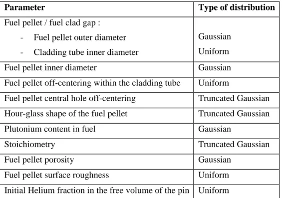
TABLE I: LIST OF CONSIDERED UNCERTAIN MANUFACTURING PROCESS PARAMETERS
Parameter Type of distribution
Fuel pellet / fuel clad gap :
- Fuel pellet outer diameter - Cladding tube inner diameter
Gaussian Uniform Fuel pellet inner diameter Gaussian Fuel pellet off-centering within the cladding tube Uniform
Fuel pellet central hole off-centering Truncated Gaussian Hour-glass shape of the fuel pellet Truncated Gaussian Plutonium content in fuel Gaussian
Stoichiometry Truncated Gaussian
Fuel pellet porosity Gaussian
Fuel pellet surface roughness Uniform Initial Helium fraction in the free volume of the pin Uniform
2.1.2 Irradiation conditions
The second category of input parameters is parameters depending on the irradiation conditions (Table II). Uncertain parameters coming from irradiation conditions are the widest ones, due to the difficulty of having direct measurement inside the core.
TABLE II: LIST OF CONSIDERED UNCERTAIN IRRADIATION CONDITION PARAMETERS
Parameter Type of distribution
Linear heat rate :
- Neutronic uncertainty
- Equivalent Plutonium linear mass1
Uniform Gaussian Duration of the first power rise Uniform Maximal clad temperature Uniform
2.2 Computation Codes
The CEA fuel simulation codes described below are hosted in a dedicated platform named PLEIADES.
2.2.1 GERMINAL V2
The CEA fuel simulation code dedicated to SFR, GERMINAL V2 [4], is used for this study. The code is able to calculate the thermal, physical and mechanical behavior of the fuel pin during nominal and transient operation condition, taking into account major phenomena which occur during the first power rise: fuel relocation, gap closure and evolution of the fuel-clad gap conductance (hgap). The fuel relocation model used gives a strain velocity which depends on the thermal gradient in the fuel pellet. This model is detailed in [10].
The thermal conductivity of the fuel and the gap closure velocity are first order parameters for the temperature field computation [7], but in the present paper, uncertainties in these models are not considered. Indeed, these law and model are validated with experimental results, and their influence on the temperature will be studied later. An exception is done: uncertainty on the solidus temperature of mixed Uranium-Plutonium oxide [11] is used to define the melting point in GERMINAL. The solidus temperature law depends on , and the burn-up. Uncertainty is included in the constant term, which represents the melting temperature for a non-irradiated UO2 fuel. A Gaussian distribution model with a standard deviation equal to 20 K is taken into account.
The problem being solved using classical 1,5D axisymmetric model, but this does not allow to take into account the geometrical defects which are not axisymmetric: fuel pellet-clad off-centering, central hole off-off-centering, hour-glass shape. A specific fuel code, the CEA LICOS code [8] from the PLEIADES platform is used in this aim.
1
2.2.2 LICOS
LICOS is a fuel performance code based on the finite element solver Cast3M [12]. Recent uses of LICOS have been presented in [8], especially the irradiation behavior calculation of a Phénix fuel pellet by a sequence of 1,5D GERMINAL scheme with a 3D finite element model. This computation scheme has been used in the present study. The difference with classical pellet fragment model is that, in this case, a 3D mesh dedicated to each defect is developed. Off-centering defects (central hole and pellet within the clad) being not axisymmetric, the models has to represent a quarter of the pellet (xOy and xOz stay symmetry planes). FIG. 1 shows the basis 3D finite element (FE) model for off-centering defects (a) and a top view of the central hole off-centering (b). For the initial hour glass shape defect, a pre-deformation is applied on the fragment of pellet. The pellet top surface, called the Inter-Pellet plane, is constraint by a kinematic condition of uniform displacement.
FIG. 1 : FE models dedicated to geometrical defects: (a) 3D finite basis element model, (b) central hole off-centering
2.3 Fuel Melting Margin Evaluation
At a given time step, the melting margin is defined by the minimum value between solidus temperature and maximum fuel temperature.
min , being the position.
This temperature margin is minimal at the level of maximal linear heat rate. LICOS computations are also performed with GERMINAL’s data extracted at this location. The sequencing between GERMINAL and LICOS computations being not automatic, a simple meta-model is elaborated in order to represent the temperature overheating caused by each defects (see section 3.1). The margin melting is then estimated with two steps: a GERMINAL calculation for the first evaluation of the temperatures and , and the 3D meta-model calculation for the maximal overheating induced by defects in the volume of the pellet:
3. Uncertainty Propagation
3.1 Pellet defects meta-model
The 3D calculations presented here are not able to represent every defect in a single mesh, and the sequence from GERMINAL to LICOS is not automatic. In consequence, we assume linearity of the overheating and an additive meta-model is elaborated, using a simple one-at-a-time design of experiment, in order to modeling the influence of each defect separately. This model takes the following form:
∆ '̅ ∆ ) '̅ * ∆ + '̅ * ∆ + '̅
∆ ) represents the overheating due to fuel pellet off-centering in the clad, ∆ + the overheating due to the central hole off-centering and ∆ + the overheating due to the initial hour-glass shape. The variable '̅ is the location in the 3D pellet. We observe that the maximal value of overheating is located in the median plane of the fuel pellet, on the surface of the central hole, but its location is depending on relative orientation between both off-centering defects. An angle , is also attached to each one, as presented FIG. 2. The maximal value of the overheating is obtained for a third angle, ,-./0%, which must be determined.
FIG. 2 : Definition of relatives positions of the fuel pellet off-centering and central hole defects
3.1.1 Pellet/clad off-centering
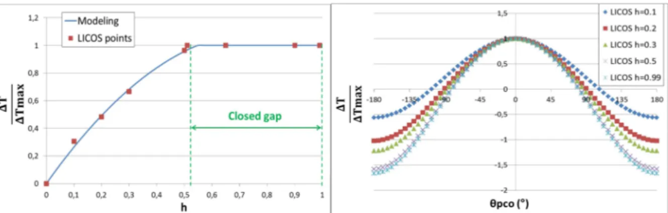
Pellet/clad off-centering amplitude can be defined as one parameter h which correspond to the ratio of pellet/clad radial off-centering over the initial pellet clad radial gap: 1 2345
6). Variations of maximal overheating with 1 and dependence of the overheating to the azimuth are shown on FIG. 3.
FIG. 3 : Maximal overheating due to fuel pellet off-centering at the end of the first power rise (a) and variation around vertical axis of the normalized overheating.
For a pellet off-centering lower than 50% of the initial gap, the maximal overheating increases with off-centering and can be modeled by a parabolic evolution. For off-centering values higher than 50% of the initial gap, overheating is constant, which can be explain by the fact that gap is closed at the end of the first power rise. Evolution of the overheating with azimuth for different values of off-centering is similar to a cosine function. The meta-model representing the overheating on the surface of the central hole with the pellet clad off-centering is described by the following equations:
7 89 1 : 0.5 ∶ ∆ ) ?1, ,) A BC. 1C* B . 1 . ?D 1 cos ,) * H 1 A 89 1 I 0.5 ∶ ∆ ) ?,) A 0.25 BC* 0.5 B . ?D 0.5 cos ,) * H 0.5 A
3.1.2 Central hole off-centering
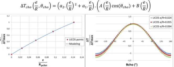
A similar method is used in order to model the thermal effect of an axial off-centering between the central hole and the pellet external diameter. FIG. 4 shows evolution of the maximal overheating with the off-centering normalized by the pellet ratio: evolution is parabolic. The evolution with the azimuth can be modeled by a cosine function. The meta-model takes the following form:
∆ + KM , ,L + N KBC. KMN ² * B .L MN . PD KL MN cos ,L + * H KMNQL
FIG. 4 : Maximal overheating due to central hole off-centering (a) and variation around vertical axis of the overheating. (b)
3.1.3 Initial hour-glass shape
An initial hour-glass shape can be induced by the pressing step during pellet manufacturing process. The maximal overheating caused by the hour-glass shape is localized on the inner circle of the pellet, in the plane of the minimal outer diameter, which corresponds to the larger pellet-clad gap. The diameter dependence of the overheating is clearly linear.
3.2 Global artificial neural network
With the use of the modeler module of URANIE, a global artificial neural network (ANN) [13] is developed, coupling both GERMINAL code and the geometric defects meta-model. Thereby, it is possible to determine the melting margin as described in section 2.3. The ANN includes one hidden layer with 15 neural units. The activation function implemented in URANIE for an ANN is a hyperbolic tangent. The construction of the ANN is divided into 2 parts: first, a learning phase is performed using about 80% of the available database; during this first step, best synapse weights are determined. Then a testing phase is performed with the 20% left to validate the ANN construction by verifying that the surrogate model is predictive.
In order to have a better description of the failure zone, the choice of an importance sampling as a design of experiment (DoE) is made with 10.000 sample points. With the URANIE launcher module, GERMINAL code and the geometric defects meta-model are launched on this DoE, the 10.000 simulations results being used as the database for the ANN construction.
3.3 Propagation with the surrogate model
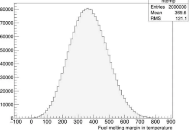
Once the surrogate model, i.e. the ANN, has been constructed, it is possible to launch a large number of Monte-Carlo simulations using this fast model. In order to do that, a new design of experiment is elaborate with a Latin Hypercube Sampling (LHS) of 2.000.000 sample points. This wide number of simulations allows us having a perfectly random sample without bias. With the use of URANIE, the probability density function of fuel melting margin in temperature is drawn FIG. 6. The distribution obtained is a Gaussian shape with a mean value of 370°C and a standard deviation of 121°C.
FIG. 6: Probability density function of fuel melting margin in temperature.
With the use of those 2.000.000 simulations, a sensitivity analysis can be performed to identify model inputs that cause significant uncertainty in the output. A reduction of the uncertainty of these latter should be performed afterwards if needed.
A variance-based global sensitivity analysis [14] is achieved using the Fourier Amplitude Sensitivity Testing (FAST) method. If we consider X as a vector of d uncertain model inputs
R , C, … , } and Y as a univariate model output, the decomposition of variance expression is given by:
UBV W = ∑ U WY + ∑ U[Z Z W + ⋯
The FAST method determines ` the first-order sensitivity index as ` = ab c a6d c.
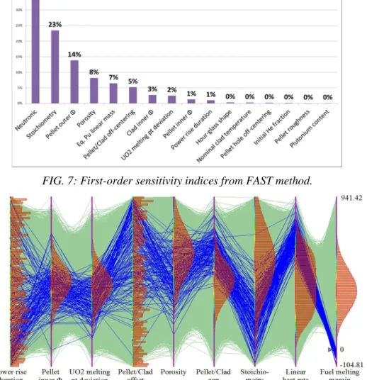
The first-order sensitivity indices from the previous data are plotted FIG. 7 and the sum of all those indices is 0.986 (close to 1). An observation of higher-order indices is not needed. The FIG. 7 shows that linear heat rate, stoichiometry and fuel clad gap are first order parameters. A Cobweb graph is drawn FIG. 8 representing the fuel melting margin versus the 8 most impactful uncertain inputs, each parameters being illustrated by its frequency distribution. Each one of the 2.000.000 simulations is symbolized by a green broken line linking every parameter, and the blue ones represent those whose fuel melting margins are negative, e.g. when the center of the fuel pellet is melting. Therefore it is quite easy to “follow a path” leading to a melting of the fuel pellet, and come to the conclusion that linear heat rate and stoichiometry have the biggest impact on the melting margin. This point confirms the conclusions obtained with the sensitivity analysis, and shows the direction each parameter is taking to lead up to a melting situation.
FIG. 7: First-order sensitivity indices from FAST method.
FIG. 8: Cobweb graph: Fuel melting margin VS 8 most impactful inputs.
4. Melting probability assessments comparison
Direct Monte-Carlo techniques can be used to estimate the melting probability, requiring a large sample to be consistent. The probability of failure e can be estimated by ffg where
The estimation accuracy can be evaluated in terms of its variance [15] with:
UBV?e A =?1 − e A ∗ eh
Then a confidence interval of 1-2α can be build [15] as: e ± lUBV?e A ∗ mn o where Φ is the probability density function of the standard normal distribution.
Direct Monte-Carlo simulations method is one of the most reliable method to determine a probability of failure, but it requires a very large panel of simulations for small probabilities. It is considered as the reference method here, named ed , but FORM and SORM have been also used in order to compare the results.
The First - and Second - Order Reliability Methods (FORM and SORM) are analytical and approximate methods which allow determining a failure probability. It consists of 4 steps [16]: transformation of the space of variables, research of the design point, approximation of the failure surface near the design point (by a tangent hyper plan for FORM and by a quadratic surface for SORM), and computation of the failure probability. These methods are applied to the studied case and compared FIG. 9 with Monte-Carlo method. Three different cases have been conducted: the first one is when all geometric defects and relative angles between offsets are taken into account; the second one is when all defects are considered but without any angles - meaning defects are considered aligned; and third one is when no pellet defect is considered.
FIG. 9: Comparison between Monte-Carlo and FORM/SORM.
The first conclusion that can be made is that FORM always overestimates the melting probability in comparison to Monte-Carlo (MC). In the other hand SORM and MC results are very close, even though SORM is slightly outside of the confidence interval. This means that the surface of failure at the design point cannot be approximated by a tangent hyper plan, but the quadratic surface approximation is more consistent. It should also be noted that timewise FORM and SORM require way less simulations than MC – between 500 and 1200 for FORM/SORM against several millions for MC. The MC method without geometric defect has not been performed, requiring too many simulations.
We also can see that taking into account geometric defects is necessary, leading to a melting probability over 1000 times more important. If the relative angles for geometric defects are not taken into account, the melting probability is multiplied by 3. However, an independence assumption of the defects has been made by considering them individually.
5. Conclusion
This paper proposes an example of uncertainty propagation method used in order to sort by importance uncertain input parameters, and to assess a failure probability of a fast reactor fuel element. With the uncertain distributions used, sensitivity analysis shows that linear heat rate, stoichiometry and radial gap must be well defined in order to reduce variance of the temperature at the beginning of life of the fuel. Defects as the fuel pellet off-centering within the clad, which need tri-dimensional calculations, have as well non-negligible impact.
Failure probability analysis shows that the first order reliability method overestimates the melting probability by a factor 6 compared to direct Monte-Carlo, whereas the second order gives a good approximation. Furthermore, the melting probability depends considerably on radial offsets and initial hour-glass shape defects, which have to be taken into consideration.
References
[1] GUERIN, Y., “Fuel Performance of Fast Spectrum Oxide Fuel”, Comprehensive Nuclear materials (2012), Elsevier, Vol. 2, p 547-578
[2] OZAWA, T. NAKAZAWA, H., ABE, T., “Development and verification of fast reactor fuel design code CEPTAR”, Nuclear Technology (2006), Vol.156, p. 39-55
[3] RITZHAUPT-KLEISSL, H.-J., HECK, M., “Development and verification of the SATURN-FS fuel rod computer code”, Nuc. Eng. and Design 101 (1987), p. 219-223 [4] LAINET, M., et al., “Recent modelling improvements in fuel performance code
GERMINAL for SFR oxide fuel pins”, Proc of FR13, Paris, 2013, IAEA-CN-199/241 [5] DE ROCQUIGNY, E., DEVICTOR, N., TARANTOLA, S., Uncertainty in Industrial
Practice, A guide to Quantitative Uncertainty Management. Wiley, 2008
[6] GAUDIER, F., “URANIE: the CEA/DEN uncertainty and sensitivity platform”, Procedia - Social and Behavioral Sciences, Vol. 2, issue 6, pp 7660-7661, 2010
[7] BOULORE, A., STRUZIK, C., GAUDIER, F., “Uncertainty and sensitivity analysis of the nuclear fuel thermal behavior “, Nuc. Eng. And Design 253 (2012), p. 200-210 [8] HELFER, T., et al., “Licos, a fuel performance code for innovative fuel elements or
experimental devices design”, Nuc. Eng. and Design 294 (2015), p. 117-136
[9] BECK T., et al., “Conceptual Design of Fuel and Radial Shielding Sub-Assemblies for ASTRID”, Proc. of FR17, Yekaterinburg, 2017, IAEA-CN-245-128
[10] LAINET M., et al., “Current status and progression of GERMINAL fuel performance code for SFR oxide fuel pins”, Proc. of FR17, Yekaterinburg, 2017, IAEA-CN-245-222 [11] MANARA D., et al., “The melting behavior of oxide nuclear fuels: effects of the
oxygen potential studied by laser heating”, Procedia Chemistry 7 (2012) 505-512 [12] http://www-cast3m.cea.fr/
[13] DREYFUS G., et al., “Neural networks-Methodology and applications”, Springer, 2005 [14] SALTELLI A., et al., “Global Sensitivity Analysis”, the Primer, J. Wiley & Sons, 2008. [15] RUBINSTEIN R.Y., “Simulations and Monte-Carlo Method”, Wiley Series in
Probability and Mathematical Statistics, J. Wiley & Sons, 1981
[16] DEVICTOR N., “Advances in methods for uncertainty and sensitivity analysis”, CSNI/WGRISK Workshop, Cologne, 2004