Publisher’s version / Version de l'éditeur:
ASHRAE Transactions, 77, 2, pp. 117-126, 1971
READ THESE TERMS AND CONDITIONS CAREFULLY BEFORE USING THIS WEBSITE. https://nrc-publications.canada.ca/eng/copyright
Vous avez des questions? Nous pouvons vous aider. Pour communiquer directement avec un auteur, consultez la première page de la revue dans laquelle son article a été publié afin de trouver ses coordonnées. Si vous n’arrivez pas à les repérer, communiquez avec nous à [email protected].
Questions? Contact the NRC Publications Archive team at
[email protected]. If you wish to email the authors directly, please see the first page of the publication for their contact information.
NRC Publications Archive
Archives des publications du CNRC
This publication could be one of several versions: author’s original, accepted manuscript or the publisher’s version. / La version de cette publication peut être l’une des suivantes : la version prépublication de l’auteur, la version acceptée du manuscrit ou la version de l’éditeur.
Access and use of this website and the material on it are subject to the Terms and Conditions set forth at
Calculation of heat conduction transfer functions for multi-layer slabs
Stephenson, D. G.; Mitalas, G. P.
https://publications-cnrc.canada.ca/fra/droits
L’accès à ce site Web et l’utilisation de son contenu sont assujettis aux conditions présentées dans le site LISEZ CES CONDITIONS ATTENTIVEMENT AVANT D’UTILISER CE SITE WEB.
NRC Publications Record / Notice d'Archives des publications de CNRC:
https://nrc-publications.canada.ca/eng/view/object/?id=1aca4130-1c7d-419f-a257-fb30f40e67eb
https://publications-cnrc.canada.ca/fra/voir/objet/?id=1aca4130-1c7d-419f-a257-fb30f40e67eb
T R A N S A C T I O N S
CALCULATION OF HEAT
CONDUCTION TRANSFER
FUNCTIONS FOR
MULTI-LAYER SLABS
D. G. STEPHENSON .I!cttrhc~r ..I SIIH..IED. (;. SrcSplrc.trsotr 1s Irrad. and (;. P. hlrrabs is rc.sc,arch oJ11c.c.r. Brrilditr~ Serr.icc>s Sec.riotr, />i~,isiotr of B~rilditrg Kcst-arclr. :~uriorra/ Rrscarch C'ororcil 01' Cutrado. O l l a w a . C'atwda. l71is papcSr was prepared Jbr presetrrariotr a / 11rt- A S I I H t I E Atrtrual htc.rritr~.
D. G. STEPHENSON
CALCULATION OF HEAT CONDUCTION
TRANSFER FUNCTIONS FOR
MULTI-LAYER SLABS
Prediction of the rate of heat flow, through walls and root's THE 2-TRANSFORM
made of several layers of different nlaterials and subject t o w h e n a function of tirne f ( t ) , is sampled at arbitrary variations of ambient conditions, is a problem ot' regular intervals of
A ,
the o u t p u t of the device is apractical importance in the design of buildings. One o f the . train of pulses, as shown in F*, 1 ( ~ 6 ) . l-he ~~~l~~ ~ f earliest and most extensive studies ot' the subject was n u d e transform of this o u t p u t signal is
by Ncssi and Nisollc' w h o developed a neth hod of calcula-
tion based o n the concept of "Fonctions d'lnfluence d e i(o) +
AN'^
+ f ( 2 ~ ) e - " ~ + . . .Flux." This solved the problem in principle; but the a m o u n t of computation involved was so great that it was of very little practical value a s long as the calculations had to be made by hand. Mackey and wright2 worked o n the same problem, but restricted themselves t o situations with periodic outside temperatures and constant conditions inside. Their work has been the basis f o r all air-conditioning design calculations made in America during the past 20 years.
T h c advent of digital computers has stimulated interest in t h e development of new design procedures t h a t arc b o t h more accurate and more suitable for machine computation. Mitalas a n d Stephenson3 have proposed a method that they call t h e thermal response factor m e t h o d . This is quite obviously a development of the Ncssi-Nisollc procedure. but is designed t o be used with a digital computer rather than by hand. Mitalas4 has uscd the responsc factor method t o solve problems with variable surface heat transfer coeffi- cients, and Kusuda5 has uscd the same technique to deter- mine the heat flux through cylindrical and spherical walls. T h e present paper presents a further development of the response factor approach. It applies the z-transform t o the problem of transient heat conduction. T h e resulting I.-trans- fer functions are similar t o t h e responsc factors, but they are much more economical in terms o f c o m p u t e r memory space and running time.
D. (;. S~c~plrctrsotr is /rc,ad. arrd (;. . t' hliralas is rc~sctarc/r o]]i'c,cr. Briildirrg Services Secriorr. I)i~~iviorr of Briilditrg Kcswarc~/r. :Valiotral
Rcssearch Coritrcil o]' Catrada. O!!awa. Catrada. 77ris paper as
prepared ]or prc~sc~trrariotr or r/rcB ASIIX,IE Atrtsial Alipc~ritrg. Washitrgrotr. D.C.. Augusr 22-25. I9 71.
I f I. is substituted for P A , the transform of t h e o u t p u t from
the sampler is
This polynomial in z-I is the z-transform of t h e function f ( t ) . T h e chief advantage of this t y p e of transform is that it can be obtained simply by sampling the function a t regular intervals: t h e successive o u t p u t s are the coefficients of successive powers of z- in the z-transform.
I f both the input and o u t p u t of a system are expressed in terms of their z-transforms. t h e ratio of the o u t p u t l i n p u t is a z-transfer function for the system. Assuming t h a t such a transfer function, K(z). can be found and that it can b e expressed a s the ratio of t w o polynomials in z-I , i.e.,
it follows that O(z), the z-transform of t h e o u t p u t that results f r o m an input represented by l(z) is
Both sides of this equation are polynomials, so that the coefficients of t h e various powers of z-I must b e the same o n the t w o sides o f the e q u a t i o n . Thus. equating t h e coeffi- cients of z-"' gives
0 A ? A A AA 5A 6 A 1A t -
Fk.
I Itrprtr and ortlprtl sigtuls of a ronyllrr. I,
.---
where the suhscript m , o n 0 and I. indicates the value of the function at t = mA. i.e.,
O m
is the coefficient of in the z-transform O(r). This expression relates the output at any time t = m A t o t h e input at that time and the values o f the input and o u t p u t at earlier times. T h e coefficients ao, . . . a~ a n d bo, . . . h r contain all the characteristics of the system. T h e .following Sections present methods for finding the coefficients of the r-transfer functions for heat flow and temperature at any plane in a multilayer wall. T h e starting point for the calculation is the s-transfer function.S T R A N S F E R FUNCTIONS F O R WALLS 4
'-
P u l r r r / f r o m S a m p l e r 4' / / ' I 1 I / /T h e term s-transfer function is used here t o indicate t h e ratio of the Laplace transforms o f o u t p u t / i n p u t . This is usually referred t o simply as a transfer I'unction. but t h e s has h e n added t o indicate that these are functions of the
lap la.^ parameter s. in the same way that /-transfer func- tions are functions of the parameter z.
T h e second edition of ('arslaw a n d Jaeger7 presents a succinct summary of Pipes' method8 for calculating heat flow through walls. It shows that the Laplace transforms of temperature a n d flux at inside and outside surfaces of a wall are related by a matrix expression of the form:
( 5 )
The square matrix o n the right of this equation is called the
/I--- /
rrurr.srnissiori rrrutrir.
I
I 1I
.
f o r the wall..-
-
T h e transmission matrix I'or a ~llultilayer wall is the
--
product of the transmission matrices for the various layers combined in the order in which they occur ill the wall. 'I'hus. I'or a wall of ?4 layers
1 1 1 ~ - thcrlnal rcslstancc 0 1 the layer.
'I hc dctcr~llinanl 01 the ~ransmission matrix for each layer is one. 'Thus. the determinant o f the transmission nlatrix for a nlultilayer wall, which is the product of the determinants for the component layers, is also unity, i.e.,
&.cause of this. Itq ( 5 ) can be re-arranged in the following forms. each suited t o a particular kind o f boundary condition:
('ase I : Temperature O 0 and O M given
Case 2 : Flux (bo a n d
aM
givenCase 3: TemperatureO0 and flux
aM
given('ase 4: Flux
a.
a n d temperatureO M
givenIt is also possible t o express the temperature and flux a t any plane inside a wall in t e r m s of a transfer function matrix and a column matrix of boundary conditions. Let O* and a * represent the Laplace transforms of temperature and flux. respectively, a t any internal plane. Consider that the wall consists of two parts: t h e part outside the plane of interest, with a transmission matrix
k:
ij.
a n d the part inside t h e plane of interest, with a transmission matrixF:
Dd.
T h e transmission matrix for the whole wall istherefore
T h e matrix equations relating o * a n d a * to the f o u r differ- ent column matriccs of boundary conditions are:
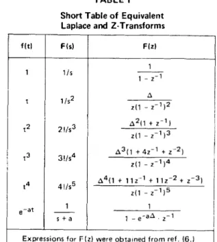
Case 2: TABLE I
Short Table of Equivalent Laplace and Z-Transforms Case 3 :
Case 4:
It is important t o note that all the s-transfer functions associated with one kind of boundary condition have the same denominator: B, when the surface temperatures are specified, C, for specified surface fluxes, and A o r D for the mixed kind of boundary condition. This simplifies the determination of the corresponding z-transfer functions because they also have a common denominator function associated with each kind o f boundary condition.
I I
Expressions for F ( z ) were obra~ned from ref. (6.)
Thus, powers of t higher than two will never yield stable z-transfer functions, and the t2 function produces a z-trans- fer function that has an oscillatory nature. This method is presented, therefore, for the case of a ramp input. (The results are equivalent to the response factors used by Mitalas4 and KusudaS.)
DETERMINATION O F A 2-TRANSFER FUNCTION
The z-transfer function associated with a particular s-trans- f e r function can be found in t w o ways:
M e t h o d I consists of choosing an input function that has a known Laplace transform and z-transform (this usually means either a step function o r a ramp function). The Laplace transform of the corresponding output is the Laplace transform of the input multiplied by the s-transfer function. This output is converted into a function of z and is divided by the z-transform of the input. The quotient is the z-transfer function that corresponds t o the s-transfer function.
M e t h o d 2 involves solving a set of simultaneous linear
algebraic equations t o obtain the coefficients of a z-transfer function whose frequency response matches the frequency response of the s-transfer function at certain selected fre- quencies.
T h e choice of method depends on the problem. When the boundary conditions can ~ I C expressed in terms of step
functions a n d ramp functions, the z-transfer functions should be based on these inputs. If, o n the other hand, the input is a continuous function that has a limited band width, it is best t o use the second method and match the frequency response a t several frequencies in the spectrum of the input function.
The following discussion is concerned with the transfer function A/B, but the same approach can be used for any of the transfer functions that occur in Eq ( 7 ) t o Eq ( 1 5 ).
For a ramp input the Laplace transform of the output is
A
s 2 g . This function can be expressed in the form of a sum as:
where s =
-fin
are the roots o f B = 0Method 1
Table I gives the Laplace transforms and z-transforms for a few simple functions o f time. The choice of the input func- tion is equivaient t o choosing a function for interpolating between the discrete values given by the z-transform coefficients. The use o f the step function is equivalent t o representing the input by a staircase approximation, whereas the ramp function is equivalent t o linear interpola- tion. It is important t o remember that the resulting z-trans- fer function will have poles at the zeros of the z-transform of the input, because the output has t o be divided by the z-transform o f the input. A z-transfer function is unstable if a n y of its poles lies outside the unit circle in the z plane.
and
Each of the terms in Eq ( 1 6 ) can be transformed into an equivalent z-transform by using the equivalent pairs of transforms in Table 1. Thus
When all these terms are added together t h e denominator of t h e s u m is
Hence,
so
t h a t D(z), t h e denominator o f O(z)/l(z), ism
[the constant A being taken into N(z)].
This denominator function has all its zeros inside t h e unit circle because all t h e values of
pn
are positive. T h e z-transfer function, therefore, will always be stable. Fur- thermore, D ( z ) depends only o n the r o o t s o f B and t h u s is t h e same f o r all transfer functions that have t h e same denominators in their s-transfer function counterparts.E q u a t i o n ( 2 1 ) s h o w s t h a t b o = I a n d b l =
w
- e-pnA. (The other coefficients o f D(z) are found
n = l
by multiplying t h e factors together.) There is a n infinite set of r o o t s of B = 0 lying along t h e negative real axis. Each value of
on
contributes -e-@nA t o b l a n d less t o all t h eAs O0 = 0 the coefficient o f z t l in N(z) is zero a n d the first term in N(z) is
o t h e r b coefficients, which are multiplied by factors always less t h a n o n e (i.e., o t h e r values of e-onA). T h u s all fin's greater t h a n some "cut-off" value have a negligible effect. T h e value of this "cut-off' point depends o n t h e precision required for t h e b values a n d o n t h e value of A. F o r ex- ample. if t h e values o f b l , b 2 , . . . are required t o be correct within
+
10- it is necessary thatT h u s for
a n d for
( T h e choice of t h e value for A is discussed in t h e section, Choice o f Sampling Interval.)
T h e values of t h e various "a" coefficients in t h e nu- m e r a t o r polynomial N(z) can be found by summing the numerators of the different components o f O(z) after they have been multiplied by t h e appropriate expressions t o g i v e t h e m all a c o m m o n denominator. It is more convenient, however, t o proceed in a slightly different way. T h e func- t i o n
can be evaluated f o r t = A, 2A, . . . t o give the coefficients 0 1 , 0 2 , . . . o f O(z). But by definition
so t h a t
Here again values o f
fin
greater t h a n some "cut-off" value have a negligble effect, and their effect gets progressively smaller for each successive value of a.This first method for finding K(z) can be summarized in the following steps:
( I ) Find t h e roots of the denominator of the s-transfer function.
( 2 ) Calculate D(z) using t h e roots found in S t e p I .
( 3 ) Evaluate the function of time that corresponds t o s - 2 times the s-transfer function, f o r t = A ,
2A, . . . , and thus obtain O(z). ( 4 ) Evaluate the coefficients of N(z) using
This procedure is illustrated in Appendix A.
Choice of Sampling Interval
T h e accuracy of the z-transfer function obtained by the method outlined above can be checked by comparing tts frequency response with that of t h e parent s-transfer func- tion. The frequency response of a n y s-transfer function can be obtained by evaluating the function at points lying along the imaginary axis in the s plane. The complex number (A/B),=iw represents the ratio of heat flux/driving ternpera- ture when the driving temperature is e i w t . 'm e frequency r e s p o n s e o f t h e c o r r e s p o n d i n g z-transfer function [N(z)]
/
[ D ( z ) ] can be obtained by letting z = e i w A . Fig. 2 shows the frequency response o f the z-transfer function corresponding t o A/B for a four-layer wall compared with "exact" values (i.e., those determined from the A / B func- tion directly). T h e z-transfer function wasobtained using a ramp function as the input. These results show that the frequency response of the z-transfer function matches the exact curve for small values of w, but as w approaches n/A t h e response of t h e z-transfer function deviates consider- ably from the exact curve. T h e agreement is quite good for frequencies less than about n / 6 A .It is important to note, however, that t h e z-transfer function obtained using a ramp function a s the input is "exact" for any input function composed of straight-line segments joining the ordinates that correspond t o its z-transform coefficients. Thus, the value o/' A should be
chosen so as t o make the polygon formed b y joining ordi- notes spuced ut intervuls of A u g o o d upproxirnution o/ !he input function. T h e output is exact for this type of polygon input even though the polygon input has t-'ourier series components with frequencies well above n/t)A. T h e samc applies for transfer functions based on step inputs if an input function can be wcll represented by a series o f step functions.
" " I
'I
Nl:)
Fig. 2 Frequency response of - for A = 1.0 and 0.25 hr using
Dlz)
linear in rerpolarion
Method 2
It is very desirable t o use a large value of A t o reduce the computation required when using the z-transfer functions. T h e upper limit is half the period of t h e highest frequency component present in the input function; but with the linear interpolation used in the first method it is necessary t o use a A that is only about 116 of this limiting value. T h e aim of this second method is t o obtain acceptable accuracy with larger values of A .
It is very inconvenient if all the z-transfer functions associated with o n e kind of boundary condition d o not have the same denominators. T h e denominators should be f o u n d , a s in the first m e t h o d , by using the poles of the corresponding s-transfer function. Hence, only the coeffi- cients of the numerators should be determined by using the exact frequency response d a t a . T h e aim is t o make
for selected values o f w . Thus.
But
@N(z)] ,=,iwA = a,-, + a l cos wA + a2 cos 2wA + a 3 cos 3wA + . . .
a , sin W A + a2 sin 2wA + a3 sin 3wA + . . .
\
(28) a n dwhere
V(W) = b l sin wA + b2 sin 2wA + b3 sin 3wA + . . . (31)
Therefore
where
Equating the real parts and t h e imaginary parts of E q
( 2 8 ) a n d Eq ( 3 3 ) gives a pair of equations relating t h e
unknown values of ao, a , , . . . t o the values of
X(w)
a n dY(w).
Thus, if N(z) is a polynomial of order J (i.e., J
+
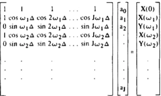
Ic o e f f i c i e n t s a o , . . . a , ) , the frequency response of N(z)/D(z) can be made t o m a t c h the exact frequency re- sponse at J / 2 frequencies in addition t o w = 0 . T h e result- ing J
+
I equations can be expressed in matrix f o r m , viz.: -1 1 1 . . . I
1 C O S W ~ A cos ~ w , A . . .
0 sin w l A sin 2wlA . . .
I cos w2A cos 2 w 2 A . . .
0 sln w2A sln 2w2A . . .
T h e u n k n o w n values of t h e a coefficients ca'n be found simply by premultiplying the column matrix o n the right side of E q ( 3 6 ) by the inverse of the square matrix o n the left.
T h e choice of the values o f w , , w 2 , e t c . should be based o n where it is most important to have t h e transfer function correct. For instance, if the transfer function is t o be used with climatic data a s the input, it is important t o have it accurate for w = n / 1 2 , n / 6 , 7714, n / 3 , n12.4, n / 2 . . . r a d / h r the frequencies of the fundamental and harmonics o f t h e basic daily cycle.
When w l A is small, t h e determinant of the square matrix is very small a n d the values of t h e coefficients ao, a l , . . . cannot be found with precision. O n the o t h e r hand, if w is large t h e frequency response o f the z-transfer func- tion can be poor for some frequencies between 0 and a , .
The maximum value of w A should not be too close t o n or the results also will be poor. Experience has indicated that for ordinary walls 1 0 coefficients are ample, and using A = I hr, w , = n / 6 , w 2 = n / 3 , w 3 = n / 2 a n d w 4 = n / 1 . 5 give quite good results. T h e improvement in t h e frequency response obtained by using this method ( r a t h e r than the first method with a ramp input function) is s h o w n in Fig. 3. There is o n e more slight modification that produces an improvement in the frequency response of t h e z-transfer function, viz,, using
The addition of the term z means that o n e f u t u r e value of the input is used in the calculation of the o u t p u t . This has
R C A L P A R T
Nlz)
Fig. 3 Frequency response of- with and without the coefficient
D l ~ l
the same beneficial effect in this case as it has in a numeri- cal integration formula.
There are some applications where a n expression involving a future value will greatly complicate the algo- rithm; but in the simple case of calculating heat flow through a wall that is exposed t o a specified ambient temperature, the future value of the input is always avail- able and can be used t o advantage.
EXAMPLE
Some of the advantages of the z-transfer function method can be seen in the following simple application. Consider the problem of calculating the rise in wall surface tempera- ture caused by the adsorption of energy from electric Lights (Fig. 4).
T h e s-transform of the surface temperature is
A .
whereT ls the s-transfer function for half the wall. The
A .
z-transfer function derived fromC is
Thus
But
where hm is the heat transfer coefficient between the sur- face and the environment. Therefore,
J 1
This expression can be used t o compute T, step by step. The value of the surface heat transfer coefficient can vary with time (if hm depends o n T m , iteration is neces- sary). There is a question, however, of which method t o use
P o w e r Absorbed b y W a l l S u r f a c e = W
A d i a b a t i c S u r f a c e Fig. 4 Curves o f heat
,'
.
I' f r o m S u r f a c e - L i g h t s" O N "
Time -,
flux at the surface o f a vs time.
for finding the coefficients of N(z). In this case N(z) is used with two different functions, viz: W , which is a step func- tion; and T , which can be approximated quite well by straight-line segments. Two different sets of X Q coefficients should, therefore, be used: one set derived with a step func- tion input t o be used with W and another set based o n a ramp function input with the surface temperature. Numeri- cal data are given in Appendix B.
CONCLUSION
The use o f z-transfer functions simplifies the calculation of transient heat flow through composite walls and roofs with- out requiring any assumptions except that the process can be described by linear differential equations. The same technique can be used to find the temperature and flux at any position in a wall.
The z-transfer functions can be derived t o cope with any variation of bc~indary parameters by choosing an appropriate time interval. T o reduce the length of the com- putation, however, a z-transfer function can be derived for a specific form of boundary parameter, i.e.. step, ramp or specified frequency spectrum.
In cases where the boundary parameter is known for at least one step ahead in time, a special z-transfer function taking account o f this forward value can be used t o improve the accuracy of the computations.
ACKNOWLEDGEMENTS
The authors gratefully acknowledge the programming assistance of Mr.
G.
Arseneault of the Division of Building Research, National Research Council of Canada, who pre- pared a program for the first method. The senior author also wishes t o express his thanks t o Mr. R. Gilles of Laboratoire Co. S.T.I.C. in France for his programming assistance and many helpful suggestions dunng the pre- paration of the paper.This paper is a contribution from the Division of Building Research, National Research Council of Canada, and is published with the approval of the Director of the Division.
REFERENCES
1. A. Nessi and L. Nisolle. RCgimcs variables dc fonctionnernent dans les installations de chauffage central. DUNOD. 1925;ard Rksolution pratique des probEmcs de discontinuih de fonction- nement dans k s installations de chauffage central. DUNOD.
193 3.
2. C. 0. Mackey and L. T. Wright, Periodic Heat Flow - Composite
Walls or Roofs. TRANSACTIONS. ASH&VE, Vol. 52, 1946. p. 283.
3. D. G. Stephenson and G. P. Mitalas. Cooling Load Calculations by Thermal Response Factor Method; and Room Thermal Response Factors, ASHRAE TRANSACTIONS. Vol. 73. Part 1, 1967. p. Ill. 2.1.-111. 2.10.
4. G. P. Mitalas, Calculation of Transient Heat Flow Through Walls and Roofs. ASHRAE TRANSACTIONS. Vol. 74. Part 11, 1968.
5. T. Kusuda, Thermal Response 1:actors for Multilayer Structures of Various Heat Conduction Systems. ASHRAE TRANSACTIONS. Vol. 75. Part 1. 1969.
6. E. 1. Jury, Theory and Application of the 2-Trandorm Method. 1964.
7. H. H. Carslaw and J. C. Jaeger, Conduction of Heat in SoMs. Second Ed., p. 326, Oxford University Press, 1959.
8. L. A. Pipes, Matrix Analysis of Heat Transfer Problems. Journal. Franklin Institute, Vol. 263. No. 3, March 1957, p. 195-206.
APPENDIX A After the roots of the functions A , B, C and D have been found, it is necessary t o evaluate the derivative o f each of the functions with respect t o s at each of the roots. If the derivative of a matrix is defined as the matrix whose elements are the derivatives o f thc analogous elements in
the original matrix, the derivative o f the product of several matrices follows the same rules as the derivative of the product of ordinary functions, viz.:
Supplementary Expressions
For a monolayer slab the function B can be expressed in
t h e form
- n2
a2
The roots of B = 0 are, therefore a t s =
-
SO7
M
when [ H I =
n
[ H j ]j= 1
The closed form expression for B can be differentiated t o give Thus A and since L- 1 { S 2 B \
-
= o a t t = o Hence n2n2t OD --The transfer functions that occur where the boundary conditions are of the second kind have the function C as the denominator. This function always has a root a t s = 0 as
well as an infinite number of roots along the negative real A
axis. Thus the function
~ Z C
has a third order pole at s = 0and must be expressed as The roots of the elements of the transmission matrix
for a multilayer slab depend o n the dimensions and thermal properties of all t h e layers and cannot be expressed in any simple way. They can be found, however, numerically: it is only necessary t o evaluate t h e functions A, B, C o r D for a sequence of negative real values of s. When t h e value of o n e o f t h e functions changes sign between one value of s and the next, i t indicates that a root is located in that interval, a n d it can be located precisely by an iterative procedure. It is necessary, therefore, t o search the range from s = 0 t o the "cut-off" using small increments of s s o a s n o t t o miss any pairs o f roots.
When s =
-$I,
where$
is a positive real numberwhere
The values of p l and pz can be found without having Similarly, the surface temperature response t o a step func- t o evaluate the derivatives of sA/C: as the surface tempera- tion input of flux is also zero at t = 0
ture response to a ramp input of flux is zero at t = 0
hence
APPENDIX B
Numerid D.tr For Exwnpk Wall
n
Roots of B = 0
in units of hr - 1
l+dfbiarts of DIx)
Coefficients of Numeraton N(z) by 1st Method
DIB
I
11BI
AIBThese coefficients were obtained by matching the frequency response at n16, n13, n12 and n11.5 radianslhr, and at w = o the value of real part and the derivative of imaginary part.
Codficiants of Numereton N(z) by 2nd Method
NOMENCLATURE I(z) = z transform of excitation function.
A,B,C,D = the elements of the heat transmission matrix for a wall. J = order of the polynomial N(z).
(A subscript o or i o n these elements indicates that the K(z) =-,The N(z) z transfer function that corresponds t o a matrix is for the part of a wall outside or inside a D(z) Laplace Transfer Function.
DIB
particular plane of interest in the wall.) th
L = thickness of j layer.
E:j=
[HIM
J = number of layers in a multilayer wall JP N(z) = aQ;Q, The numerator of the z-transfer function K(z)
D(z) = bpzdQ, The denominator of the z-transfer function K(z). Q=O
1 lB
I
AIBu
E(z) =
Op
, The z-transfer function that corresponds t o A/C.[HI = [Hi] The heat transmission matrix for a wall of
M
layers.j= 1
The heat transmission matrix for the jth layer in a wall.
O(z) = K(z) I(z) , The z transform of the output that results from excitation I(z).
P = order of the polynomial D(z).
Q = rate of heat conduction away from the surface of a wall. Lj
R. =
-,
thermal resistance of jth layer.J k~
M
R = Rj, thermal resistance of a wall. j=I
T = temperature of a wall surface iw A
U(w)
-
iV(w) = D(z) for z = eW = rate of absorption of radiation from hghts by a wall. iwA X(w)
-
iY(w) = N(z) for z = e -Q ap = coefficient of z in N(z). -Q bQ = coefficient of z in D(z).A
co. c', = residues oi- a t the doublc. pole a t a = O
s2 B A
d = residue of- at s = -J .
s2B
e = base of natural logarithms. f(t) = value of function at time t.
h = combined convections and long wave radiation heat transfer coefficient at a surface.
i
=J--i-
j = layer number for a multilayer wall starting from the outside. th
k. = thermal conductivity of j layer.
J
Q = an index to identify terms in a series. m = an index to indicate time.
n = an index to identify terms in a series.
A Po- P,
.
p2 = residues of-
at s = 0 S ~ C A q = residue of- at s = - y n , s2cs = Laplace transform parameter. t = time.
-Q
xQ = coefficient of z in numerator of E(z).
-Q
yp = coefficient of z in denominator of E(z).
. .th
nj = thermal dil'iusivity 01 1 l a c r .
-b = roots ol' B = 0, i.e. t) =
fi
(s + ,j ). n n = l7 = roots of C = 0, i.t. C =
n = I
A = sampling interval for sampled data system.
00, O M = Laplace transform of temperature at outside and inside surface of a multilayer wall, respectively.
O * = Laplace transform of the temperature at the plane of interest inside a wall.
O* = Laplace transform of the heat flux through the plane of in- terest inside a wall.
n = 3.1416.. .
~ . 2
T . =
I,
characteristic time for jth layerJ aj
OO, O M = Laplace transform of heat flus through the outside and inside surfaces of a multilayer wall respectively.
0 = is a positive real number.
w = angular velocity.
DISCUSSION
R O B E R T A. WALKER, (Veterans Administration, Wash- ington, D.C.): I a m thinking of t h e practical application of this information. I gather t h a t the heat transfer is, as y o u p o i n t e d o u t , a function o f t h e surface temperature.
N o w o n t h e wall say t h a t is exposed t o solar radiation, t h e surface temperature depends o n t w o things, the solar radiation a n d I believe o n t h e conduction of the wall itself. S o it seems t o me that somewhere then you're left with a n insoluble problem, aren't y o u ?
Y o u are getting t h e conduction based o n surface temperature a n d y e t y o u can't find t h a t until y o u know the conduction. Would y o u explain that?
MR. MITALAS: O n e can set u p a surface heat balance that relates surface t e m p e r a t u r e a n d surface heat flux. This gives a pair of e q u a t i o n s o r a s m a n y equations a s needed t o solve f o r a set of u n k n o w n factors. F o r example, o n e of them could be h e a t conduction, a n o t h e r could be convection, a
third - radiation. A detailed discussion of this problem is given in a paper, "Calculation of Transient Heat Flow Through Walls a n d Roofs," published in ASHRAE TRANS- ACTIONS, Vol. 74, Part 11, 1968.
Z. 0 . CUMALI, (Consultants Computation Bureau, San Francisco, Calif.): What is the computational efficiency of this compared t o the standard series response f a c t o r form, which is t h e V transfer form?
MR. MITALAS: This is very difficult t o answer. One in- dication of the efficiency is t h e reduction of arithmetic operations, in s o m e cases b y approximately five, a s well a s reduction of storage locations.
MR. CUMALI: And then division?
R e p r i n t e d f r o m ASHRAB T R A N S A C T I O N S 1 9 7 1 , P a r t I I , V o l u m e 7 7 b y p e r m i s s i o n
o f t h e A m e r i c a n S o c i e t y of H e a t i n g , R e f r i g e r a t i n g a n d A i r - C o n d i t i o n i n g B n g i n e e r s , I n c . C o p y r i g h t 1 9 7 4 . Q A S E R A I T R A N S A C T I O N S .