HAL Id: hal-01320381
https://hal.archives-ouvertes.fr/hal-01320381
Submitted on 1 Mar 2021HAL is a multi-disciplinary open access archive for the deposit and dissemination of sci-entific research documents, whether they are pub-lished or not. The documents may come from teaching and research institutions in France or abroad, or from public or private research centers.
L’archive ouverte pluridisciplinaire HAL, est destinée au dépôt et à la diffusion de documents scientifiques de niveau recherche, publiés ou non, émanant des établissements d’enseignement et de recherche français ou étrangers, des laboratoires publics ou privés.
Pr4Ni3O10+δ: A new promising oxygen electrode
material for solid oxide fuel cells
Vaibhav Vibhu, Aline Rougier, Clément Nicollet, Aurélien Flura, Sébastien
Fourcade, Nicolas Penin, Jean-Claude Grenier, Jean-Marc. Bassat
To cite this version:
Vaibhav Vibhu, Aline Rougier, Clément Nicollet, Aurélien Flura, Sébastien Fourcade, et al.. Pr4Ni3O10+δ: A new promising oxygen electrode material for solid oxide fuel cells. Journal of Power Sources, Elsevier, 2016, 317, pp.184-193. �10.1016/j.jpowsour.2016.03.012�. �hal-01320381�
1
Pr
4Ni
3O
10+δ: a new promising oxygen electrode material
for Solid Oxide Fuel Cells
Vaibhav Vibhua, Aline Rougiera, Clément Nicolleta, Aurélien Fluraa, Sébastien
Fourcadea, Nicolas Penina, Jean-Claude Greniera and Jean-Marc Bassata*
a CNRS, Université de Bordeaux, Institut de Chimie de la Matière Condensée de Bordeaux (ICMCB), 87 Av. Dr Schweitzer, F-33608 Pessac Cedex, France.
Abstract
The present work is focused on the study of Pr4Ni3O10+δ as a new cathode material for Solid
Oxide Fuel Cells (SOFCs). The structural study leads to an indexation in orthorhombic
structure with Fmmm space group, this structure being thermally stable throughout the
temperature range up to 1000 °C under air and oxygen. The variation of oxygen content (10+δ)
as a function of temperature under different atmospheres show that Pr4Ni3O10+δ is always
oxygen over-stoichiometric, which further suggests its MIEC properties. The polarization
resistance (Rp) of Pr4Ni3O10+δ electrode is measured for GDC/co-sintered and two-step sintered
half cells. The Rp for co-sintered sample is found to be 0.16 Ω∙cm² at 600 °C under air, which
is as low as the one of highest performing Pr2NiO4+δ nickelate (Rp = 0.15 Ω∙cm² at 600 °C).
Moreover, an anode supported (Ni-YSZ//YSZ) single cell including GDC//Pr4Ni3O10+δ
co-sintered electrode shows a maximum power density of 1.60 W·cm-2 at 800 °C and 0.68 W·cm
-2 at 700 °C. Here, the work is emphasized on the very close electrochemical performance of
Pr4Ni3O10+δ compared to the one of Pr2NiO4+δ with higher chemical stability, which gives great
interests to consider this material as a very interesting oxygen-electrode for SOFCs.
Keywords: SOFC, Nickelates, Chemical stability, Oxygen over-stoichiometry, OER
Corresponding author at: CNRS, Université de Bordeaux, Institut de Chimie de la Matière Condensée de Bordeaux (ICMCB), 87 Av. Dr Schweitzer, F-33608 Pessac Cedex, France.
2
Tél.: +33 (0)5 40 00 27 53; Fax: +33 (0)5 40 00 27 61. E-mail address: [email protected]
1. Introduction
The decrease of the operating temperature of the SOFCs is a critical challenge for their
commercialization. Currently, the main objective is to decrease it down to around 600 – 700°C,
in an effort to decrease the device cost (for example, using stainless steel instead of ceramics
as interconnects) and to improve the cell durability. However, since the electrode reactions as
well as ion transport through the electrolyte are temperature-driven, the electrochemical
performance drastically decreases with temperature. Hence, it is mandatory to improve the
materials and architecture of the cell in order to reach reasonable performances at intermediate
temperatures (600−700 °C). It is well known that promising materials for cathodes are Mixed
Ionic and Electronic Conducting (MIEC) oxides [1-7].Several attempts were made to find the
best MIEC material for SOFCs in last few decades.
Recently Ruddlesden-Popper (RP) phases Lnn+1NinO3n+1 (Ln = La, Pr or Nd) have shown
excellent transport and electrochemical properties [6, 8-9]. The crystal structure of these phases
can be described by the stacking of a finite number (n = 1, 2, 3 mainly) of perovskite-type
LnNiO3 layers and one rock salt LnO layer along the crystallographic c-direction
((LnO).(LnNiO3)n) [10-11]. The first member of the RP family of nickelates, n = 1, is
Ln2NiO4+δ, which adopts the K2NiF4 –type structure with one layer of corner-sharing NiO6
octahedra along the c-direction.
In the second member of RP nickelates, n = 2 (Ln3Ni2O7±δ), two infinite NiO6 sheets are
connected in c-direction between the rock salt layers. For n = 2, the electrical conductivity is
significantly enhanced compared to Ln2NiO4+δ as the nickel oxidation state and electronic
3
Similarly, the structure of Ln4Ni3O10+δ (n = 3) is built with three infinite NiO6 sheets
connected in c-direction between the rock salt layers. Greenblatt reported that the smallest rare
earth ion able to still stabilize Ln4Ni3O10+δ is Nd [11]. A metallic conductivity is observed for
all the Ln4Ni3O10+δ phases and a metal-to-metal transition is observed for the Ln = Pr and Nd
at 145 and 165K, respectively [11, 12]. The Pr4Ni3O10+δ has higher conductivity value in the
25−300 K temperature range than Nd4Ni3O10+δ, but lower than La4Ni3O10+δ. Regarding
Pr4Ni3O10+δ, Bassat et al. have previously shown that the material is metallic [12], the transport
properties being highly dependent on the δ-value. Depending on the synthesis technique the δ
varies from −0.1 to +0.1.
The first member of RP family, Ln2NiO4+δ (Ln = La, Pr and Nd) compounds have already
evidenced promising results when used as cathode materials for SOFCs due to their MIEC
properties [13-15]. Pr2NiO4+δ has the best electrochemical properties among three nickelates,
especially at intermediate temperature (600−700°C) [16]. We have recently reported the
decomposition of Pr2NiO4+δ into PrNiO3-δ, Pr4Ni3O10+δ and Pr6O11 at the operating temperature
range (600 to 800 °C) during long term [17]. A very interesting point is that even after complete
dissociation the electrochemical performance, at least under idc = 0 condition, do not show
significant change (i.e. the same polarization resistance (Rp) values are obtained before and
after ageing). Therefore, it is our goal to study the behaviour of these new forming materials,
and in this study we especially focused on Pr4Ni3O10+δ.
According to author’s knowledge, the literature on Pr4Ni3O10+δ remains scarce and limited to
non-stoichiometry, transport and magnetic properties [10, 12], whereas its use as oxygen
electrode in the field of SOFCs has never been reported. An effort was then made to investigate
the properties of Pr4Ni3O10+δ, mainly the non-stoichiometry, chemical stability under different
4
2. Experimental
2.1. Powder preparation
The Pr4Ni3O10+δ phase was synthesised using the Glycine Nitrate Process (GNP) [18]. The
corresponding precursors were Pr(NO3)3.6H2O (Sigma Aldrich , 99.99%), Ni(NO3)2.6H2O
(Acros Organics, 99%) and glycine (Sigma Aldrich , 99.9%). The final annealing was
performed at 1000 °C for 48 h under oxygen leading to well crystallized phases. Intermediate
grinding and annealing steps were performed 3 times.
2.2. X-ray diffraction analysis
The powders were first investigated by X-Ray diffraction (XRD) at room temperature using
a PANanalytical X’pert MPD diffractometer with Cu-Kα incident radiation to check the purity
of phase. The XRD vs T (i.e. in situ XRD) were performed to check the stability of phase with
temperature under air. The data were recorded for both heating and cooling, from room
temperature up to 1000°C, by steps of 100°C. The heating and cooling rate was fixed to 2
°C.min-1, the powder being thermally equilibrated for 2 h at each particular temperature prior
to the XRD data recording. The X-ray diffractogram recorded on the powder during cooling is
preferentially reported here thanks to a thermal equilibrium which is expected to be more easily
reached in this case.
The ageing test of powder was performed under air. Green pellets were first prepared and
then left into a furnace for 1 month at 600, 700 and 800 °C, before the XRD characterization.
Each X-ray diffractogram was fitted by profile matching using the Fullprof software.
5
The microstructures of Pr4Ni3O10+δ powder and the electrodes morphology were observed by
field emission Scanning Electron Microscopy (JEOL JSM 6330 A) equipped with an EDS
detector.
2.4. Thermo Gravimetric analysis (TGA)
TGA experiments were carried out using a TA Instrument TGA-Q50 device, with the aim i)
to determine the delta value, δ, at room temperature under air, ii) to investigate the thermal
stability vs. pO2 and iii) to study the δ variation vs. T under air and oxygen atmospheres. In the
first case the powders were beforehand heated under air up to 1000 °C, then cooled down to
room temperature with a slow rate (2 °C.min-1), this cycle being reproduced twice to ensure a
stable state of the material, i.e. a reproducible oxygen content. Then, a second cycle was
performed under Ar - 5% H2 flux with a very slow heating rate of (0.5 °C.min-1), the
decomposition of the material leading to the determination of the oxygen stoichiometry after
cycling the sample down to room temperature (Pr2O3 and metallic Ni being formed as checked
by XRD after the thermal cycle). Secondly, the thermal stability of Pr4Ni3O10+δ was
investigated as a function of pO2, the variation of the oxygen stoichiometry of the materials
being successively studied under air (pO2 = 0.21 atm) and oxygen (pO2 = 1 atm), using heating
and cooling rates of 2 °C.min-1. For this purpose, the powders were first thermodynamically
equilibrated under air in the TGA device as described above (i.e. two cycles were performed
under air). The gas was changed at room temperature and again two cycles were performed
under oxygen. During cycling, the powder was left for 1 h at 1000 °C and room temperature.
6
It was first expected to prepare dense pellets by sintering the green pellets at 1000 °C for 24
h under oxygen, which are mandatory conditions to ensure keeping the pure Pr4Ni3O10+δ phase.
However, it is worth mentioning that we could not succeed probably because of such limitation
of temperature, 70 % being the highest density value obtained. The electrical conductivity was
then determined under air using the four-probe technique, in the temperature range 20 − 800
°C with the heating and cooling rate of 1 °C.min-1.
2.6. Preparation of symmetrical half cells
For the electrochemical studies, symmetrical half cells
(electrode//GDC//8YSZ//GDC//electrode) were prepared. Dense pellets of 8YSZ (8 mol.%
yttria stabilized zirconia) with diameter ≈ 18 mm and thickness ≈ 1.2 mm (preliminarily
sintered at T = 1400 °C) were used. The symmetrical half-cells were prepared by screen
printing using two ways, i.e. two-step or co-sintering of the GDC/electrode layers.
Terpineol-based slurries were prepared from as prepared Pr4Ni3O10+δ powder and commercial GDC
powder (Rhodia-Solvay). In order to increase the electrochemical performances of the
half-cells [16], a 2-3 µm GDC bi-layer was initially screen printed on both sides of the 8YSZ
electrolyte pellet. The main role of GDC is, a) to obtain good interface and b) to stop the
reactivity, between electrode and electrolyte.
Regarding the two steps sintering way, the GDC layer was first sintered at 1375 °C for 1 h
under air. The electrode layer was then screen printed on each side of the GDC//8YSZ//GDC.
The sintering study of the electrodes will be detailed in the Results and Discussion part.
The symmetrical half cells were also prepared by co-sintering the GDC and electrode layers.
7
After drying (T 80 °C), the electrode layer was deposited on both sides by screen printing technique and co-sintered with GDC layer at 950 °C for 2 h under air.
A single cell was fabricated starting from a commercial anode supported half cell (Elcogen
ASC-10C type) made of a 500 µm thick Ni-8YSZ anode and a 3 µm thick 8YSZ electrolyte
membrane (Ø = 50 mm). A GDC layer (Ø = 25 mm) was first deposited on Ni-8YSZ//8YSZ
support and then dried at 80 °C. After the deposition and sintering of the cathode layer (Ø = 16
mm, see Single Cell measurements part), a LaNi0.6Fe0.4O3-δ (LNF) layer (Ø = 16 mm) was
deposited to improve the current collection [19].
2.7. Electrochemical measurements
The electrochemical properties of the symmetrical half-cells were characterized by
Electrochemical Impedance Spectroscopy (EIS). The initial EIS measurements were carried
out under air, in the temperature range 500 – 800 °C under zero dc conditions. Gold grids (1.024
cm-2 meshes) were used as current collectors. The impedance diagrams were recorded at steady
state under potentiostatic control with 50 mV ac amplitude, from 106 Hz down to 10-1 Hz,
using a frequency response analyser module Autolab FRA2, coupled with a
potentiostat/galvanostat PGSTAT 302N. The polarization resistance (Rp) values were obtained
by taking the difference between the low frequency (LF) and the high frequency (HF) intercepts
with the real Z'-axis of the Nyquist representation. The complex impedance diagrams were
fitted using an equivalent circuit by means of the Zview® (Scribner Associates) to measure the
Rp of different processes.
Prior to single cell measurements, the anode was reduced using the following procedure: after
heating in N2 up to 800 °C, the anode side was flushed with hydrogen gas with a flow rate of
8
of 500 ml.min−1. The impedance diagrams were recorded at OCV, 0.9, 0.8 and 0.7 V, at the
operating temperatures, namely 800 and 700 °C. The ageing of a single cell at 700 °C was
performed at a current density of 0.3 A·cm−2, using a Frequency Response Analyzer module
Autolab FRA2, coupled with a potentiostat/galvanostat PGSTAT 302N.
3. Results and discussion
3.1. XRD analysis
The XRD characterization of as-prepared Pr4Ni3O10+δ phase shows that the material
crystallizes in an orthorhombic structure with Fmmm space group. The full pattern profile
matching refinement leads to determine the following lattice parameters: a = 5.3714(2) Å, b =
5.4611(2) Å and c = 27.5271(3) Å (Fig. 1a), these values are in good agreement with the
previously reported results [10, 12].
3.1.1. Thermal behaviour of the material with temperature under air (XRD vs. T)
The thermal variation of the X-ray diffractogram under air shows that the Pr4Ni3O10+δ phase
remains stable up to 1000 °C; with increasing temperature, the structure keeps always the
orthorhombic symmetry and is indexed with the Fmmm space group. An example is given in
Fig. 1a; at 1000 °C the refinement of the data leads to the following lattice parameters: a =
5.4300(4) Å, b = 5.4858(3) Å and c = 27.8910(3) Å. The absence of additional peaks with
regard to the room temperature diagram confirms the stability of the material up to 1000 °C
under air.
9
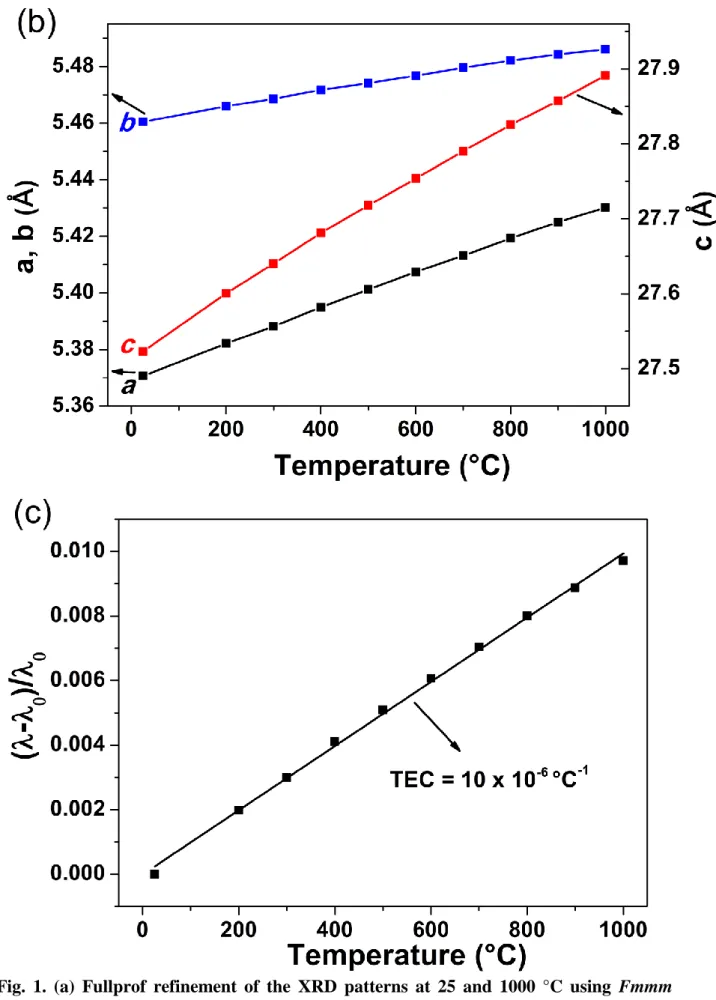
In Fig. 1b, the variations of a, b and c lattice parameters as a function of temperature are
plotted. All of them show linear increase throughout the temperature range. The thermal
expansion coefficient of Pr4Ni3O10+δ was calculated from the thermal variation of the lattice
parameters i.e. the slope of (λ-λ0/λ0) vs T (Fig. 1c), where λ and λ0 are cubic root of volume at
particular temperature and room temperature respectively. The value of TEC is close to ~10 ×
10-6 °C-1 which is in the same order of those of the other components of SOFCs [20]. Following
dilatometry measurements, a TEC value of 12 × 10-6 °C-1 was also determined; the observed
discrepancy could be assigned to the fact that the pellet was not sufficiently dense.
3.2. TG analyses
Because the electrochemical behaviour of the material will be studied under air, we aim first
to determine the over-stoichiometry value δ after thermal equilibration under air, following the
synthesis which is performed under oxygen. Later on, the evolution of δ vs. T under air and
oxygen will be recorded. Another part of this TGA study will aim to determine the thermal
stability range of the material either under air or oxygen.
3.2.1. Determination of 𝛿 of material equilibrated under air
The δ-value for Pr4Ni3O10+δ was calculated using TGA experiments performed under
reducing conditions (5% H2/Ar atmosphere, Fig. 2a). Two major weight losses occur: the first
one at around 400 °C, which corresponds to the reduction of Ni3+ into Ni2+ (corresponding
plateau Pr4Ni3O9 is formed [21]), while the second weight loss corresponds to the complete
reduction of Ni2+ into metallic Ni0. Finally the total reduction of Pr
4Ni3O10+δ into Pr2O3 and Ni (within the appropriate ratio) is then evidenced, leading to the determination of δ. The
10
calculated value corresponding to the first plateau and after total reduction results in the almost
same value, δ = 0.10 0.01 at room temperature.
3.2.2. Behavior under air and oxygen
TGA experiments were carried out under air and oxygen with the aim to investigate the
chemical stability and to find the most appropriate temperature and atmosphere for the sintering
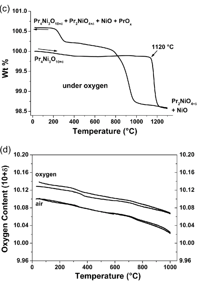
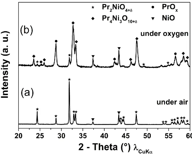
of electrodes made of this material (refer to experimental part). Fig. 2b and 2c show the
variation of the weight loss with temperature for Pr4Ni3O10+δ in air and in oxygen atmosphere,
respectively; the results largely depend upon pO2. Under air, Pr4Ni3O10+δ exhibits thermal
stability up to ~1050 °C. Above this temperature it starts decomposing and around T = 1140
°C, it is completely decomposed into Pr2NiO4+δ and NiO (Fig. 2b). This decomposition was
checked by XRD, both on the powder at the end of this TGA cycle (cf. Fig. S1a) or after
quenching another set of powder from 1200 °C to RT in a separate furnace (not reported). This
decomposition is completely irreversible under air, Pr2NiO4+δ phase being stable under air as
confirmed by a second TGA cycle (not reported).
Under oxygen, Pr4Ni3O10+δ shows higher stability than in air, up to 1120°C (Fig. 2c) and
above this temperature, it decomposes again into Pr2NiO4+δ and NiO (as checked by XRD
again). However, the behaviour when cooling under oxygen is completely different than what
was previously observed under air. Indeed, Pr2NiO4+δ starts again changing into Pr4Ni3O10+δ
and PrOx (around 950 °C). The XRD analysis at the end of cooling process shows the presence
of mixture of Pr4Ni3O10+δ, Pr2NiO4+δ, PrOx and NiO (cf. Fig. S1b), which is in agreement with
the previously reported results for PrNiO3-δ [22].
11
In the following, the thermal variation of the oxygen content was investigated over the
stability domain of Pr4Ni3O10+δ, i.e. from room temperature up to 1000 °C (cf. Fig. 2b, c).
Before starting the experiment, the powder was first equilibrated under air, ensuring the starting
value of δ ~ 0.10. For both atmospheres, two cycles were performed to reach the reversibility
while the powder was kept for 1 hour at the 1000 °C before cooling. The thermal variation of
the oxygen content, 10+δ, under air and oxygen is plotted in Fig. 2d. In air, a reversible
behaviour is observed during both cycles.
Under oxygen, the material is up taking oxygen during first cycling, then, a reversible
behavior is observed (2nd cycle is reported). One should point out that thematerial is always
oxygen over-stoichiometric within the whole stability temperature range.
The cycling was also performed under argon up to 800 °C (cf. Fig. S2 and S3), and as
expected a small decrease in oxygen content is observed during first cycle while during second
cycle a reversible behavior is observed. The calculated δ values at room temperature after
thermal equilibration under the considered atmospheres are 0.14 (Ni3+ ~ 76%), 0.10 (Ni3+ ~
73%) and 0.07 (Ni3+ ~ 71%) under oxygen, air and argon, respectively. Furthermore it can be
concluded that the material is “breathing” oxygen quite easily i.e. it is easy to include more
interstitial oxygen under oxygen after equilibration under air, and it is also quite easy to remove
the same amount of oxygen under argon (~ 0.03 in both cases).
As an intermediate conclusion, the above TGA study indicates that the thermal stability limit
is 1120 °C and 1050 °C under oxygen and air, respectively, but we are aware that these
observations are governed by kinetics. Moreover we checked that the long term thermal
stability of the material is ensured at 1000 °C under oxygen, indeed this is the synthesis
condition of Pr4Ni3O10+δ. It was also investigated that the material is stable under air at 950 °C.
12
3.2.4. Long term chemical stability at operating temperatures
Following previous studies performed till high temperature, it’s also mandatory to check the
thermal stability of the material at the operating temperatures of SOFCs. Then the ageing of
Pr4Ni3O10+δ powder was performed under air during one month at 600, 700 and 800 °C.
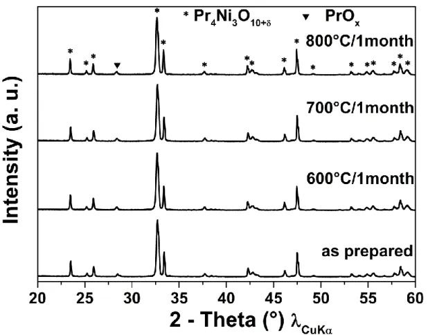
The corresponding XRD diffractograms along with as prepared powder are shown in Fig. 3.
The material is chemically very stable at these SOFCs operating conditions, indeed, only a very
small peak of PrOx is observed (however existing in the as-prepared powder as well). This long
term stability indicates that this material is suitable to be used as oxygen electrode, which will
be checked in the final part regarding electrochemical measurements.
3.3. Electrical Conductivity
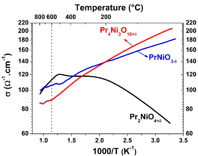
The variation of the total electrical conductivity σ vs. 1000/T for Pr4Ni3O10+δ is reported in
Fig. 4, and compared with the corresponding data for PrNiO3-δ and Pr2NiO4+δ. Pr4Ni3O10+δ
shows metal-like behaviour over the temperature range up 20−800 °C under air, as PrNiO3-δ
but unlike Pr2NiO4+δ which shows semiconducting behaviour. The maximum conductivity
value observed for Pr4Ni3O10+δ is close to 200 S.cm-1 (at room temperature) which is the
highest value among Pr4Ni3O10+δ, PrNiO3-δ and Pr2NiO4+δ phases and is in agreement with the
one earlier reported result [12]. The conductivity varies from ~85−200 S.cm-1 from 800 °C to
room temperature. At a typical operating temperature of 600 °C, Pr4Ni3O10+δ shows electrical
conductivity, σ = 90 S.cm-1, similar to those of other Pr-based nickelates for ex. PrNiO
3-δ (σ ~ 106 S.cm-1) and Pr
2NiO4+δ (σ ~ 112 S.cm-1) (Fig. 4), meeting the requirement for a SOFC cathode material.
13
In general, in a material showing metallic behavior the decrease in conductivity observed
with increasing temperature can be understood in terms of decrease of the charge carrier
mobility while the charge carrier amount remains almost constant. Here, because the material
is exchanging oxygen with the surrounding atmosphere upon heating (cf. Fig. 2d), one can
wonder if the corresponding decrease of the holes amount (Ni3+) is large or not. As the Ni3+
percentage is not showing significant change with increasing temperature (73 to 70 % from
room temperature to 800 °C), it can be concluded that the decrease in the conductivity is due
to a decrease of the charge carrier mobility as expected.
Considering the expected MIEC properties of the Pr4Ni3O10+δ phase, as in all atmospheres,
the material remains always oxygen over-stoichiometric (see TGA part), the behavior should
be MIEC whatever the pO2 throughout the temperature range of stability, however it would be
to confirm experimentally measuring the ionic (oxygen) conductivity.
3.4. Electrochemical studies
In the second part of the work, we aimed first at the preparation of electrode ink using
Pr4Ni3O10+δ powder prior to its shaping by screen-printing on 8YSZ//GDC supports. The
sintering was performed using two different ways. The EIS vs. T measurements were performed
and the results discussed comparing both sets of data obtained with the two kinds of half cells.
Finally, single cells measurements (i-V curves recording at the operating temperatures 800 and
700°C) were performed using the sintering way optimized in the previous step (at idc=0).
3.4.1. Morphology of as-prepared powder
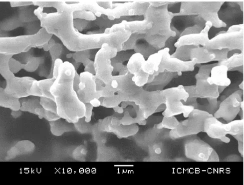
Before the preparation of ink, the morphology of the as prepared powder was investigated by
14
flame temperature which characterized the auto-combustion GNP process may explain this
result. Therefore this powder was attrited with zirconia balls in ethanol medium for 1 h with
the aim to obtain very fine powder, indeed a mean particle size of about 0.6 μm (as checked
using laser granulometry measurements) was finally obtained.
3.4.2. EIS characterization: symmetrical cell
EIS measurements were carried out on Pr4Ni3O10+δ//GDC//8YSZ symmetrical half cells.
These ones were prepared using two routes, either by a two-step process or co-sintering GDC
and the electrode (detailed in experimental part). Then it will be possible to compare the
polarization resistances, Rp, and the shape of impedance curves obtained in both cases.
3.4.3. Optimization of the two-step sintering process
The two-step sintering condition was first optimized using several sintering temperatures
under oxygen. The sintering was first performed at the temperature corresponding to the phase
stability limit, i.e. 1000 °C as discussed above. However one hour sintering is not sufficient
from the mechanical point of view (confirmed by "tape test"); therefore 2 h of sintering is
minimal. When the sintering was performed during 2 h at 1000°C, the Rp value is very high (Rp
= 2.7 Ω∙cm² at 600 °C, cf. Fig. S5). Hence for better electrochemical performances it is
mandatory to sinter the electrode at higher temperature.
The sintering at T > 1050 °C/1h leads to partial decomposition into Pr2NiO4+δ and NiO,
however, a slow cooling under O2 leads to the re-formation of Pr4Ni3O10+δ (cf. Fig. 2c) [22].
The lowest the cooling rate is, the lowest the amount of Pr2NiO4+δ is expected. Then for
preparing the electrodes, the half cells were cooled at 1°C/min from the sintering temperature
15
recovery of Pr4Ni3O10+δ phase. The corresponding X-ray diffractogram of the half cell sintered
at 1150°C shows Pr4Ni3O10+δ as major phase and no peak for Pr2NiO4+δ is observed (cf. Fig.
S6).
Progressive increase of sintering temperature up to 1050 and 1150 °C leads to further
decrease in the Rp values down to 1.05 and 0.25 Ω∙cm² respectively at 600 °C. Further increase
of the sintering temperature leads to small increase of Rp, up to 0.40 Ω∙cm² when the sintering
temperature is 1200 °C. Hence the sintering at 1150 °C for 1 h is obtained as an optimized
condition, however it leads to the appearance of some additional phases (PrOx and NiO) (cf.
Fig. S6). To avoid such additional phases, it’s important to perform the sintering up to 1000 °C
(thermal stability domain of Pr4Ni3O10+δ). For this purpose, co-sintering of GDC and electrode
was applied.
3.4.4 Co-sintering of GDC and Pr4Ni3O10+δ half cell
Aiming at favoring pure Pr4Ni3O10+δ phase, the symmetrical half cells were prepared by
co-sintering GDC with the electrode at 950 °C for 2 h. The co-sintering condition was already
optimized in our group. Air was chosen instead of oxygen for sake of simplicity. In-situ (in the
electrochemical cell) and ex-situ (in the furnace) co-sintering experiments lead to similar Rp
values of 0.16 Ω∙cm² at 600 °C. Moreover after the co-sintering thermal cycle, no change is observed in the X-ray diffractogram of the electrode with respect to the starting Pr4Ni3O10+δ
powder (cf. Fig. S7).
16
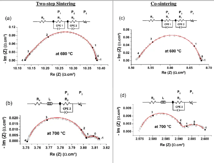
The EIS data were recorded between 500 and 800 °C. In Fig. 5 (a, b) and Fig. 5 (c, d) the
Nyquist impedance diagrams are compared at 600 °C and 700 °C for two-step sintered and
co-sintered half-cells, respectively. In both cases, three processes for T < 700 °C (P1, P2 and P3)
instead of two (P2 and P3) for T ≥ 700 °C are distinguished. At higher temperature, T ≥ 700 °C,
as all processes are shifted toward higher frequencies, the process P1 is hidden by the
inductance of the wires and hence could not be distinguished anymore. The processes P1
(appearing at high frequency (104 – 103 Hz)) and P
2 (appearing at middle frequencies (103 – 1 Hz)) were fitted using two parallel R//CPE elements for the sake of simplicity, at 600 °C. The
origin of process P1 is likely due to O2- solid state diffusion in the interphase formed at the
interface of GDC//electrode layer, as reported for Pr2NiO4+δ [23]. Indeed, at the electrode//GDC
interface Pr-cations partly diffuse into the GDC layer forming Pr-doped ceria interphase, and
the O2- diffusion should occur on this new phase formed thanks to its MIEC properties [24,
25]. The process P2 is assigned to the oxygen electrode reaction (OER) at the Pr4Ni3O10+δ
electrode (R//C shape), it is due to the relaxation of oxygen exchange reaction at the interface
gas//electrode similar as Pr2NiO4+δ [23]. The process P3 is due to gas diffusion impedance as
already reported [26, 27], and usually fitted using one Warburg element Ws. The fit of the
impedance data was carried out in order to extract only the Rp values. The total Rp, calculated
for all temperatures (500−800 °C range) for the two-step sintered and co-sintered half cells
under air, are plotted in Fig. 6a.
The Rp values obtained by co-sintering are slightly lower than those corresponding to the
two-step sintering way, for ex. at 600 °C, the Rp for co-sintered and two-step sintered half cells
are 0.16 and 0.25 Ω∙cm², respectively. However, these Rp values remain close to that of
Pr2NiO4+δ (Rp = 0.15 Ω∙cm² at 600 °C), which is currently the lowest value exhibited by
17
In order to identify the origin of the difference in Rp values, the thermal variations of Rp
related to the three processes namely P1, P2 and P3, are plotted in Fig. 6b. Interestingly, the Rp
values of the P1 and P3 processes for co-sintered and two-step sintered half cells are almost the
same, however the differences are only observed for P2 process, depending on the sintering
way. For the co-sintered half-cell, the Rp values are lower than that for the two-step sintered
half cells. So it can be concluded that in both ways of sintering, the main difference is coming
from the OER due to Pr4Ni3O10+δ electrode (process P2). The slightly higher value of Rp for P2
of two-step sintered half cells can either be related to the presence of additional phases (PrOx
and NiO (cf. Fig. S6)) or to the electrode microstructure. In general, at high sintering
temperature, the particles coarsening should result in the decrease in active surface area that
could affect the OER.
The frequency of relaxation of different processes involved in both fabrication processes are
compared in Fig. 6c. Only the P1 process shows some differences, which is likely related to
the morphology of the interface (cf. Fig. 7). Indeed, for the two-step sintered half cell, the GDC
layer (sintered separately at 1375 °C for 1h) is much denser than the one of the co-sintered half
cell, which leads to a higher relaxation frequency. It is worth noting that the frequencies of
processes P2 (OER on Pr4Ni3O10+δ electrode) and P3, (gas diffusion process), are logically
almost identical for both processes.
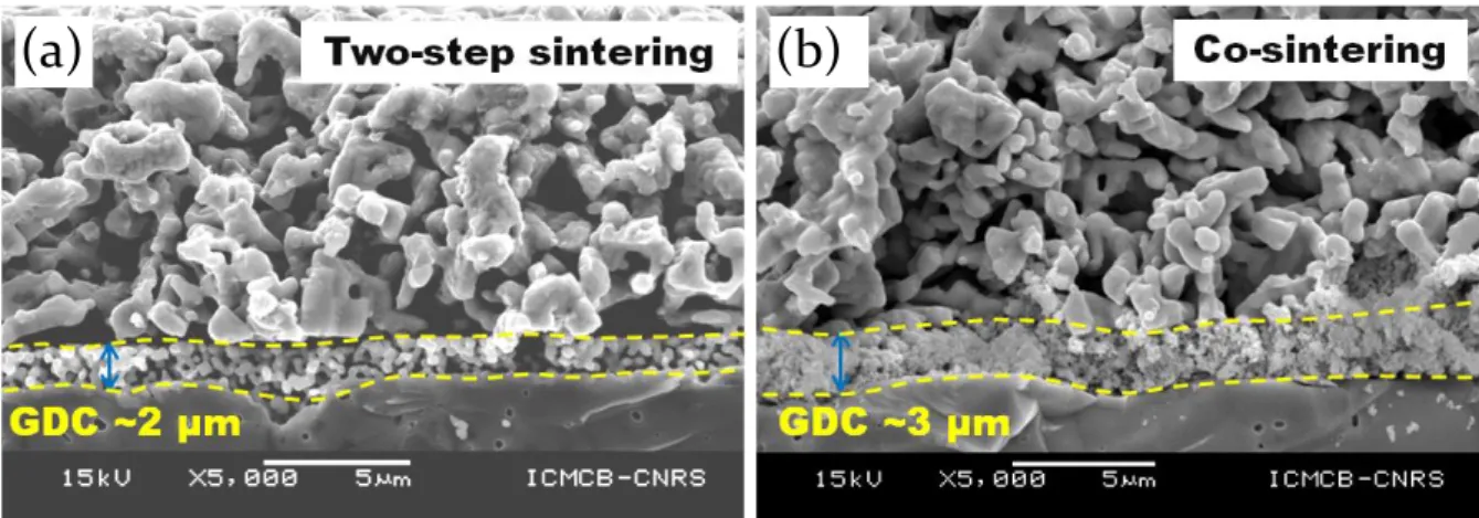
3.4.6. Morphology of half cells after EIS measurements
SEM observations of the Pr4Ni3O10+δ electrode were carried out after EIS measurements (Fig.
7). The thicknesses of the electrodes are estimated to be ~10 µm. It can be noticed that all the
layers are well adhered with each other. From the SEM micrographs it seems that the GDC
18
and 3 µm respectively for two-step sintered and co-sintered half cells. A careful observation of
the microstructure also suggests the morphology of the electrode is denser in case of two-step
sintering. This can be linked to particles coarsening at high sintering temperature.
3.4.7. Single cell measurements
The cathode sintering was performed using the previous optimized conditions determined for
half cells, which is co-sintering together with the GDC layer at 950 °C for 2 h under air. The
single cell was mounted into the measurement setup, with flows of air and N2 on the cathode
and anode sides, respectively. The cell was heated at 800 °C and N2 at the anode side was
progressively replaced by dry hydrogen (H2) to reduce NiO into metallic Ni. The open circuit
voltage (OCV) was around 1.1 V as expected. The i-V characteristic was measured from OCV
down to 0.4 V, and the impedance diagrams were recorded at OCV, 0.9, 0.8, and 0.7 V (not
reported). Then the temperature was decreased at 700 °C to measure again the i-V characteristic
and impedance diagrams.
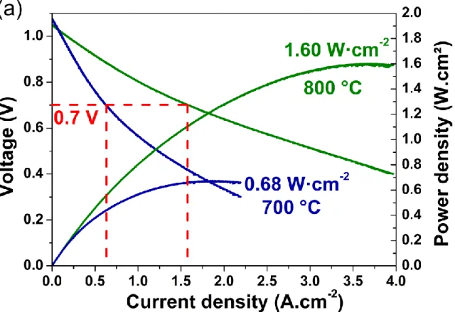
Fig. 8a shows the cell voltage as a function of the current density, as well as the resulting
power density at 800 °C and 700 °C. The cell performance is high, reaching maximum power
densities of 1.6 W·cm-2 at 800 °C and 0.68 W·cm-2 at 700 °C. For a potential of 0.7 V, the
current density is 1.6 A·cm-2 at 800 °C and reaches 0.64 A·cm-2 at 700 °C.
Following the measurements at 800 and 700 °C, the cell was aged at 700 °C for 500 h at a
current density of 0.3 A·cm-2. Fig. 8b shows the cell voltage as a function of time; the potential
started at around 0.80 V, then a slight decrease is observed and after 500 h the potential is
around 0.76 V.
19
This work reports the structural, stability and electrochemical studies of Pr4Ni3O10+δ as a new
promising cathode material for SOFCs. Pr4Ni3O10+δ was successfully synthesized via
glycine-nitrate route under normal oxygen flow (pO2 ~ 1 atm). It crystallizes in orthorhombic structure
with Fmmm space group. The XRD vs. temperature experiment under air shows a stable phase
throughout the temperature range up to 1000 °C.
An over-stoichiometry, delta value δ = 0.10 is obtained under air. The measurement of oxygen
content vs. T shows that the material is always over-stoichiometric whatever the pO2 is, which
should indicate that this material is MIEC-type under oxygen and air up to 1000 °C.
Pr4Ni3O10+δ phase is stable maximum for 2 h under air and fully stable under oxygen at 1000
°C. Further increase of temperature leads to decomposition into Pr2NiO4+δ and NiO, under air
and oxygen.
The half cell prepared by co-sintering process shows lower Rp value (Rp = 0.16 Ω∙cm² at
600°C) than the one made by two-step sintering (Rp = 0.25 Ω∙cm² at the same temperature),
which is almost same as Pr2NiO4+δ. A single cell with Pr4Ni3O10+δ electrode produced high
power density of 1.60 W·cm-2 at 800 °C and 0.68 W·cm-2 at 700 °C.
Endly, the Pr4Ni3O10+δ phase is highly stable during long term up to 1 month under air at
different SOFC operating temperatures: 600, 700 and 800 °C, contrarily to Pr2NiO4+δ which
forms PrNiO3-δ, Pr4Ni3O10+δ and Pr6O11 in the same conditions [17]. It can be then concluded
that the electrochemical behavior of Pr4Ni3O10+δ is similar to that of Pr2NiO4+δ, but with a quite
higher stability, which gives great interests to consider this material as a very promising oxygen
electrode.
20
S1: X-ray diffractograms after TGA performed on Pr4Ni3O10+δ powder under (a) air and (b)
oxygen. S2: Thermal variation of weight loss for Pr4Ni3O10+δ under argon atmosphere. S3:
Thermal variation of the oxygen content (10+) under argon (30 °C ≤ T ≤ 800 °C). S4: Morphology of as-prepared powder after synthesis by GNP. S5: Rp measured at 600 °C under
air on the half cells prepared by two-step sintering process at 1000°C/2h/O2, 1050°C/2h/O2 (+
950 °C/6h/O2), 1150°C/1h/O2 (+ 950 °C/6h/O2) and 1200°C/1h/O2 (+ 950 °C/6h/O2) and
slowly cooled. S6: X-ray diffractogram of half cells after sintering at 1150 °C for 1 h under O2
(+ 950 °C/6h/O2). S7: X-ray diffractograms after EIS measurements performed by co-sintering
technique (comparison with powder).
Acknowledgements
The authors wish to gratefully acknowledge the Agence Nationale de la Recherche (A.N.R.,
France) for financial support. The authors also acknowledge Eric Lebraud for XRD,
Dominique Denux for thermal measurements.
References
[1] A. Aguadero, L. Fawcett, S. Taub, R. Woolley, K.-T. Wu, N. Xu, J. A. Kilner, S. J. Skinner, Materials development for intermediate-temperature solid oxide
21
[2] S. Peng, Y. Wei, J. Xue, Y. Chen, H. Wang, Pr1.8La0.2Ni0.74Cu0.21Ga0.05O4+δ as a potential cathode material with Co2 resistance for intermediate temperature solid oxide
fuel cell. International Journal of Hydrogen Energy, 38, (2013) 10552-10558.
[3] H. Zhao, Q. Li, L. Sun, Ln2MO4 cathode materials for solid oxide fuel cells. Science China Chemistry, 54 (2011) 898-910.
[4] A. J. Jacobson, Materials for solid oxide fuel cells. Chemistry of Materials, 22 (2010) 660-674.
[5] C. Sun, R. Hui, J. Roller, Cathode materials for solid oxide fuel cells: A Review. Journal of Solid State Electrochemistry, 14 (2010) 1125-1144.
[6] A. Tarançon, M. Burriel, J. Santiso, S. J. Skinner, J. A. Kilner, Advances in layered oxide cathodes for intermediate temperature solid oxide fuel cells. Journal of Materials
Chemistry, 20 (2010) 3799-3813.
[7] D. J. L. Brett, A. Atkinson, N. P. Brandon, S. J. Skinner, Intermediate temperature solid oxide fuel cells. Chemical Society Reviews, 37 (2008) 1568-1578.
[8] G. Amow, S. J. Skinner, Recent developments in Ruddlesden–Popper nickelate systems for solid oxide fuel cell cathodes. Journal of Solid State Electrochemistry, 10 (2006)
538-546.
[9] S. Choi, S. Yoo, J.-Y. Shin, G. Kim, High Performance SOFC Cathode Prepared by Infiltration of Lan+1NinO3n + 1 (n= 1, 2, and 3) in Porous YSZ. Journal of the
Electrochemical Society, 158 (2011) B995-B999.
[10] Z. Zhang, M. Greenblatt, Synthesis, Structure, and Properties of Ln4Ni3O10-δ (Ln = La, Pr and Nd). Journal of Solid State Chemistry, 117 (1995) 236-246.
[11] M. Greenblatt, Ruddlesden-Popper Lnn+1NinO3n+1 nickelates: Structure and properties. Current Opinion in Solid State and Materials Science, 2 (1997) 174-183.
22
[12] J.-M. Bassat, C. Allançon, P. Odier, J. P. Loup, M. Deus Carvalho, A. Wattiaux, Electronic properties of Pr4Ni3O10±δ. European Journal of Solid State and Inorganic
Chemistry, 35 (1998) 173-188.
[13] A. Aguadero, J. A. Alonso, M. J. Martinez-Lope, M. T. Fernandez-Diaz, M. J. Escudero, L. Daza, In situ high temperature neutron powder diffraction study of
oxygen-rich La2NiO4+δ in air: correlation with the electrical behaviour. Journal of
Materials Chemistry, 16 (2006) 3402-3408.
[14] E. Boehm, J.-M. Bassat, P. Dordor, F. Mauvy, J.-C. Grenier, P. Stevens, Oxygen diffusion and transport properties in non-stoichiometric Ln2-xNiO4+δ oxides Solid State
Ionics, 176 (2005) 2717-2725.
[15] C. N. Munnings, S. J. Skinner, G. Amow, P. S. Whitfield, I. J. Davidson, Oxygen transport in the La2Ni1-xCoxO4+δ system. Solid State Ionics, 176 (2005) 1895-1901.
[16] C. Ferchaud, J.-C. Grenier, Y. Zhang-Steenwinkel, M. M. A. van Tuel, F. P. F. van Berkel, J.-M. Bassat, High performance praseodymium nickelate oxide cathode for
low temperature solid oxide fuel cell. Journal of Power Sources, 196 (2011) 1872-1879.
[17] V. Vibhu, J.-M. Bassat, A. Flura, C. Nicollet, J.-C. Grenier, A. Rougier, Influence of La/Pr ratio on the ageing properties of La2-xPrxNiO4+δ as cathodes in IT-SOFCs. ECS
Transaction, 68 (2015) 825-835.
[18] L. A. Chick, L. R. Pederson, G. D. Maupin, J. L. Bates, L. E. homas, G. J. Exarhos, Glycine-nitrate combustion synthesis of oxide ceramic powders Materials Letters, 10
(1990) 6-12.
[19] M. C. Tucker, L. Cheng, L. C. Dejonghe, Selection of cathode contact materials for solid oxide fuel cells. Journal of Power Sources, 196 (2011) 8313-8322.
[20] A. Flura, S. Dru, C. Nicollet, V. Vibhu, S. Fourcade, E. Lebraud, A. Rougier, J.-M. Bassat, J.-C. Grenier, Chemical and structural changes in Ln2NiO4+δ (Ln=La, Pr or Nd)
23
lanthanide nickelates as a function of oxygen partial pressure at high temperature.
Journal of Solid State Chemistry, 228 (2015) 189-198.
[21] P. Lacorre, Passage from T-type to T'-type arrangement by reducing R4Ni3O10 to R4Ni3O8 (R = La, Pr, Nd). Journal of Solid State Chemistry, 97 (1992) 495-500.
[22] V. Vibhu, J.-M. Bassat, A. Flura, C. Nicollet, N. Penin, J.-C. Grenier, A. Rougier, Structural and stability studies of PrNiO3-δ and characterization as air electrode in
SOFCs. Submitted in Journal of Material Chemistry A, 2015.
[23] A. Flura, C. Nicollet, S. Fourcade, V. Vibhu, A. Rougier, J.-M. Bassat, J.-C. Grenier, Identification and modelling of the oxygen gas diffusion impedance in SOFC porous
electrodes: Application to Pr2NiO4+δ. Electrochimica Acta, 174 (2015) 1030-1040.
[24] P. Shuk, M. Greenblatt, Hydrothermal synthesis and properties of mixed conductors based on Ce1-xPrxO2-δ solid solutions. Solid State Ionics, 116 (1999) 217-223.
[25] R. Chockalingam, A. K. Ganguli, S. Basu, Praseodymium and gadolinium doped ceria as a cathode material for low temperature solid oxide fuel cells. Journal of Power
Sources, 250 (2014) 80-89.
[26] S. Primdahl, M. Mogensen, Gas diffusion impedance in characterization of solid oxide fuel cell anodes. Journal of the Electrochemical Society, 146 (1999) 2827-2833.
[27] T. Jacobsen, P. V. Hendriksen, S. Koch, Diffusion and conversion impedance in solid oxide fuel cells Electrochimica Acta, 53 (2008) 7500-7508.
[28] V. Vibhu, A. Rougier, C. Nicollet, A. Flura, J.-C. Grenier, J.-M. Bassat, La2-xPrxNiO4+δ as suitable cathodes for metal supported SOFCs. Solid State Ionics, 278 (2015) 32-37.
1
2
Fig. 1. (a) Fullprof refinement of the XRD patterns at 25 and 1000 °C using Fmmm space group, (b) variation of lattice parameters and (c) variation of (λ-λ0/λ0) under air as
4
Fig. 2. (a) TGA plot under 5% Ar-H2 for the determination of delta value, thermal
variation of weight loss under (b) air, (c) oxygen atmospheres and (d) thermal variation of the oxygen content (10+) under air and oxygen at 30 °C ≤ T ≤ 1000 °C.
5
Fig. 3. X-ray diffractograms of Pr4Ni3O10+δ powder after 1 month ageing at 600, 700 and 800 °C under air.
6
Fig. 4. Thermal variation of the electrical conductivity of Pr4Ni3O10+δ compared with
7
Fig. 5. Nyquist plots recorded for Pr4Ni3O10+δ electrode at 600 °C and 700 °C for both
two-step sintered (1150 °C/1h) and co-sintered (950 °C/2h) half cells and fitted using Rs
(series resistance), R//CPE and Warburg element (Ws).
9
Fig. 6. (a) Variation of total Rp, (b) Rp of different processes and (c) frequency of
relaxation of different processes, as a function of temperature for both two-step and co-sintered half cells under air for Pr4Ni3O10+δ electrode.
Fig. 7. SEM morphology of half cells after EIS measurements (a) two-step sintering and (b) co-sintering.
10
Fig. 8. (a) i-V curves and resulting power densities of a single cell made of a commercial half-cell and Pr4Ni3O10+δ as cathode and (b) ageing of the single cell at 700 °C, with a
1
Supplementary Materials
Pr
4Ni
3O
10+δ: a new promising oxygen electrode material for Solid Oxide
Fuel Cells
Vaibhav Vibhu, Aline Rougier, Clément Nicollet, Aurélien Flura, Sébastien Fourcade, Nicolas Penin, Jean-Claude Grenier and Jean-Marc Bassat *
Fig. S1. X-ray diffractograms after TGA performed on Pr4Ni3O10+δ powder under (a)
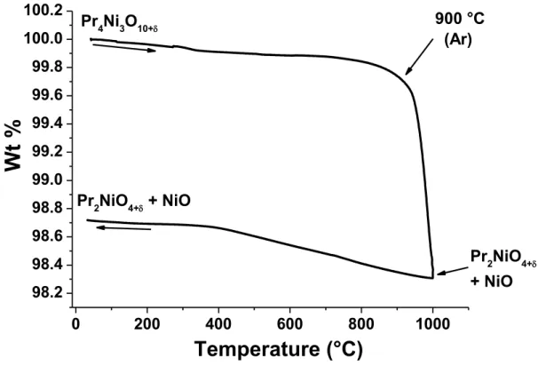
2 0 200 400 600 800 1000 98.2 98.4 98.6 98.8 99.0 99.2 99.4 99.6 99.8 100.0 100.2 Pr2NiO4+ + NiO Pr4Ni3O10+ Pr2NiO4+ + NiO 900 °C (Ar)
Wt %
Temperature (°C)
Fig. S2. Thermal variation of weight loss under argon atmosphere.
0 100 200 300 400 500 600 700 800 10.03 10.04 10.05 10.06 10.07 10.08 10.09 10.10 10.11
Ox
yg
en
Co
n
te
n
t
(10+
)
Temperature (°C)
10.03 10.04 10.05 10.06 10.07 10.08 10.09 10.10 10.11(a)
under argon
Fig. S3. Thermal variation of the oxygen content (10+) under argon (30 °C ≤ T ≤ 800 °C).
3
Fig. S4. Morphology of as-prepared powder after synthesis by GNP.
Fig. S5. Polarization resistances, Rp, measured at 600 °C under air on the half cells
prepared by two-step sintering process at 1000°C/2h/O2, 1050°C/2h/O2 (+ 950
°C/6h/O2), 1150°C/1h/O2 (+ 950 °C/6h/O2) and 1200°C/1h/O2 (+ 950 °C/6h/O2) and
4
Fig. S6. X-ray diffractogram of half cells after sintering at 1150 °C for 1 h under O2 (+
950 °C/6h/O2).
20
25
30
35
40
45
50
55
60
as prepared powder Co-sintered half cell at 950°C/2hunder airafter measurements
In
te
n
si
ty
(
a.
u
.)
2 - Theta (°)
CuK Pr4Ni3O10+ Pr6O11Fig. S7. X-ray diffractograms after EIS measurements performed by co-sintering technique (comparison with powder).