by Habs M. Moy
M.S. Aerospace Engineering, University of Cincinnati, 1991 B.En. Mechanical Engineering, Cooper Union, 1989
Submitted to the System Design & Management Program In Partial Fulfillment of the Requirements for the Degree of
Master of Science In Engineering & Management
at the ASSACHUSETTS INSTITtE
OF TECHNOLOGY Massachusetts Institute of Technology
February 2000
LIBRARIES
@ 2000 Habs M. Moy, All Rights Reserved
The author hereby grants to MIT permission to reproduce and to distribute publicly and electronic copies of this thesis document in whole or in part.
Signature of Author
Certified
Habs M. Moy System Design & /nagement Program January 14, 2000
' Kevin N. Otto
Robert N. Noyce Associate Professor of Mechanical Engineering Product Portfolio Definition Thrust Leader, Center for Innovation in Product Development Thesis Supervisor
Thomas A. Kochan LFM/SDM Co-Director George M. Bunker Professor of Management
Accepted by
rau P. Lagace LFM/SDM Co-Director Professor of Aeronautics & Astronautics and Engineering Systems Accepted bv_________-_______
I
_
1. ff - 1
Commercial Gas Turbine Engine Platform Strategy and Design
by Habs M. Moy
Submitted to the System Design & Management Program on January 14, 2000 in Partial Fulfillment of the Requirements for the Degree of Master of Science in
Engineering & Management
Abstract
Product development challenges companies to produce designs that meet customer requirements yet, that are within their technological and financial
means to do so. The proliferation of customized or unique designs may tax the resources of a firm if product variety cannot be achieved in a cost-effective manner. A product platform strategy allows a set of core elements or
subsystems to be shared across all or part of a company's product portfolio, while design flexibility allows differentiated functions to satisfy specific customer needs. A framework for identifying potential platform elements from among key system design variables is provided. This framework supports the hypothesis that system design variables with low normalized coupling and low normalized variation across a set of conceptual product designs should be considered as potential platform elements. A system level approach for identifying the coupling and variation of these elements is facilitated through the formulation and use of a modified quality function deployment (QFD) mapping procedure. Normalized coupling is quantified as the relative importance of relationships between
stakeholder needs, system requirements and system design variables, divided by a ranking of the difficulty in their achievement. Normalized variation of system design variables from a sample of parameter data is calculated as the standard deviation divided by the mean. The proposed framework and hypothesis is validated with a case study of the Pratt & Whitney PW4000 family of commercial gas turbine engines where predicted platform elements were consistent with actual design choices.
Thesis Advisor: Kevin N. Otto
Acknowledgments
I cannot begin to acknowledge all the people who have made this work possible.
It certainly includes all the people and events that have shaped the last two years in the System Design & Management Program, but I would be remiss if I did not also acknowledge those who have been a constant anchor in my personal life. Thanks go to UTC/Pratt & Whitney for sponsoring me to this program and to the following individuals who supported the work that went into this research:
Franklin Gattis, Karl Hasel, Jeffrey Hathaway, Billie Jones, Craig Lewis, Kent Lyons, Walter Malkauskas, Ben Mancuso, James Panaia, Joe Presing, Thomas Rogers, Robert Saia, Austin Smith, Paul Smith, Reid Smith, Yasar Tanrikut, William Taylor, George Titterton and Barry Wood. Special thanks go to George Aronstamm who spent many a late afternoon passing on the gas turbine engine
knowledge he has accumulated with over 30+ years of service at Pratt &
Whitney. Thanks also go to Michael Chemerynski and Frank Gass for supporting me through two years of two shift workdays.
Thanks go to MIT and the Center for Innovation in Product Development for fostering research that is pertinent for today's industry. Special thanks go to my advisor, Kevin Otto, for his guidance and vibrant attitude towards this effort, and to Javier Gonzalez-Zugasti for all the philosophical discussions on platforms that gave me the perspective with which to look at gas turbine engines. Best wishes to Javier for a successful doctoral defense!
Perhaps the richest part of this entire learning experience was working with and learning from my fellow colleagues in the SDM program. Learning from all of you first hand about the inner workings of the various industry leading companies you represent, is far more valuable than reading about it in a case study or business journal. Thanks to all of you for making this experience come alive. Best wishes for your continued success.
I want to thank my family for their continuous support. Thanks to Yvette, Evelyn
and Yvonne for taking care of things on the home front while I was occupied. I want to thank my significant other, Ying, for her support, patience and
heartwarming smile through two years of distance relationship held concurrently with two years of SDM distance learning. We are finally at the end of this part of the journey. The next part is about to begin.
My most heartfelt acknowledgments go to my parents for their investments in me
since the day I was born. Those investments of care, guidance and support have paid back handsomely with 3 university degrees ... all tuition free. How about that for a measure of return on investment? Thanks Mom and Dad. This third
Table of Contents
1 Introduction... 8
2 Related W ork... 12
2.1 Product Portfolio Architecture... 12
2.2 Examples of Product Platform s ... 14
2.3 Product Architecture Concepts ... 15
3 System Architecture of a Commercial Gas Turbine Engine...17
3.1 Airplane System and Engine Subsystem ... 17
3.2 Modularity and Integrality ... 18
3.3 Mechanical & Aerothermodynamic Coupling ... 20
4 Q uality Function Deploym ent (QFD)... 23
4.1 What is QFD? ... 23
4.2 Applying QFD to Identify Platform Elements ... ..25
4.3 Elem ents of the Platform QFD ... 28
4.3.1 Stakeholders and their Needs ... 28
4.3.1.1 Airplane Mission ... 29
4.3.1.2 Reliability ... 30
4.3.1.3 Cash Operating Cost... 30
4.3.1.4 Environmental ... 31
4.3.1.5 Recurring Cost (Manufacturing)... 31
4.3.1.6 Non-Recurring Cost Spent to Launch (Technology)... 31
4.3.1.7 Non-Recurring Cost Spent from Launch to Certification (E&D)... 31
4.3.1.8 Entry into Service (EIS) Date ... 32
4.3.2 System Requirements ... 33 4.3.2.1 Airplane Integration ... 34 4.3.2.2 Performance... 34 4.3.2.3 Reliability... 35 4.3.2.4 Environmental ... 36 4.3.2.5 Cost ... .. 37 4.3.2.6 Design ... 37 4.3.2.7 In-Service Operations... 37
4.3.3 System Variables at the Module Level ... 38
4.3.4 Module Flowpath Aerothermodynamic Variables... 40
4.4 QFD Platform Mapping ... ..42
4.4.1 Mapping Stakeholder Needs to System Requirements ... 42
4.4.1.1 Relative Importance of System Requirements... 44
4.4.1.2 Conflicts Between and Among System Requirements ... 44
4.4.1.3 Stakeholder Needs for Different Market Segments ... 47
4.4.1.4 System Requirement Difficulty and Core Competencies... 48
4.4.1.5 Deriving the Normalized Coupling Measure ... 48
4.4.2 Mapping System Requirements to System Variables ... 50
4.4.3 Mapping System Variables to Module Flowpath Aerothermodynamic Variables...51
4.4.3.1 Relative Importance of Module Flowpath Aerothermodynamic Variables ... 53
4.4.3.2 Relative Module Ranking ... 54
4.4.4 Normalized Variation ... 55
4.4.5 Defining Boundaries for High and Low Normalized Coupling and Variation...55
5 Pratt & W hitney Case Studies ... 57
5.1 Sample of 8 Engines... 58
5.2 PW4000 Engine Fam ily... 62
5.2.1 Background... 62
5.2.2 PW 4000-94" Platform Strategy... 63
5.2.3 PW 4000-1 00" and PW 4000-112" Growth Strategy... 65
5.2.4 Validating the Hypothesis with the PW 4000... 66
6 Sum m ary and Conclusions ... 74
7 Recom m endations ... 76
7.1 Conceptual Design Tool... 76
7.2 Extensions of QFD Mapping ... 78
7.2.1 Mapping to Support Structure Part Characteristics... 79
7.2.2 Mapping to Key Process Operations... 80
7.3 Other Applications... 80
7.3.1 Value Engineering ... 80
7.3.2 Military, Small Commercial and Industrial Engines ... 81
7.4 Multi-Project Management as a Portfolio Planning Strategy ... 81
7.4.1 Push versus Pull Market... 82
7.4.2 Product Lifetime & Certification Costs... 83
7.4.3 Production Volume ... 83
7.4.4 Level of Technology Capability... 84
7.5 Strategic Analysis... 84
7.5.1 Core Competencies & the Organization... 84
7.5.2 Porter's Five Forces Model... 85
7.5.2.1 Customers ... 86 7.5.2.2 Suppliers ... 87 7.5.2.3 Competitors... 87 7.5.2.4 Substitutes... 88 7.5.2.5 Barriers to Entry ... 89 References ... 92 G lossary ... 95
List of Figures Figure Figure Figure Figure Figure Figure Figure Figure Figure 1.1: 3.1: 3.2: 4.1: 4.2: 4.3: 4.4: 4.5: 4.6: Figure 4.7: Figure 5.1: Figure 5.2: Figure 5.3: Figure 5.4: Figure 5.5: Figure 5.6: Figure 7.1:
Hypothesis for Assessing Platform Elements ... 8
Airplane Passenger and Range Capabilities ... 17
PW 4000-94" ... . .19
Quality Function Deployment (QFD) Mapping Framework ... 24
Modified QFD Framework for Platform Analysis...26
Exam ple of QFD Mapping ... 27
Phase I - Mapping Stakeholder Needs to System Requirements ....43
Conflicts Between and Among System Requirements...45
Phase I - Sample Mapping of System Requirements to System V ariables ... . . 50
Phase Ill - Sample Mapping of System Variables to Module Flowpath Aerothermodynamic Variables...52
Normalized Coupling and Normalized Variation for the 8 Engine Sample (Module Flowpath Aerothermodynamic Variables)...59
Module Flowpath Aerothermodynamic Variable Classifications for the 8 Engine Sam ple ... 60
Normalized Coupling and Normalized Variation for the PW4000 (Module Flowpath Aerothermodynamic Variables)...67
Module Flowpath Aerothermodynamic Variable Classifications for the PW 4000 ... . 68
Normalized Coupling and Normalized Variation for the PW4000 with a 4.5% Normalized Variation Threshold (Module Flowpath Aerothermodynamic Variables) ... 70
Module Flowpath Aerothermodynamic Variable Classifications for the PW4000 with 4.5% Normalized Variation Threshold ... 71
List of Tables
Types of Modular Architectures ... 16
Stakeholders and their Needs... 29
FAR Part 33 Aircraft Engine Certification Tests ... 32
Propulsion System Requirements... 33
System Variables... 39
Module Flowpath Aerothermodynamic Variables... 41
PW 4000 Family of Engines... 62
Porter's Five Forces... 86
Travel Alternatives Between Hartford, CT and Washington, DC...88
Collaborations in Commercial Gas Turbine Engine Development .... 90
Table 2.1: Table 4.1: Table 4.2: Table 4.3: Table 4.4: Table 4.5: Table 5.1: Table 7.1: Table 7.2: Table 7.3:
1 Introduction
Product development challenges companies to produce designs that meet customer needs, yet that are within their technological and financial means to do so. The proliferation of customized or unique designs may tax the resources of a company if product variety cannot be achieved in a cost-effective manner. One strategy to minimize the costs associated with unique designs is to share
elements or subsystems across all or part of a company's product portfolio, while design flexibility allows differentiated functions to satisfy specific customer needs. The grouping of these shared elements comprise a platform. The key is to
determine which elements or subsystems comprise the platform.
The objective of this investigation is to provide a framework for identifying potential platform elements from among key system design variables. The proposed framework is validated with a case study of commercial gas turbine engines that confirms the hypothesis that system design variables with low normalized coupling and low normalized variation from design to design should be considered as potential platform elements. This proposed hypothesis is illustrated in Figure 1.1, where platform candidates would cluster in Quadrant .
Quadrant III Quadrant IV
s High Do Not .4isk Platform S Quadrant I Quadrant 11 08 Low dr. Platform Risk Low High Normalized Variation (Standard Deviation / Mean)
A system level framework for identifying the normalized coupling and
normalized variation of these elements was facilitated through the formulation and use of a modified quality function deployment (QFD) mapping procedure. Normalized coupling was assessed by quantifying the relative importance of relationships between stakeholder needs, system requirements and system design variables, and dividing these rankings by a ranking of the difficulty in their achievement. Normalized variation of system design variables from a sample of parameter data was calculated as the standard deviation divided by the mean.
Normalized coupling implies that a product attribute or function, which has low coupling and low difficulty, is as likely to be considered a platform element as one that has high coupling and high difficulty. The motivation for platforming an element that has high coupling and high difficulty is to leverage the higher development cost and effort associated with this more difficult element across multiple applications, rather than developing costly, unique solutions over and over for each new product [Robertson and Ulrich, 1998]. Sharing platform elements across multiple products may lead to lower manufacturing costs from economies of scale, lower development costs, and faster time to market to name a few benefits.
In contrast, system design variables that have high normalized coupling and high normalized variation may be poor candidates as platform elements. These variables are predicted to cluster in Quadrant IV of Figure 1.1. Because of their high level of coupling with upstream stakeholder needs and system
requirements, keeping them at a fixed level as platform elements may adversely affect many other system variables. The cost of keeping Quadrant IV variables constant in a platform scenario is the high overall system impact due to the high coupling. This system cost may outweigh the elemental cost savings benefit. Since these variables are not difficult to achieve anyway, it may be beneficial and cost effective to allow them to vary as appropriate, so that overall needs and system requirements can be met.
For cases where there is low normalized variation, but high normalized coupling as in Quadrant Ill, there is risk in considering these elements for a
platform. There is a possibility that fixing them in a platform scenario is risky should some future growth potential or unanticipated condition force them to be changed, moving these elements from Quadrant Ill to Quadrant IV. Since these elements are highly coupled, changing them could have a large impact on the overall system.
For cases where there is high normalized variation, but low normalized coupling, there is less risk than the opposite case described in the preceding paragraph because of the low coupling. These variables would cluster in
Quadrant 11. Fixing these parameters at a given level for a platform may have a small overall system effect due to the low coupling. Again, there is always risk that a change in requirements may increase the coupling, moving these variables into Quadrant IV.
The proposed framework and hypothesis was validated with a case study of the Pratt & Whitney PW4000 family of commercial gas turbine engines where platform elements predicted by the model were consistent with actual design choices. The results identified a set of system design variables with low
normalized coupling and low normalized variation that could serve as elements of a commercial gas turbine engine platform and be shared across multiple
products.
Chapter 2 begins with an overview of product portfolio architecture and methods of defining them. A platform is a type of product portfolio architecture and some examples are given to provide the reader with a perspective of existing platform strategies. The chapter ends with a brief discussion of product
architecture concepts as a lead into Chapter 3, which discusses the system architecture of the gas turbine engine and how certain aspects of the engine's architecture may or may not lend themselves to platform considerations.
Chapter 4 introduces QFD and summarizes the methodology used to adapt the traditional QFD framework to perform platform analyses.
To validate the hypothesis set forth above, two case studies involving recent Pratt & Whitney engine designs are discussed in Chapter 5. Following some concluding statements in Chapter 6, Chapter 7 discusses
recommendations for extending the framework presented in this investigation as well as interrelationships and implications between the strategic management of a company and the company's product strategy. Finally, a glossary is included at the end of the document for those who desire further explanation of terms used in this work.
Scattered throughout the text are descriptive examples and what if scenarios, which are provided to clarify some of the concepts and issues
surrounding commercial gas turbine engine platform strategy and design. They are by no means exhaustive explanations, but are primarily included to provide the reader with an appreciation of the issue(s) and to highlight key points. Analogies to other products are also provided, not only to help explain issues specific to gas turbine engines, but also to provide some basis for comparison as to how these analogies apply or could be applied to gas turbine engines.
2 Related Work
To establish a basis for the platform framework presented in this
investigation, it is important to review related work concerning product platforms from both a design perspective as well as a product strategy perspective. The literature contains a number of studies that have been conducted to classify product portfolio architectures such as platforms and recommend ways to define these architectures. Product platforms such as the Sony Walkman and Ford automobiles are examples of how platform strategies have been successfully
implemented and which can provide additional perspectives on what is achievable. The discussion begins with an overview of product portfolio architecture.
2.1 Product Portfolio Architecture
Product portfolio architecture entails defining the way in which members of a portfolio of products share or do not share features. Yu [1998] defines three categories of portfolio architecture: fixed, platform and adjustable. A fixed portfolio architecture is where a single option for a feature is offered across an entire set of products. An example of a fixed architecture is a videocassette case. A platform portfolio architecture is where multiple options for a feature are offered across an entire set of products. An example of a platform architecture is Chrysler's LH platform where the Intrepid, Eagle, Concorde and LHS all share a common body frame construction, but have different styling features for different market segments. An adjustable, mass customization portfolio architecture is where multiple options are offered through a single design, which can be
customized by the user. An example of an adjustable portfolio architecture is a hair dryer with multiple heat settings.
Recent research has focused on customer needs as a basis for product portfolio definition and planning. Moore [1999] proposes conjoint analysis as a way to quantify customer preferences for different combinations of product
attributes. Yu [1998] defines a methodology for product portfolio definition of instant film cameras based on customer needs and accounting for the possibility that these needs may change over time. Roberson [1998] proposes a product attribute clustering technique to define appropriate combinations of automobile platform elements. These investigations all seem to have focused on consumer products where variety is needed to fulfill customer needs.
Another product portfolio architecture strategy is based on some measure of product performance. Product performance can be defined as how well a product implements its intended functions [Ulrich, 1995]. Some general examples of product performance characteristics are speed, efficiency, life, accuracy and noise. Krishnan [1998] proposes a model based approach for
planning and developing a product family where customers choose products based on some measure of performance.
In another product performance based example, Gonzalez-Zugasti [1998] proposes a methodology for optimizing the product portfolio architecture of a family of future spacecraft fielded by the Jet Propulsion Lab. The methodology begins with a point design calculation for each of the different spacecraft
missions. The proposed hardware and system performance characteristics of all the point designs are then reviewed and areas of similarity or commonality are identified. These particular components or actual design values are held
constant as each of the point designs is then re-evaluated in terms of being able to meet their specific mission requirements. If mission requirements cannot be met, then a negotiation process may take place to arrive at a mutually optimal solution in light of different mission constraints. If mission requirements are met, then those elements can be considered part of a platform.
The framework proposed in this investigation is based on an approach similar to that of the JPL case where the variation of key system design variables from a sample of engines is calculated. A modified QFD mapping procedure is implemented to quantify the degree of coupling between stakeholder needs, system requirements and system design variables as well as the difficulty in their
achievement. Platform elements are then identified as those variables with low normalized coupling and low normalized variation.
2.2 Examples of Product Platforms
The idea of platforms as a strategy for defining product portfolio architecture is not new. Examples of product platforms include the Sony Walkman [Sanderson and Uzumeri, 1995], and Ford's 4.6L SOHC V-8 engine
[Hagen, 1990] and vehicle platforms [Nelson et al., 1998]. The benefits of product platforms include reduced engineering and development costs, quicker time to market, economies of scale due to increased volume of standard parts,
and common design concepts. The case of the Sony Walkman and Ford V-8 engine illustrate two different product platform strategies, where the former is based on topological design changes, while the latter focuses on fundamental, internal design changes.
In the early 1980's, Sony developed 3 basic platforms on which all subsequent Walkman models were built. These platforms focused on two key areas including miniaturization, which affected battery size, and high sound quality systems. With these 3 platforms, Sony offered as many as 20 new models each year and almost 250 US models in the 1980's. Approximately 85% of these 250 models were the result of topological design changes, or cosmetic changes to the outside case and minor re-arrangement of existing features. Sony's success with the Walkman was the result of providing product variety to several market niches. In fact, they offered more models than the competition during this period. This platform strategy focused on providing product variety through topological design changes, while only incrementally improving the performance of the basic platforms [Sanderson and Uzumeri, 1995].
The case of Ford's V-8 engine platform is more analogous to that of the gas turbine engine, where the primary means of providing product variety is not necessarily with topological design changes as in the case of the Sony Walkman, but with design changes to the internal workings of the machinery to enhance performance. Ford's engine platform strategy was to design a family of engines
that were to be used in a variety of large and luxury vehicles based on common combustion chambers, valvetrains and basic structure to allow ease of
interchangeability. The use of the same component in multiple products can be defined as component standardization [Ulrich, 1995]. Similar components within
engine families were also shared such as cylinder blocks, aluminum cylinder heads, camshafts, water and oil pumps, and fasteners. Maintaining key
characteristics of a particular engine platform, such as bolt patterns, bore spacing and journal sizes were also part of the platform strategy. As a result, it was estimated that the family of engines would share 75% of all parts [Hagen, 1990].
Maintaining key characteristics is also the basic strategy for Ford's Global Architecture Process (GAP) for entire vehicle platforms [Nelson et al., 1998]. Hardpoints are defined for each platform and consist of master location holes and surfaces, weldlines, and wheelbase and overhang variation ranges. Even with these hardpoints, there is still flexibility to build variety into products of a given platform family. The rationale for maintaining hardpoints is to support high volume vehicle production with flexible manufacturing lines. This vehicle platform strategy is more analogous to the Sony Walkman case than it is to the V-8
engine case, because product variety is provided by topological design changes like body panels, cabin size as well as other attributes distinguishable by the consumer.
The Sony Walkman and Ford V-8 engine/vehicle cases illustrate different product platform strategies. Chapter 5 discusses the Pratt & Whitney case study of the PW4000 engine family and similarities to the Sony and Ford cases. The next section discusses some basic concepts of product architecture that may or may not lend themselves to a platform strategy.
2.3 Product Architecture Concepts
Given the examples of product platform strategies and how they may be defined, it is important to understand some fundamental concepts of product
architecture that may or may not lend themselves to a platform strategy. Product architecture can be categorized as either modular or integral [Ulrich, 1995]. An
architecture that is modular has functional elements that have a one-to-one mapping to the physical components of the product and where interfaces between components are decoupled. Two components are considered
decoupled if a change made to one component does not require a change to the other component in order for the entire product to work correctly. In contrast, an architecture that is integral has functional elements that have more than a one-to-one mapping to physical compone-to-onents and/or have coupled interfaces between components.
There are various types of modular architectures, namely slot, bus and sectional [Ulrich, 1995]. These are summarized in Table 2.1.
Table 2.1: Types of Modular Architectures
TypeDefinition
E
xamplesA car radio versus speedometer. The
Slotinterface and cannot be car radio has interfaces that do not
interchanged. allow it to be plugged into the same
interface as the speedometer. Dell Cpi laptop computer where both
Various components have the same the 3.5" disk drive and CD-ROM drive
Bustype of interface and can connect to a have the same interface that allows
common component. one to be interchangied with the other
in the same rece tacle. Components all have the same
S cin l interfaces with no sing e element to Ppnscinlsfsadofc
Sectional which all the other components prtin. attach.
These examples illustrate how some products lend themselves to one form of platform architecture over another.
The next chapter sets the stage for the discussion on how platform
elements are identified with the modified QFD mapping by providing perspectives on the system architecture of a gas turbine engine. Included in this discussion is a description of basic system architecture, issues of modularity and integrality, and coupling.
3 System Architecture of a Commercial Gas Turbine
Engine
3.1 Airplane System and Engine Subsystem
From the perspective of an air transportation vehicle, the gas turbine engine is a subsystem of an airplane system. All airplane engines have the same basic functionality of producing thrust to propel an airplane into the air and over a design range with a specified payload. Some secondary engine functions that support airplane functions include providing cabin air, electrical power to airplane systems, and pressurization for airplane hydraulic systems through airplane/engine interfaces. Figure 3.1 illustrates the range and passenger capacities of Pratt & Whitney powered narrowbody and widebody airplanes [Jackson, 1995 & 1997]. IA E-Z 500 450 400 350 300 250 200 150 100 50 0 0 B747-400/PW4056 x B777-2OO/PW4084. B777-300/PW4098 A330-300/PW4168 B777-2001GW/PW4090 A300-600/PW4158 B767-300/PW4056 A330-200/PW468 A31 O-300/PW41 52 + 9 B767-300ER/PW4060 A321/V2633-A5A B757-200/PW2040 @ B767-200ER/PW4056 A
A31 9N2522-A5 A A320N2525-Al
1000 2000 3000 4000 5000 6000
Range (nautical miles)
7000 8000 9000 10
Engines can provide different thrust levels for different airplane
applications. Thrust variation is achieved as a result of the aerothermodynamic and mechanical design of the engine's turbomachinery that includes the rotating blades and stationary vanes, as well as the associated support structure.
Support structure includes major parts such as disks, cases, seals, bearings and shafts.
Airlines can choose between and among engines offered by different manufacturers, since the engine is an option on the airplane. For example, an airline that purchases a Boeing B777 has the option of choosing either Pratt & Whitney PW4000, General Electric GE90 or Rolls Royce Trent 800 series engines. Here, all three engine manufacturers supply engines with roughly the same rated takeoff thrust, but that may be differentiated by their degree of fuel efficiency, weight, and reliability as examples. What allows three different engine types to interface and be used on the same airplane is the engine buildup unit
(EBU).
3.2
Modularity and
Integrality
A commercial gas turbine engine has attributes of both modular and
integral architectures. The modular construction of the engine is such that the major components, typically referred to as modules, can be bolted to each other to form the entire engine. Major engine modules include
. Fan
. Low Pressure Compressor (LPC)
. High Pressure Compressor (HPC)
. Combustion Chamber (also referred to as the burner)
. High Pressure Turbine (HPT)
. Low Pressure Turbine (LPT)
Figure 3.2 is a cutaway illustration of the PW4000-94" showing the major modules and their relative position to one another [http://www.pratt-whitney.com/engines/galery/g.pw4000.94cut.htm].
LOW PRESSURE COMPRESSOR FAN ILET CASE Figure 3.2: PW4000-94"
The high pressure turbine, as an example, is a module that is the
assembly of its constituent parts including blades, disks, seals and a case. The high pressure turbine module as a whole is attached to the diffuser case, which houses the combustion chamber on the upstream end, and the low pressure turbine module on the downstream end.
Although the engine is modular in construction, its functionality on the module level is integral both in terms of the many to one mapping of functional elements to physical components, as well as coupled interfaces between
modules. In terms of basic engine functionality, compression is accomplished by the fan, LPC and HPC, fuel-air mixing and burning is accomplished by the
combustion chamber, and expansion is accomplished by the HPT and LPT to all to create thrust. However, there is a many to one mapping of functions to a
particular module. For example, functions of the HPC not only include
compressing air, but also providing secondary flow to other parts of the engine as well as to the airplane, providing airflow acceptable to the downstream burner module, providing support for internal turbomachinery, accepting torque from the shaft connected to the HPT, and driving an accessory gearbox with assorted pumps and generators.
In terms of coupled interfaces, the engine is integral in the sense that a change to one module affects other engine modules. Ulrich [1995] refers to different types of coupling including those of geometry and heat. These types of coupling found in gas turbine engines are discussed in the next section.
3.3
Mechanical & Aerothermodynamic Coupling
Geometric or mechanical coupling occurs where certain modules are mechanically connected to the same shaft and so turn at the same speed. The high pressure compressor (HPC) module and high pressure turbine (HPT) module are connected to the same shaft, which rotates at high speed. The combination of the HPC and HPT modules is typically referred to as the high spool or engine core. Sandwiched between the HPC and the HPT is the combustion chamber which is also considered to be part of the core. An example of mechanical coupling in the core is where a change in the exit diameter of the HPC case requires a change to the inlet of the diffuser case to which it is connected.
As in the core, the combination of the fan, LPC and LPT modules, typically referred to as the low spool, are connected to a different shaft that rotates at a speed slower than that of the high spool. The combination of the fan, LPC and LPT is typically referred to as the low spool. Although the low and high spools can be considered mechanically decoupled, since each spool is connected to a different shaft and turns at a different speed, there are still interactions between the spools due to aerothermodynamic coupling.
Aerothermodynamic coupling comes from the fact that air and exhaust gases travel through a continuous flowpath formed by the turbomachinery of all
the engine modules, from the inlet to the exit of the engine. The exit conditions of mass, momentum and energy in the form of pressure, temperature and flow from one module serve as the entrance conditions for the following module. In addition, a change in a flowpath condition for a module on one spool may affect another module on the same or the other spool because of this continuous flow from one module to the next.
Coupling effects are not necessarily bad. Quantification of module to module parameter coupling can be used during the engine development process to optimize overall system performance. The coupling between modules is
typically quantified by what are referred to as influence coefficients or trade factors. For example, if an engine test reveals that fuel efficiency goals are not being met, influence coefficients generated from powerplant performance simulations can be used to compare actual parameter shifts with predicted parameter shifts in order to determine which module(s) are key contributors to this deficiency. This information can then be used to determine what module improvements are needed in order for the engine to meet overall system requirements.
In contrast, coupling can also be detrimental when a change to one aspect of the engine adversely affects one or more aspects of another part of the
engine. For example, although the low pressure compressor (LPC) and high pressure compressor (HPC) are not mechanically coupled because they are connected to different shafts, they are still aerothermodynamically coupled because they share a common interface. LPC exit conditions of pressure,
temperature and flow serve as the entrance conditions to the HPC. Good engine design will minimize the coupling between these modules such that a surge condition in one does not exacerbate a surge condition in the other. An engine surge is where the compression system has lost its ability to compress air and there is a momentary reversal of flow towards the front of the engine instead of
rearward. This is an example of the desire to minimize the coupling between modules.
Coupling between and among engine modules both mechanically and aerothermodynamically complicates the issue of a platform. Swapping a module from one engine type to another in a building block philosophy first requires that
the mechanical interface is compatible, e.g. bolt locations, diameters and shaft size. Even if the mechanical interface is compatible, the aerothermodynamic coupling between and among modules may prevent this swapping strategy from allowing the entire engine to meet system requirements.
Because the traditional approach of defining platform elements as those which have little or no coupling at the interface or have a one-to-one mapping of form to function, are not entirely appropriate for a commercial gas turbine engine which is functionally integral, as well as mechanically and aerothermodynamically coupled, an alternative approach is needed. The next chapter introduces quality function deployment (QFD) as a framework for assessing a form of system level coupling that not only captures the physical coupling described above, but also the relationships between key system design variables and the stakeholder needs and system requirements that drive them. Quantifying the degree of coupling between needs, requirements and system design variables as well as their difficulty in achievement, will help to identify the system level effect of keeping key design variables constant or within a certain range of variability in a platform scenario. Identifying these key design variables is then the first step in identifying potential platform elements in an integral and coupled architecture such as the gas turbine engine.
4 Quality Function Deployment (QFD)
4.1 What is QFD?
This investigation utilized QFD to systematically identify key elements of a gas turbine engine product platform. QFD was reported on by Hauser and
Clausing [1998], but was originally based on the quality tables developed by Professor Mizuno at the Tokyo Institute of Technology for Mitsubishi Kobe Shipyards in 1972. QFD is a means to ensure that high level needs and requirements flow down or are deployed to the design and manufacture of various product components. QFD has been used as a system engineering tool for requirements management, tracking and traceability. It has been used in the design of complex systems such as spacecraft and military airplanes [Boppe,
1998]. Xerox used QFD in the design of their successful Lakes digital document
platform to "deploy the voice of the customer to the factory floor' [Paula, 1997; Elter, 1998].
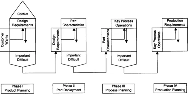
Figure 4.1 [Quality Function Deployment Implementation Manual, 1989] shows the QFD framework beginning with customer wants or needs and progressing to a series of 4 mappings first to design requirements, then to part characteristics, key process operations, and finally to production requirements.
Conflict
Design Part Key Process Production
Requirements Characteristics Operations Requirements
E g 0
Important Important Important
Difficult Difficult Difficult
Phase I Phase 11 Phase III Phase IV
Product Planning Part Deployment Process Planning Production Planning
Figure 4.1: Quality Function Deployment (QFD) Mapping Framework
Each deployment phase in Figure 4.1 is a matrix mapping of relationships between row and column categories. A relationship is indicated at the intersection of a row and column and is interpreted as the importance of a column category in achieving the row category, relative to the influence of other column categories in influencing that same row category. The relative
importance of these relationships is typically captured on a 1 to 10 scale, with 1 denoting low importance and 10 denoting high importance. An organization's experts are consulted to provide the relative importance relationships.
In the end, the relative importance of each column category can be
obtained. These relative importance rankings can then be used as a roadmap to indicate where the organization should focus its resources and attention at each phase. A difficulty ranking can also be assessed against each of the column categories. This can be used to highlight areas that may require additional
resources or attention. Difficulty assessment combined with relative importance rankings can then be used to guide the organization's strategy during the product development process.
Phase I of the QFD mapping framework is referred to as the House of Quality. It is at this stage where customer wants are translated into design
requirements. The proverbial "roof" of the House of Quality captures the conflicts between design requirements, where achieving an optimal level for one design requirement can lead to a suboptimal level for another requirement. For
example, if one considers the generic requirements of performance and cost, a high performance product may cost more to develop than a low performance product because of extra features and capabilities. Likewise, low cost may imply low performance. Thus, a requirement to achieve better performance comes at the expense of cost and vice versa. These requirements work in opposite or conflicting directions.
Each successive phase of deployment is driven by the preceding set of requirements or variables. In other words, the requirements or variables are deployed to successive phases. An example of how QFD can be used during detailed design is when a key process operation in Phase Ill of Figure 4.1 cannot
be accomplished due to the limitations of an existing manufacturing process. The mapping will indicate what key part characteristics in Phase II are affected
and may need to be altered so that the part can be manufactured, as well as what design requirements in Phase I may be affected. One can thus trace the upstream or downstream effects of such changes.
4.2 Applying
QFD
to Identify Platform Elements
The reason why QFD was chosen as a framework to analyze platform elements was because of its ability to capture not only physical coupling, but also the system level coupling of customer wants, design requirements, part
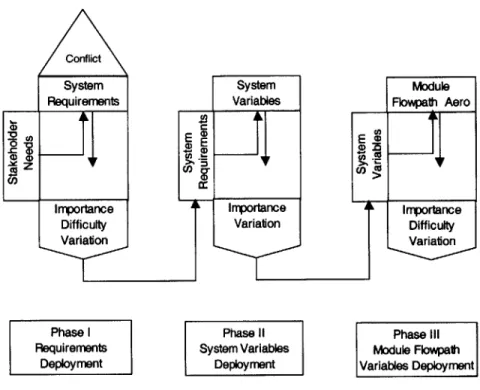
characteristics, key process operations and production requirements. The traditional QFD framework discussed in the previous section was modified for this investigation and was subsequently used to identify potential platform elements based on system level normalized coupling and normalized variation. The modified QFD framework is presented in Figure 4.2.
Conflict System Requirements 0 00 Importance Difficulty Variation Phase I Requirements Deployment System Module
Variables Flowpath Aero
E E) C~CO Importance Importance Variation Difficulty Variation Phase Il Phase il
System Variables Module Flowpath Deployment Variables Deployment
Figure 4.2: Modified QFD Framework for Platform Analysis
The system level coupling between stakeholder needs, system requirements, system variables and module flowpath aerothermodynamic variables is quantified through the identification of relationships between successive mappings and the importance of each relationship. The ranking schemes discussed in Chapter 4.4 allow the relative importance of each
relationship to be captured.
Phase I of the modified mapping illustrated in Figure 4.2 is consistent with the traditional QFD mapping found in the previous section where stakeholder needs are mapped to requirements. For this investigation, stakeholder needs are deployed to what is referred to as system requirements. The difficulty associated with each system requirement is also assessed.
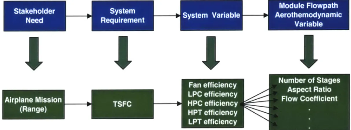
Because of the modular construction of the engine, system requirements are allocated to each of the modules, hence Phase 11 mapping from system requirements to system variables. For example, a typical system requirement may be for a certain level of thrust specific fuel consumption (TSFC), which
satisfies an airplane mission stakeholder need for airplane range as illustrated in Figure 4.3. Although TSFC is a system requirement, each module is expected to operate at a certain level of efficiency so that the entire engine can meet the
TSFC requirement. In this way, the system requirement of TSFC is allocated to
the system variable of module efficiency across all the engine modules.
Stakeholder Requ emen Sysem Variable- Aerothemn narn c
Figure 4.3: Example of QFD Mapping
Unlike Phase 1, Phase I does not include a separate assessment of system variable difficulty in this investigation, because system variables at the module level essentially inherit the difficulty deployed from the system requirements.
Phase Ill of the modified QFD mapping is from system variables to module flowpath aerothermodynamic variables, which are key design variables that are associated with each of the engine modules. Extending the example of the
TSFC system requirement cited above, the system variable of HPC efficiency is
achieved by defining module flowpath aerothermodynamic variable levels such as number of stages, blade aspect ratios, flow coefficients as well as others. System variables from Phase 11 therefore drive module flowpath
aerothermodynamic variables in Phase Ill.
A level of difficulty is assessed for each engine module in Phase Ill and
applies to all the flowpath aerothermodynamic variables associated with that particular module. This difficulty ranking can be based on resource requirements
for personnel, as well as module hardware and non module hardware required during development. As discussed in the introduction, the degree of difficulty is used as a discriminator for identifying platform elements so that they can be leveraged across multiple products. This can reduce subsequent product development effort and cost.
What differentiates the modified QFD framework for platform analysis from the traditional QFD is the quantification of parameter variation at each phase of the mapping. Later sections discuss how the normalized variation of actual aerothermodynamic design data is calculated and how potential platform
elements are identified for Phase Ill of this mapping process. Knowing the level of normalized variation as well as normalized coupling then allows platform elements to be identified.
A detailed description of different elements for each phase of the modified QFD mapping used to identify platform elements is described in the next section.
These include stakeholder needs, system requirements, system variables, and module flowpath aerothermodynamic variables.
4.3
Elements of the Platform QFD
4.3.1 Stakeholders and their Needs
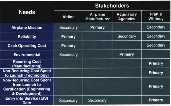
Pratt & Whitney uses a balanced scorecard approach to design engines
[Kaplan and Norton, 1996]. Engine designs are driven by the needs of many stakeholders including airlines, airplane manufacturers, regulatory agencies as well as Pratt & Whitney. Airlines are the end user of Pratt & Whitney engines. Airplane manufacturers consider the engine to be an airplane subsystem.
Regulatory agencies like the Federal Aviation Administration (FAA), International Civil Aviation Organization (ICAO), and Environmental Protection Agency (EPA) define policies and guidelines to protect the public and the environment. Finally, Pratt & Whitney, like any other company, is in the business to make a profit.
Table 4.1 lists the stakeholder needs used in Pratt & Whitney's balanced scorecard approach and who the primary and secondary stakeholders are. Below is a detailed description of stakeholders and their needs.
Table 4.1: Stakeholders and their Needs
4.3.1.1 Airplane Mission
From Pratt & Whitney's perspective, the airplane manufacturer is the primary stakeholder in ensuring the airplane system satisfies its defined mission so that the airline as the secondary stakeholder is satisfied. Elements of the airplane mission which are made possible in large part by the propulsion system include the design range, typical mission length, takeoff gross weight, and the amount of fuel burned. Pratt & Whitney is a secondary stakeholder in the sense that in order for the airplane manufacturer to even consider it a viable contender for an airplane application, its proposed engine offering has to be competitive in achieving the airplane mission. Not being competitive could mean exclusion from consideration. The airplane manufacturer does not have to offer a particular manufacturer's engine as an option to the airline.
4.3.1.2 Reliability
Airlines are the primary stakeholder for engine reliability, although the FAA may become a more vocal stakeholder when flight safety issues have the
potential to adversely affect the flying public. Reliability is the ability of the engine to operate safely and according to its original design intent. Engine reliability is typically measured in terms of in-flight shutdowns, unscheduled engine removals, and delays and/or cancellations.
When engine reliability poses a severe safety hazard, the FAA may
intervene and mandate that certain rectifying actions be taken to minimize risk to the flying public. Poor reliability also increases an airline's direct and indirect operating costs when it has to fix these problems. It may also lower their revenues when flight delays or cancellations decrease passenger satisfaction.
In many ways, Pratt & Whitney is also a secondary stakeholder, because the reliability of the engine influences the amount of post certification engineering
(PCE) effort required to resolve these problems. Given limited budgets, this may
impact the funding available for new engine development programs. Poor engine reliability may also influence an airline's decision not to buy current or future engines from a given manufacturer, because reliability problems like delays and cancellations can result in lost revenues from low customer satisfaction.
4.3.1.3 Cash Operating Cost
Airlines are the primary stakeholder for cash operating cost (COC). COC includes costs associated with operating the engine such as total maintenance cost (TMC) and the cost of fuel burned. The stakeholder need is to minimize
COC via low maintenance costs and fuel efficient engines.
Pratt & Whitney can also be considered a stakeholder when it offers fixed price maintenance contracts to airlines. This is where Pratt & Whitney maintains an airline's fleet of engines and charges a certain maintenance rate based on the
number of hours the engines are operated. If actual maintenance costs exceed negotiated contract levels, Pratt & Whitney stands to lose profit. In addition, if
maintenance costs are too high relative to the competition, Pratt & Whitney stands to lose market share for these maintenance contracts.
4.3.1.4 Environmental
Regulatory agencies such as the FAA, ICAO and EPA are the primary stakeholders acting on behalf of the public for ensuring that engines are environmentally friendly when they are operated, as well as when they are manufactured or repaired. There are published guidelines for allowable
emissions and noise levels. Airlines are secondary stakeholders because they are penalized for operating engines that violate local emission and noise
restrictions.
4.3.1.5 Recurring Cost (Manufacturing)
Recurring cost is the cost for Pratt & Whitney to manufacture each engine. As such, Pratt & Whitney is the primary stakeholder for ensuring that recurring costs are minimized in order to maximize profit margins.
4.3.1.6 Non-Recurring Cost Spent to Launch (Technology)
Again, Pratt & Whitney is the primary stakeholder for this need. Non-recurring costs include the development of technologies that will allow the engine to achieve the airplane mission. New technologies must demonstrate a certain level of maturity before they can be considered for inclusion in a new engine program. It is the cost associated with the maturation of these technologies that comprises this cost.
4.3.1.7 Non-Recurring Cost Spent from Launch to Certification (E&D)
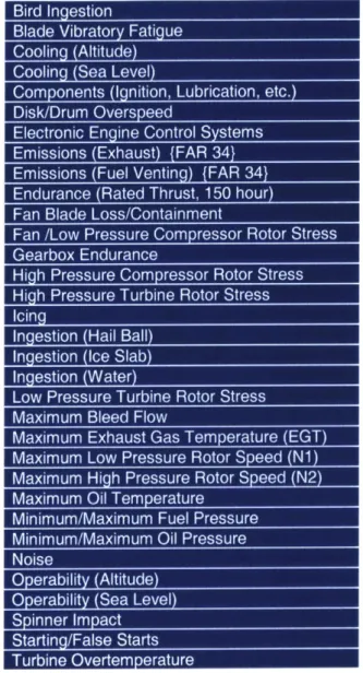
Engineering and development (E&D) costs include that for manpower, engine hardware, non-engine related equipment, and testing to ensure the engine meets airplane mission requirements as well as passes FAA tests to be certified as airworthy. Listed below are FAA tests prescribed by Federal Aviation Regulations (FAR) Part 33, Airworthiness Standards: Aircraft Engines
Table 4.2: FAR Part 33 Aircraft Engine Certification Tests
E&D is essentially an affordability issue for Pratt & Whitney. There may be
instances when a development program may be technologically ready for launch into full scale development and certification, but may end up being delayed because of limited resources.
4.3.1.8 Entry into Service (EIS) Date
This is the date when the launch airline begins operating airplanes in revenue service carrying passengers. This date is mutually agreed to by the launch customer, airplane manufacturer and various suppliers, of which Pratt & Whitney is an engine supplier. During the elapsed time between formal program
launch and EIS date, the development organizations must not only develop and test hardware that meets airplane mission requirements, but also ensure the engine passes FAA tests to be certified as flightworthy.
EIS date influences what technology can be incorporated into an engine
design, whether or not sufficient resources are available during the given development period, and whether or not the engine can meet its requirements when airlines begin revenue service operations. Although there are various stakeholders, Pratt & Whitney is the primary stakeholder.
4.3.2 System Requirements
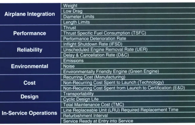
To ensure stakeholder needs are fulfilled, system requirement categories are defined and target levels are set prior to program launch. Pratt & Whitney uses the system requirement categories and subcategories listed in Table 4.3.
Table 4.3: Propulsion System Requirements
During the product development process, actual system requirement levels are tracked relative to target levels. Shortfalls are identified and action plans are
implemented to ensure the engine meets all requirements. For example, the engine's thrust specific fuel consumption (TSFC) is a performance requirement, which is a measure of how efficiently the engine burns fuel to produce a given thrust level. A target TSFC level is defined such that the stakeholder needs for the airplane to fly a certain range with a given payload, low cash operating cost due to fuel burned, and low recurring and non-recurring costs can all be
achieved. As discussed in Chapter 3.3, a deficiency in TSFC can be isolated to certain parts of the engine, so that specific hardware changes can be
implemented to address the problem. This may mean changing the aerodynamics of the turbomachinery airfoils or reducing tip clearances as example solutions. The sections below describe in greater detail each of the
requirements listed in Table 4.3. 4.3.2.1 Airplane Integration
Requirements in this category involve system level interface issues between the engine and the airplane and include engine weight, drag, diameter limits and length limits. The engine is mounted to the airplane via the pylon. Because the pylon is designed to support a certain load, the engine weight must be kept within these limits. In addition, the diameter of the engine is constrained for wing mounted engines because of the required clearance between the bottom of the engine and the ground. This clearance is necessary to minimize ground vortex as well as foreign object ingestion which may adversely affect engine operation. Length limits are important since they affect how and where the engine is mounted to the pylon.
4.3.2.2 Performance
Requirements in this category involve the primary function of the engine, which is to generate thrust to propel an airplane in flight. Thrust is the force that
propels an airplane at a specified speed and altitude throughout its flight envelope. Other requirements include thrust specific fuel consumption (TSFC) and performance deterioration rate. TSFC is a measure of how efficiently the engine burns fuel in terms of rate of fuel burned per pound of thrust generated.
Performance deterioration rate is how quickly an engine's fuel efficiency changes over time and is typically measured in %TSFC change per a given number of cycles. Worse TSFC means that the engine is operating less efficiently and has to burn more fuel to achieve the same thrust level. For long range airplane
missions, fuel burn is critical given the finite amount of fuel the airplane is designed to carry.
4.3.2.3 Reliability
Requirements in this category are associated with the engine's ability to operate according to its original design intent. Engine reliability is measured in terms of in-flight shutdown rate (IFSD), unscheduled engine removal rate (UER), and delay and cancellation rate (D&C). Both the in-flight shutdown and
unscheduled engine removal rates are measured as events per one thousand flight hours. The delay and cancellation rate is measured as events per one hundred airplane departures. Although these reliability metrics are applicable to airplane related problems as well, the descriptions below focus on engine related problems.
An in-flight shutdown is when the pilot terminates fuel flow to the engine.
A pilot may elect to shutdown an engine when its continued operation after an
anomalous operating condition is deemed to have the potential of causing further damage to the engine or creating a safety hazard for the airplane. Examples of conditions that may cause an in-flight shutdown include a bearing failure which may cause an oil filter clog indication and high vibration, compromised bearing compartment seal which may cause an indication of low oil pressure, low oil level and/or high oil temperature, and fractured airfoils that may cause a surge and high vibration. Although an engine may be shutdown, the airplane can still continue the flight if the other engine(s) are operating normally.
An unscheduled engine removal occurs when the engine's inability to continue functioning within normal operating guidelines causes it to be removed for repair or refurbishment. This can result from an in-flight shutdown, the inability to correct a problem even after on-wing troubleshooting, as well as an
engine durability problem where a part deteriorates or fails before reaching its predicted design life. An unscheduled engine removal is in contrast to a scheduled removal where an airline deliberately plans to remove an engine for scheduled maintenance or rotation purposes. Engines may be rotated on or off wing for the same reason that tires are rotated on an automobile, so that they wear evenly. In the case of engines, they are rotated on or off wing so that all the engines in an airline's fleet accumulate similar flight hours and cycles and have similar levels of performance.
A delay may be caused when an engine problem prevents a flight from
departing within 15 minutes of its scheduled departure time. A cancellation is caused when an engine problem prevents the flight from taking off at all. Delays and cancellations may be caused by an in-flight shutdown or an unscheduled engine removal.
4.3.2.4 Environmental
Requirements in this category relate to how friendly the engine is to the environment during its operation as well as during its manufacture and repair. Requirements include emissions levels, noise levels and whether or not the design utilizes environmentally friendly materials and processes.
Regulated engine emissions include nitrous oxides (NOx), carbon monoxide (CO), hydrocarbons (HC), and smoke. NOx, CO and HC emissions are measured as grams per kilo-newton of maximum thrust generated. Smoke is identified as the matter in exhaust emissions that obscures the transmission of light and is measured in terms of a dimensionless smoke number. There are often local airport restrictions or guidelines on emissions where penalty fees are imposed on airlines that operate engines which exceed these limits.
Noise levels are measured in decibels (EPNdB) and are also regulated. There are typically local airport restrictions on cumulative noise generated by the engine at three reference conditions including sideline during the takeoff roll, cutback when engine power has been reduced from takeoff power on the climb out from the airport, and approach for landing.
So called "green" engines are designed to take advantage of
environmentally friendly materials used in anti-gallants, anti-seize materials, primers, adhesives, coatings, corrosion protection and wear resistance.
Hazardous materials pose a health risk not only to production and maintenance personnel, but also to the environment.
4.3.2.5 Cost
Requirements in this category have to do with Pratt & Whitney
manufacturing and development costs and include recurring cost, non-recurring cost of technology development required for program launch, and non-recurring cost of engineering and development. Low recurring or manufacturing cost is desired for business profitability. Non-recurring costs for technology, and engineering and development are primarily affordability issues and impacts whether or not a development program can be launched or completed with given resources and within a given time frame. For example, development of high temperature materials for high performance engines may be costly to develop from a technology as well as manufacturing standpoint.
4.3.2.6 Design
Requirements in this category have to do with the general design of the engine. Of primary concern is the cyclic design life of critical parts that are exposed to extreme temperature and stress conditions. For example, extreme temperature conditions typically occur during takeoff when the engine operates at its hottest temperature. The engine is therefore designed to operate at these conditions for a specified number of takeoff cycles.
4.3.2.7 In-Service Operations
Requirements in this category represent issues that are important to an airline as it operates the engine. Requirements include total maintenance cost (TMC), time required to replace externals and accessories while the engine is installed on an airplane, refurbishment interval and the engine being service ready at EIS. Total maintenance costs include that for parts and labor and is
measured as cost per engine flight hour. Time required to replace externals and accessories is measured in terms of minutes and is important for minimizing maintenance labor costs when it comes to performing on-wing maintenance. Short part replacement times may also help to reduce the frequency of delays and cancellations when an engine problem needs to be corrected between flights. Refurbishment interval refers to how often parts in the engine need to be replaced because of wear and is measured in terms of engine flight cycles. Finally, an engine is considered service ready at EIS if all documentation and support equipment needed to operate and maintain the engine are in place and available for an airline to use.
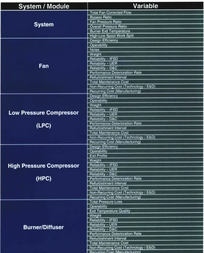
4.3.3 System Variables at the Module Level
Due to the modular construction of Pratt & Whitney engines, many of the system requirements described in the previous section are achieved by
specifying levels of system variables at the module level. In other words, many system requirements are achieved by summing the contributions from each major engine module. For example, one system requirement that is the sum of the module contributions is that of engine weight.
Not all system requirements are merely the cumulative total of all module contributions, as in the case of TSFC. From the earlier example illustrated in Figure 4.3, it was shown that TSFC is a system requirement that is influenced by the design efficiencies of the various engine modules including the fan, LPC, HPC, HPT and LPT. In reality, the efficiencies of some modules have a greater impact on TSFC than others. For example, a one percent change in HPT
efficiency has a greater impact on TSFC than does a one percent change in LPC efficiency. These non-linear effects are captured in the QFD mappings.
Listed below in Table 4.4 are the system variables associated with each of the major engine modules, as well as a set of high level system variables that may span across more than one module. These high level system variables are commonly used in turbomachinery design. A detailed description of their use and relevance may be found in the literature [Cohen et al., 1987; Dixon, 1978].