HAL Id: hal-02114562
https://hal.archives-ouvertes.fr/hal-02114562
Submitted on 29 Apr 2019
HAL is a multi-disciplinary open access
archive for the deposit and dissemination of
sci-entific research documents, whether they are
pub-lished or not. The documents may come from
teaching and research institutions in France or
abroad, or from public or private research centers.
L’archive ouverte pluridisciplinaire HAL, est
destinée au dépôt et à la diffusion de documents
scientifiques de niveau recherche, publiés ou non,
émanant des établissements d’enseignement et de
recherche français ou étrangers, des laboratoires
publics ou privés.
Dipole Antenna Printed on Paper Substrate for WLAN
Applications
D. Lo Hine Tong, Ph Minard, Christian Person, J Coupez, P. Borel, D. Izoard
To cite this version:
D. Lo Hine Tong, Ph Minard, Christian Person, J Coupez, P. Borel, et al.. Dipole Antenna Printed
on Paper Substrate for WLAN Applications. EuRAD 2018 : 15th European Radar Conference, Sep
2018, Madrid, Spain. pp.457-460, �10.23919/EuRAD.2018.8546513�. �hal-02114562�
Dipole Antenna Printed on Paper Substrate for
WLAN Applications
D. Lo Hine Tong
#, Ph. Minard
#, Ch. Person
*, J.Ph. Coupez
*, P. Borel
§, D. Izoard
§ #Technicolor Connected Home, Rennes, France*LabSTICC, IMT Atlantique, Brest, France §Centre Technique du Papier, Grenoble, France
Abstract—The design of a dipole antenna printed on a paper
substrate is presented in this paper. The antenna which integrates a compact balun is devoted for dual-band 2.4/5 GHz WLAN applications. The antenna is based on a double-side printed multilayer paper substrate and is fed with a coaxial cable for the testing. The simulated results of the whole structure are also presented in detail and compared with the measured performances.
Keywords—MIMO antenna; dipole antenna; paper substrate; balun.
I. INTRODUCTION
The constant demand of higher and higher throughput requires new generation of home networking devices such as Internet gateways and routers to integrate more and more antennas with up to 8*8 MIMO schemes for instance. This calls to ever figure out innovating and low-cost solutions when consumer mass-market is addressed. So far, FR4 substrate is mostly used for the design of the antennas but, with the numerous promising results published in the recent years, paper substrate printing can also be an interesting alternative cost-effective solution [3-7].
Using this technology, we designed a dipole antenna for WLAN dual band applications, operating in the [2.4-2.5] GHz and [5.15-5.85] GHz bands of the IEEE.802.11.b/g/a/n/ac standard. This paper describes first the proposed novel concept of dipole antenna that integrates a balun, then the design of the dual-band antenna printed on paper substrate is discussed deeply in section III, showing the simulated and measured results. In the last section some perspectives of this work are given.
II. DIPOLE ANTENNA WITH INTEGRATED BALUN
A. Concept with via-hole for feeding
This study is based on an original concept of dipole that integrates a balun [1]. Compared to common approach where balun circuit is cascaded in series with the antenna [2], in this novel approach the balun is integrated in one of the resonating element of the dipole, resulting in a much more compact design. Fig.1 illustrates an example of a dual-band antenna designed according to this principle and meant for WLAN applications. The design comprises two cascaded dipoles, with
A1&A2 resonating in the lower frequency band (2.4GHz) and B1&B2 resonating in the higher frequency band (5GHz). The antenna is fed through a modified Marchand balun formed by a microstrip to radial slot transition with the slot placed in one arm of the higher band dipole (B2). In this first mode of realization the feeding microstrip line is terminated by a via hole connecting this line to the radiating elements printed on the bottom layer.
Fig. 1. Original dual-band dipole antenna including a balun.
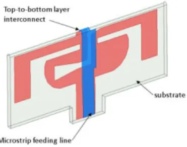
B. Concept with direct feeding
In this second mode of realization (Fig.2), which aims to get rid of the via-hole in order to reduce fabrication costs, the microstrip feeding line is extended to the upper side of the dipoles and interconnected to them by a U-shape transmission line. In practical, this design can be realized by using very common metal stamping process, where the feeding line and the radiating elements are stamped in a single metal plate and folded at 180° to form the suitable antenna design. In the following section it is described how the antenna can be realized by using printed paper substrate.
III. DIPOLE ANTENNA USING PAPER SUBSTRATE
A. Description
The proposed design of the dual-band dipole antenna is depicted in Fig.3 and Fig.4.
- First, the raw substrate used is based on the 200um-thick E4D paper (dielectric constant Dk=2.54, loss tangent Df=0.05 @6GHz), and the antenna patterns are printed by screen printing using a silver ink with a deposit thickness of 7um and a conductivity of 1.7MS/m. Performances of this technology were already demonstrated previously with the successful design of several kinds of antennas [3-5]. - Secondly, to ensure a proper rigidity of the paper-based
antenna a total thickness of 1mm is set and to meet this request several sheets of papers are stacked. To this purpose, the stack-up comprises 3* inner type#2 papers (without any patterns printed apart the grounding pad#3) on which is wrapped the type#1 paper where the antenna pattern with the feeding line are printed. With this assembling process, a total of 1mm thickness paper is obtained, with the feeding line printed on the top layer and the radiating elements on the bottom side.
- And finally, since the antenna is meant to be tested with a micro-coaxial cable (diameter 1.37mm), pads are added at the input port to guarantee a correct grounding of the cable through the multilayer structure. The via-holes are laser-drilled and metallized with a conductive glue.
Fig. 3. Paper-based dipole antenna fed with a coaxial cable.
Fig. 4. Constituent parts of the multilayer paper-based antenna.
The geometrical parameters of the whole structure, including the coaxial cable, were optimized using the HFSSTM
simulation tool to accommodate the required performances in both WLAN frequency bands.
B. Fabrication
Fig. 5 shows the realized circuits before cutting, stacking and assembling; L-shape patterns were added to ease the cutting. One can see the antenna pattern printed on the first area (Type#1) of the paper and only the grounding pad printed on both sides of the second area (Type#2) of the paper.
Fig. 5. Realized dual-band printed antenna before assembling.
The figure below shows the full design of the dipole antenna with the feeding and testing coaxial cable. The cable is attached to the paper with the help a conductive glue. Indeed, since this is done by hand with thus assembling tolerances the performances can be affected, especially in the higher band as it is shown in the following section.
Fig. 6. The whole realized dual-band dipole antenna fed by a coaxial cable.
C. Antenna performances
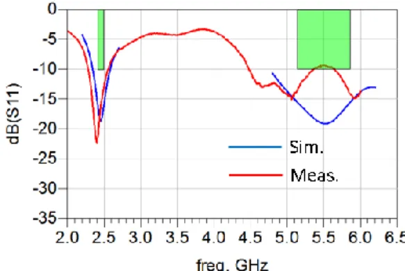
Fig.7 shows the measured coefficient reflection response compared to the simulated one. As can be noticed, there is a rather good correlation in the WLAN 2.4GHz band, with dB(S11) <-12dB. However, in the 5GHz band the measured S11 level is higher than expected; this is certainly due to the fabrication and assembling tolerances, in particular, as aforementioned, the discontinuities introduced at the transition between the coaxial cable and the microstrip line.
Fig. 7. Simulated and measured reflection coefficient of the dual-band antenna.
The radiated performances of the antenna were measured in near field with a StarLabTM testing system (Fig.8).
Fig. 8. The dipole antenna mesaured in near field with a compact StarLabTM
measurement tool.
From the gain and efficiency performances plotted in the figures below, we find again a quite good agreement between the simulation and the measurement results in the 2.4GHz: the measured peak gains are around 0.5-1dBi and the efficiencies close to 70%.
In the 5GHz band, the peak gains are more sensitive to measurement uncertainties since around 1dB difference with the simulated gains are observed. In the high band, the measured gains are around 2dBi and the efficiencies close to 65%.
Fig. 9. Simulated and measured peak gain and effciency of the dual-band antenna.
The 3D radiation patterns plotted in Fig. 10 and Fig.11, at respectively 2.45GHz and 5.5GHz, show that the antenna behaves like a dipole, exhibiting a null in the 0Y axis and a quite omnidirectional radiation in the ZX plan. One can also notice that the radiation pattern at 5.5GHz is a bit distorted by the presence of the 2.4GHz radiating arms.
Fig. 10. Measured 3D radiation pattern of dipole antenna at 2.45GHz.
Fig. 11. Measured 3D radiation pattern of dipole antenna at 5.5GHz.
IV. PERSPECTIVE
The achieved performances of the paper-based dipole antenna presented in this paper are comparable to the ones that can be obtained when using FR4 substrate as antenna carrier. Therefore, it could be an alternate low-cost solution for the development of home networking devices that requires many antennas to integrate. For instance, as illustrated in Fig.12, several dual-band antennas can be mounted directly onto a main board to address the needs of a 4*4 MIMO system. In that case, the antennas will be excited directly from the board without using coaxial cables.
Fig. 12. Example of application of the paper-based dipole antennas in an 4*4 dual-band MIMO system.
By using the same concept of dipole integrating a balun as presented here, a single band 5GHz WLAN antenna is also under development, with expected effective size of 22mm*10mm (Fig. 13), peak gains around 1dBi and efficiencies close to 70% (Fig.14).
Fig. 13. Paper-based 5GHz WLAN dipole antenna with integrated balun, with the simulated S11 response.
Fig. 14. Simulated peak gain and efficiency of the 5GHz WLAN dipole antenna.
V. CONCUSION
The concept of compact dipole antennas integrating a balun and printed on paper substrate has been presented. The prototype realized has demonstrated the high potentialities of the design and of the printing technology used, especially for future applications in the field of wireless systems that require a massive integration of low-cost antennas.
ACKNOWLEDGMENT
The authors acknowledge the French “Agence Nationale de la Recherche” for the financial support under the grant ANR-IG-CE26-0033-01 and the project name STICK’IT.
REFERENCES
[1] P. Minard, C. Rambault, D. Lo Hine Tong, A. Aubin “Dipole antenna with integrated balun”, US20160365640 Patent Application, 2016.
[2] P. Lindberg, E. O¨ jefors, Z. Barna, A. Thornell-Pers and A. Rydberg, “Dual wideband printed dipole antenna with integrated balun,” IET Microw. Antennas Propag., Vol. 1, No. 3, June 2007.
[3] D. Lo Hine Tong, A. Aysissi Manga, P. Minard, A.Dellatre, L. Crowther Alwyn, P. Borel "Comparative Study of WLAN Dual-Band Monopole Antennas Printed and Etched on Paper and PET Substrates", European Microwave Week, London, 2016.
[4] H. P. Phan, T. P. Vuong, P. Benech, P. Xavier, P. Borel and A. Delattre "Novel Ultra-Wideband “Robe” Antenna on High-Loss Paper Substrate", IEEE AP-S, San Diego, 2017.
[5] H. D. Nguyen, J. P. Coupez, V. Castel, C. Person, A. Delattre, L. Crowther-Alwyn, P. Borel, “RF characterization of flexible substrates for new conformable antenna systems”, 10th EUCAP 2016.
[6] S. Kim et al., “Inkjet-printed antennas, sensors and circuits on paper substrate”, IET Microwaves, Antennas & Propagation, Vol. 7, 2013. [7] V. Lakafosis et al., “Progress towards the first wireless sensor networks
consisting of inkjet-printed, paper-based RFID enabled sensor tags”, Proceedings of the IEEE 2010.