Composite information systems : a new concept in information systems
134
0
0
Texte intégral
(2)
(3) Center for Information Systems Research Massachusetts. Institute of. Alfred P Sloan School of. Technology. Management. 50 Memorial Drive Cambridge, Massachusetts, 02139 617 253-1000.
(4)
(5) COMPOSITE INFORMATION SYSTEMS. -. A NEW CONCEPT IN INFORMATION SYSTEMS. Chat-Yu Lam Stuart. E.. May. 1,. Madnick. 1978. CISR No. 35 Sloan WP No. 993-78. This report is based on Technical Report #3 prepared for the Rome Air Force Development Center under contract #F30602-77-C-0205.. Center for Information Systems Research Alfred P. Sloan School of Management Massachusetts Institute of Technology 50 Memorial Drive Cambridge, Massachusetts 02139.
(6)
(7) PREFACE. The Center for Information Systems Research. (CISR). is a. research center of the M.I.T. Sloan School of Management;. consists of. a. it. group of Management Information Systems. specialists, including faculty members, full-time research staff, and student research assistants.. The Center's general research. thrust is to devise better means for designing, generating and. maintaining application software, information systems and decision support systems.. Within the context of the research effort sponsored by the Rome Air Development Center under contract F30602-77-C-0205, CISR. proposed. to investigate the development of a software. programming environment for decision support systems using virtual machine technology as an integrating mechanism.. Research. issues to be studied include evaluating the potential utility of such. a. system for aiding Air Force SPO's in decision-making and. formulating methods for providing automatic interfaces between virtual machines within this environment.. In. Technical Report No.. 1,. interfacing virtual machines.. we studied various strategies for. Technical Report No.. 2. examines. specific decision support system in some detail, that makes use of some of the strategies for interfacing virtual machines.. this report, we generalize the approach of information system. architecture that makes use of existing, often incompatible. n H i^oH-. In. a.
(8)
(9) programs and databases.. We call such information systems. Composite Information Systems,. We shall discuss. a. structural. model of Composite Information Systems, and use this model to study several existing information systems that make use of the. Composite Information System approach in varying degrees..
(10)
(11) Abstract. As the problems confronting organizations and our society. become increasingly complex, it has been necessary to find more. effective software systems to aid in policy analysis and decision-making.. Decision Support Systems are information. systems developed for such needs.. While the number of software^. systems are increasing rapidly, quite often they are incompatible with one another.. It. is desirable to provide a facility whereby. existing software systems can be brought together rapidly to support decisions.. This approach of integrating existing, often. incompatible software systems is called the Composite Information System approach, and the resulting information system is called. Composite Information System (CIS). .. Research in CIS will provide better understanding of the. technology for more effective CIS. first step in that direction.. In this report,. we take a. Concepts for studying CIS are. developed and applied to several existing information systems that exhibit some characteristics of the CIS approach.. a.
(12)
(13) 16 2 4 3 7 8. Table of Contents. I. Motivation for Composite Information Systems Example Application. I.l 1. II. III. .. 6. Example Solution. 2. Concepts for studying CIS. 7. II. "^ 1. 11.. A structural model of CIS. H. 11.. Strategies for component integration. 27. Study of specific systems that exhibit the CIS approach III.l. Type. III.. Type II. 2. I. Cross-tool-different-data-format. -. Type III. 111.. Cross-tool-different-data-system. -. Type IV. 5. Type V. Cross-execution-environment-different-. -. 44. Cross-OS-different-data-format. -. 111.. Type VI. 111.. Type VII. 111.. Type VIII. 34. 39. data-system III.. 30. Cross-execution-environment-different-. -. data-format 111.. •'^0. Cross-OS-different-data-system. -. Cross-machine-different-data-format. -. Cross-machine-different-data-system. 50 50 53 54. IV. Conclusions. 58. V. References. 59.
(14)
(15) Composite Information systems I. Motivations for Composite Information Systems. As problems confronting organizations and our society become. increasingly complex, it has been necessary to find more. effective software systems to aid in policy analysis and decision-making.. This increased complexity and urgency is the. result of factors such as. :. (1). the scarcity and unreliability. of many essential natural resources, most notably energy 76a). an. ,. and. (Donovan. the subtle interdependence of many decisions where. (2). 'optimal' decision to resolve one problem may in fact,. precipitate worse problems in other areas (Forrester 75).. At the same time, the number of powerful problem-solving. software systems have increased rapidly. time, solving. a. large linear program was. For example, at one a. major programming. effort; today, a large number of general purpose LP packages are. available so that the user can concentrate on problem-solving rather than programming.. Large and powerful econometric. modelling facilities and models are available and frequently used for policy analysis; statistical and analytical packages are. widely used in Management Science; database systems have become. essential means of handling the complex data requirements of organizations; and many other major software systems are. available and in common use.. Unfortunately, these problem-solving software systems are. often not compatible with one another.. The developers of these.
(16)
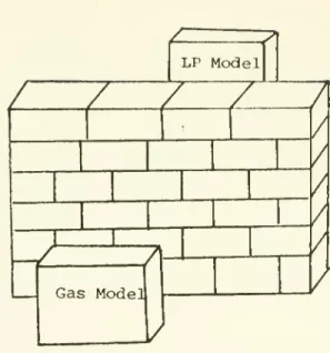
(17) systems seldom work in close coordination.. Furthermore, it is. not possible to anticipate and to allow for the different ways the software systems will be used in the future.. faced with a difficult situation.. Thus we are. On the one hand, rnont. non-trivial problems require powerful software systems to aid the. problem solution, on the other hand, existing systems are often incompatible with one another, and it is highly unlikely that an unified development of these systems will emerge in the future.. Efforts to integrate these separate systems into. a. single. high-level process have been difficult to accomplish. overhead,. The. inconvenience, inefficiencies, and complexities. associated with repeated crossing of system and data boundaries have been prohibitive.. I.l. Example Application. Let us illustrate some of these concepts using a hypothetical case.. The Ozo Gas Company is. in the Mid-West.. It. a. major distributor of natural gas. acts as an intermediary between the gas. suppliers and the consumer and its major profit comes from. efficient distribution of natural gas. a. The company has developed. LP model of the, gas distribution process and has been using it. as basis for policy making.. Basically the LP model takes. projected supply and demand information and generates an optimal. distribution schedule as well as the projected profit associated with the schedule.. This is illustrated in Figure I.l.. well until the 1973 Oil Embargo.. All was. Since then government has been.
(18)
(19)
(20)
(21) considering new natural gas policies.. (There has been. price. a. ceiling on domestic natural gas and government is considering. alternative policies to encourage natural gas production). Management is anxious to find out how the various new policies would affect its profit from the distribution process. learned that experts in Cambridge have built gas supply and demand model. (e.g.. a. They. powerful national. the MacAvoy-Pindyck gas model. (MacAvoy and Pindyck 75)) which can be used to analyze effects of. various gas policies on expected demand, expected supply and. prices (Figure 1.2).. Ozo gas is particularly interested in using. the output from the national gas model as input to its LP model, so that by varying the parameters input to the gas model,. corresponding to the various new gas policies, the effects of these policies on the gas distribution process, e.g. optimal. distribution schedules and profit levels, can be determined. This ideal situation is depicted in Figure 1.3.. Unfortunately, the LP model and the gas model are not. compatible with each other. uses OS/360 file system.. The LP model was coded in APL and. The gas model is expressed in TROLL. (NBER 75b), a powerful econometric modelling subsystem designed to operate under the VM/370 operating system using. system.. its own file. This situation is illustrated in Figure 1.4.. It. seems. that to use the two models jointly, Ozo Gas would have to either. reconstruct one of the models to operate under the same operating. environment as the other, or manually perform the interfacing.
(22)
(23) 10. LP Model. z / / / / /. 7 Gas Mode]. Figure 1.4. Incompatible Models. LP Model. Figtire 1.5. Result of effective interface between incompatible models.
(24)
(25) .. 11. across the two system boundaries.. Both approaches are costly and. time consuming for such one-time decisions.. desirable to Ozo Gas is. a. What would seem. facility that can incorporate these two. models easily and rapidly so that the two models can be jointly usable.. That is,. a. facility that breaks the wall between the two. models with minimal changes to either model. (Figure 1.5).. Similar problems as the Ozo Gas Company case are facing many. organizations and our society today.. 1.2. Example Solution. The Generalized Management Information System (GMIS) and Jacoby 75). at MIT for example,. (Donovan. uses virtual machines to host. many powerful, though possibly incompatible application software and database systems in support of the New England Energy. Management Information System (NEEMIS) Project (Donovan 76b) The purpose of the project was to develop an information system for the New England Regional Commission to assist policy makers in managing the problems brought on by the energy crisis-. Better. information was needed to analyze methods to conserve fuel and to assess the impact of tariffs and prices on different industrial sectors and states within the region.. Support was also required. for many other studies, such as the analysis of the merits of. refineries in the region, and monitoring the impact of various. conservation measures.. The computer-based GMIS/NEEMIS system was. developed to allow researchers to respond in. a. timely and. effective way, to demands for information analysis that has not.
(26)
(27) 12. been previously anticipated.. The GMIS/NEEMIS system has been classified as an ad-hoc. Decision Support System (DSS). (Donovan and Madnick 76b). to. differentiate it from another type of DSS called institutional DSS.. An institutional DSS supports a recurring decision of a. particular type, for example, the decision of to buy or sell bonds. For example, decisions on the. wider range of decision types.. allocation of energy resources is. a. decision type within. logical group of energy related decisions. (1). portfolio manager. An ad-hoc DSS must address a. (Gerrity 71).. of an ad-hoc DSS are that. a. a. Major characteristics. the decision and the data needs for. its analysis are not known long. in advance,. time pressure for information, and. (3). (2). there is great. the perception of the. decision as well as the needs for its analysis often change as more information is made available to the decision-maker. there is. Thus. need for an approach that allows existing, often. a. incompatible, problem-solving software systems to be rapidly. integrated at low fixed inital cost to solve problems of great. complexity.. One approach to meet these needs is to provide. a. facility that can host these systems and incorporate new systems. easily and quickly. systems. a. We call such an facility and its software. Composite Information System (CIS) and this approach of. information system development the CIS approach.. In. this report,. we develop concepts useful for studying CIS and examine several. existing system development efforts that made use of the CIS. approach in varying degrees..
(28)
(29) .. 13. II. Concepts for studying CIS. A CIS is a computer facility to host a variety of compononts (e.g. database systems, models, and application programs). th.it. may have been developed by different people, often for diffcrtMil purposes.. These components often operate in different operating. environments and use very different types of databases.. Thur,,. various types of incompatibilities among these components may To make these components jointly usable,. arise.. the problems. associated with crossing system and data boundaries have to be solved.. An effective CIS provides the capabilities to facilitate. component integration.. Various strategies can be used to solve. the problems associated with crossing system and data boundaries.. Hence, an effective CIS provides a computing environment to. facilitate the joint usage of an assortment of components so that the user of these components does not have to be concerned with. computer problems, but to concentrate on solving his(her). problems. In. Section II.. components in. 1,. a CIS,. we clarify some concepts regarding types of. and discuss several types of data and system. incompatibilities among these components.. These characteristics. of a CIS constitute a structural model of the CIS. II. 2,. several strategies that may be used in. a. In. Section. CIS for resolving. incompatibilities among components are discussed..
(30)
(31) 14. II.. 1. A Structural Model of CIS. A structural model of a CIS describes the various compon(^nhs in the CIS with their associated operating environments,. and the. various incompatibil ites among these components across system and data boundaries.. In this section, we. components in. a. environments,. (2). and. (4). CIS.. These are. tools,. (3). database systems.. :. (1). shall discuss four types of. operating system execution. special execution environments,. The various types of system and data. boundaries that may exist among these components are then d. iscussed.. II. 1.1. Components in. a. CIS. The basic components in a CIS are the tools. (e.g.. application. programs, models, and analysis routines), and the operating system execution environments they operate in.. To facilitate construction and operation of tools for special. applications (e.g. econometric modelling), special execution. environments have been developed.. A special execution. environment provides high-level primitives to support. construction of new tools and operation of existing tools for particular application orientation.. Another type of CIS components, database systems, have been. developed to facilitate management of complex data structures. a.
(32)
(33) .. 15. used by tools.. These four types of CIS components are discussed. below.. (1). Execution environments. -. Operating Systems (OS). An operating system supervisor. (OSS). manages the resources in. a. computer system.. a. program can invoke to utilize the computer resources, e.g. to. read. a. The OSS provides macros and subroutines thah. file on a disk.. The OSS also provides special utility. programs that an user can invoke to perform various maintenance functions, e.g. allocate space for. a. file, copy a file, etc.. user communicates his/her requests for service to the OSS via. control language. for user requests.. There is. a. to. For example,. run program X.. a. component of the OSS that listens in the. case of. a. non-multiprogrammed OSS, the listener may pick up a user. An. a. The OSS initiates program. request from X. and passes. control of the central processor unit (CPU) to program. X.. When. program X finishes its processing, control of the CPU is returned to OSS and the listener. requests.. is. reinitiated to wait for more user. We often refer to this OSS loop as a listening loop.. From the point of view of the user within the OSS listening loop, the OSS,. its utilities, and the computer resources. collectively provide him/her an execution environment to construct new programs, run existing programs and perform. maintenance functions provided by the OSS.. We refer to this type. of execution environment loosely as an operating system. (OS).
(34)
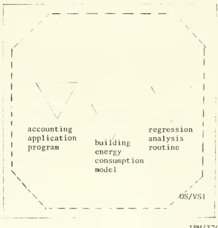
(35) 16. Tools. (2). A tool. is a. program that represents. closed-ended computation.. well-defined,. a. A tool usually receives control from a. supervisor of the execution environment that the tool is in.. performs its computation and may carry on. a. It. dialog with the user. during its computation, typically to obtain some input-. At. the. end of the computation, the tool returns control to the execution. environment supervisor.. A tool may be an analysis routine, or. it may be a model,. consumption of e.g.. a. e.g. a regression routine;. e.g. a simulation model of the energy. building; or it may be an application program,. an accounting program.. Figure II.. 1. illustrates several. tools operating under the OS/VSl multiporgramming operating system.. (3). Special execution environments. There is another class of programs that behave quite. differently from tools.. We refer to this class of programs as. special execution environments.. A program of this type receives. control from the execution environment supervisor, but does not. immediately return control to the supervisor.. In fact,. the. program proceeds to set up its own listening loop and in effect traps the user in another execution environment.. In general,. the. user communicates with such a special execution environment via. a.
(36)
(37) 17. \. /. \^ i. /. I. accounting application program. I. \. \'. building energy consumption model. regression analysis routine. J. \ \. ^S/VSl. IBM/370. Figure II.. 1. Tools operating under the OS/VSl operating system.
(38)
(39) .. 18. command language (e.g., an APL interpreter).. The user is able to. construct new tools, run existing tools and may be able to perform some maintenance functions within the special execution environment.. Although eventually control is returned to the. execution environment supervisor, by explicit user request, the computation represented by this program is ill-defined, and open-ended. We have identified two major subclassses of special execution. environments.. These are the generalized language interpreters. and the special purpose language processors.. (a). Generalized language interpreters. Generalized language interpreters include all the interpretive programming languages, e.g. APL, BASIC, and so forth.. A. generalized language interpreter usually is directly under an operating system.. The listener of the execution environment is. the language interpreter.. Under this execution environment, the. user is able to construct new tools interactively, run existing tools, and to perform some maintenance functions.. maintenance functions are often the host operating system.. a. These. subset of those available from. There is considerable variations in. the scope of these functions across different host operating For example, under the Cambridge Monitor System. systems. (IBM 76). ,. (CMS). an APL user can invoke most of the CMS commands via the. APL shared-variable facility, however, under OS/VSl, the APL user.
(40)
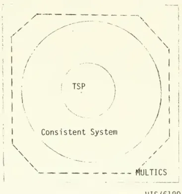
(41) .. 19. has very limited access to OS/VSl system maintenance functions.. (b). Special language processors. Specialized language systems have been developed to reduce user programming efforts and to better suit the particular. application interests of the users.. For example,. special systems. have been designed for construction of simulation models, for. construction of econometric models and for data analysis, and so forth.. Many of these systems behave like. enviornment we discussed above.. a. special execution. Furthermore, due to the special. application orientation of most of these systems, they often have their own special file systems particularly suitable for their. applications.. Thus, the maintenance functions available to the. user in such a special execution environment may be quite. different from those available to the user if he/she were in the host execution environment.. Notice also that an execution. environment may reside on another execution environment which may reside on yet another execution environment, and so forth. example. Figure II.. 2. Time Series Processor. illustrates that (TSP). a. For. modified version of the. runs as a special language processor. under the Consistent System (Cambridge Project 74c), which is. special execution environment for social science research that runs under the MULTICS operating system on a Honeywell 6180. computer. a.
(42)
(43) 20. /. \. \ \. if. ;. \ TSP. \. Consistent System. \. \. \ MULTICS HIS/6180. Figure II. 2. Illustration of execution environments.
(44)
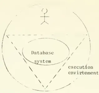
(45) 21. (4). Database systems. A database system (DBS) consists of two basic components:. databases and. a. the. program that manages these databases and provides. data access interface(s). for the user of the databases.. The. databases may be constructed using very complex data structuring techniques, e.g. indexing, chaining, etc, or they may be. constructed using very simple data structuring techniques, e.g. sequential file organizations.. The data access interface, also. referred to as the data manipulation language (DML) could be. a. set of subroutines usable only via program calls, or it may be. language interpreter that. a. user can use interactively.. a. In. either case, the nature of the language supported may be either low level operations such as GETNEXT RECORD, or high-level. operations such as PRINT ALL EMPLOYEE WITH SALARY OVER 35000. From the point of view of the user, a DBS consists of. a. collection of logical databases, and the data access language(s) to manipulate thses databases.. DBS via. The user may interact with the. procedural program or without using such. a. both, depending on which mode(s). a. program, or. of operation that the DBS. supports.. In some cases a DBS may be used as a. tool.. For example, a. specific application program and the DBS software may be linked into one load module and executed as. ordinary tool. a. DBS is. a. a. giant program, like an. This situation is depicted in Figure II.. 3.. Since. very expensive resource and is often used to support.
(46)
(47) 22. Q /\. \ \(. Database. //. \N~.system. ,-'.. \. /. / execution envirbnment. /. \. \. s. \. / N /. Figure. 1. Database system used as a tool. 1. 3. ^. (. r). execution. v. \. enviroitiment. /'. \. \. Database system. Figure. I. I. 4. Database system servicing multiple execution environments. N\ ,/-. Figure II. 5. /. Database system used as an execution environment.
(48)
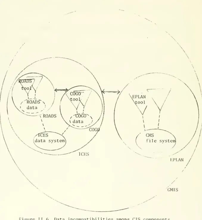
(49) 23. all the data needs of an information system, a frequently used. mode of DBS operation is to execute the DBS independent of other. application programs.. The DBS executes like an execution. environment servicing database requests from various users. situation is depicted in Figure II.. 4.. This. Yet another mode of. operation for the DBS is possible for those DBSs that have interactive language support. interpreter may execute as. a. The DBS with its language. database execution environment.. This situation is depicted in Figure II.. II. 1.2. 5.. Incompatibil ites among CIS components. Two basic types of incompatibil ites may exist between. components in. a. CIS:. (1). operating environments,. the components may operate on different. (2). the components may use different data. format or data systems.. (1). Data differences among components. Two components may use the same type of file system, but each. may encode the data differently, thus making it difficult for the two components to communicate.. Two components may use entirely. different file systems, making the task of integrating these two. components more difficult.. For example. Figure II.. 6. illustrates. various data incompatibilities that may exist among components in a. CIS.. In Figure. II. 6,. circles represent execution environments,. triangles represent tools, solid ovals represent data systems..
(50)
(51) 24. \. GMIS. Figure II. 6. Data incompatibilities among CIS components (operating environment differences not shown).
(52)
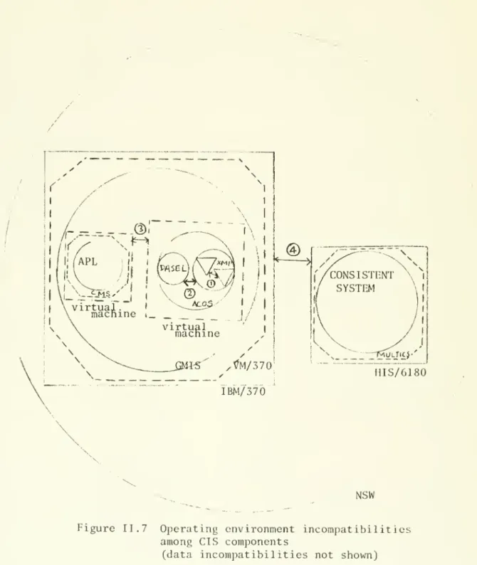
(53) :. 25. and dotted ovals represent local data with the same format.. Figure II.. 6. illustrates the following (The ICES, EPLAN, and GMIS. systems are explained in later sections) (1). Tools within the ROADS execution environment use the same. data format, (2). Tools within ROADS use different data format than tools in. the COGO execution environment, (3). Both COGO and ROADS use the same basic ICES file system,. (4). EPLAN uses. (5). ICES provides interfaces to resolve data format differences. a. different basic file system than ICES,. among COGO and ROADS, (6). GMIS provides interfaces to resolve data system differences. between EPLAN and ICES.. (2). Operating environment differences. Operating environment incompatibilities among components may be due to differences in execution environments, operating. systems, or the host machine.. Figure II.. 7. illustrates the. various types of operating environment differences among CIS components..
(54)
(55) 26. HIS/6180 IBM/ 370. NSW Figure II.. 7. Operating environment incompatibilities among CIS components (data incompatibilities not shown).
(56)
(57) 27 In. Figure II.. 7,. solid squares represent real machines, dotted. squares represent virtual machines, and dotted octagons represent. operating systems.. Figure II.. 7. illustrates the following typos. of system boundaries: (1). Different tools in the same execution environment. -. to. interface between two such tools would entail crossing tool boundaries, e.g. different tools in the same XMP execution. environment. (2). Different execution environments in the same host operating. environment. -. interfacing two such execution environments. requires crossing execution environment boundaries, e.g.. different execution environments in the same ACOS system.. Different operating system under the same virtual machine. (3). -. system. interfacing two such OS requires crossing virtual. machine boundaries and operating system boundaries, e.g.. different virtual machines in the GMIS system. Different real machines. (4). -. interfacing two such machines. requires crossing real machine boundaries as well as operating system boundaries, e.g. different machines in the NSW system.. Strategies for component integration. II.. 2. In. this section, we discuss several broad strategies that may. be used for. integrating CIS components, then we examine types of. databases that may be used to support these strategies.. There. are two basic types of strategies for component integration,. those used for resolving data differences and those used for.
(58)
(59) 28. resolving system differences.. (1). Strategies for resolving data differences. A frequently used strategy for resolving data differonccs. among CIS components is to make use of. a. common data system.. Data translation routines are provided by the CIS to move data. from. a. component to the common data system, and from the common. data system to. a. component.. Thus the common data system,. in. effect, acts as an intermediary among components that use. different data formats or data systems.. An alternative strategy for resolving data differences among. CIS components is to make use of an interface routine for. pair. a. The number of interface routines required grows. of components.. as the squared of the number of components in the system.. For. systems with small numbers of components, this strategy may be. very effective since each interface routine is tailored for. particular component pair. exclusive, and. (2). a. a. These two strategies are not mutually. CIS may make use of both strategies.. Strategies for resolving system differences. The basic problems here are communications and data transfer. across system boundaries.. To resolve these problems, three. complementary strategies may be used: or develop new inter-process or. (1). make use of existing,. inter-machine communications.
(60)
(61) .. 29. protocol,. (2). make use of. these activities,. (3). a. overseer process for coordinating. make use of special routines to. encapsulate components, so as to trap the I/O issued by the components.. A study of these strategies in a virtual machino. environment is reported in (Lam and Madnick 78a). We found that three types of auxiliary information may be used to support component integration in a CIS.. First, static. information about components in the CIS, e.g. catalog of the common file system, and catalog of the command syntax for certain components. e.g.. Second, operating status of components in the CIS,. current status of components being used.. This type of. information is used by the CIS overseer process in coordinating. activities in the CIS. components, e.g.. requirements.. Third, detail information about. their I/O characteristics and data. These information can be used for constructing. automatic interfaces among components..
(62)
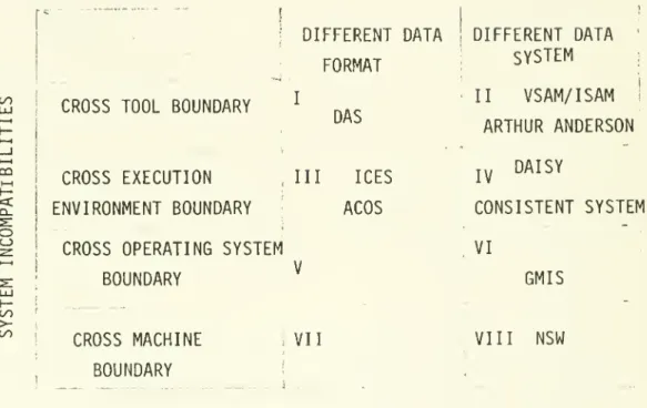
(63) 30. III. Study of specific systems that exhibit the CIS approach. A CIS provides a facility for joint usage of existing, often. incompatible components by using various strategies and. mechanisms to resolve the possible data/system incompatibilities A CIS approach system development effort. among components.. one in which some characteristics of. a. is. CIS are present.. A literature study has been conducted to identify information. systems that exhibit the CIS approach.. Eight generic types of. CIS were identified using a taxonomy of CIS according to their. structural characteristics.. Figure III.l categorizes CIS along. two dimensions of their structural characteristics. incompatibilities among CIS components and incompatibilities among CIS components.. (2). :. (1). data. system. The nine example. CIS-type systems that we identified in the literature fall into six of the eight generic types, as illustrated in Figure III.l.. subsections below, we shall briefly discuss. In each of the. each generic type of CIS and the sample systems within it.. III.l. Type. I. -. Cross-tool-different-data-format. The problem of different tools using different data formats. exists even when these tools operate under the same operating environment.. This is one reason for the development of special. execution environments whereby tools that are often used for an.
(64)
(65) 31. DATA INCOMl'Al'TBILrni-S. 1. DIFFERENT DATA I. FORMAT CO. CO. < o. II. I. CROSS TOOL BOUNDARY. DAS. CROSS EXECUTION. III. ENVIRONMENT BOUNDARY. ICES. ACOS. CROSS OPERATING SYSTEM. DIFFERENT DATA SYSTEM. ARTHUR ANDERSON IV. DAISY. CONSISTENT SYSTEM VI. ;. GMIS. ^. BOUNDARY. VSAM/ISAM. LlI. tC/J >to. CROSS MACHINE. BOUNDARY. Figure III.l. VII. VIII. NSW. !. Categorization of sample CIS-type systems.
(66)
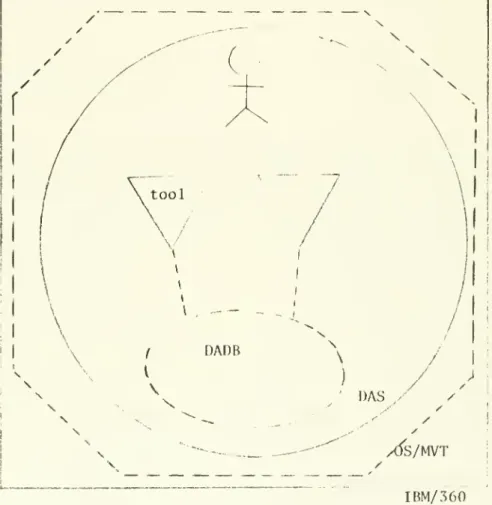
(67) .. 32. application area are brought under. consistent operating. a. environment using compatible data formats.. We shall briefly. describe one such system, called Data Analysis System (DAS) (Levitt et. al.. 74). The Data Analysis System (DAS) was developed at the RAND. Corporation to provide. a. flexible data analysis system with. advanced graphic displays.. This effort was initiated to meet the. need for flexible statistical tools required in the process of. solving complex statistical problems.. The system was seen as a. solution to the difficulties of using current statistical packages, since most current 'canned'. statistical analysis. programs are very rigid in their data requirements, thus place. a. burden on the user to repeatedly restructuring data when there is a. need to use several of these programs in succession.. Figure III. 1.1 illustrates the structure of DAS.. Data. analysis programs in DAS include FORTRAN programs developed in-house, as well as subroutines acquired from the BIOMED. library.. These routines all operate under the same OS/MVT. operating system. Data Base. (DADE). A common DAS database, called Data Analysis is used by all the. DADB is organized into sets.. programs in DAS.. Data in the. A set is a table of values.. Operations on sets include editing, subsetting, intersection, union, etc.. DAS was implemented on an OS/MVT system on an. IBM/360 machine.. A graphic subsystem was used to make on-line. access to DAS possible..
(68)
(69) 33. Figure. 1 1. 1.. 1.1. DAS.
(70)
(71) 34. III.. 2. Type II. -. Cross-tool-different-data-system. Under the same operating environment, tools may use different. data systems.. For example,. it. is quite common that two different. database systems be operating under the same operating system. Interfacing tools that use different data systems involves. crossing these data system boundaries.. Let us examine two such. cases.. (1). ISAM/VSAM interface. The IBM Index Sequential Access Method used.. (ISAM). has been widely. ISAM organizes files in physical cylinders.. One track on. the cylinder is reserved for storing the indices, one for each. data track on the cylinder.. There is. a. separate area to store. higher levels of indices for these track indices.. Data on a. track is organized in sequence with respect to a key.. entry correponding to that track.. a. data track indicates the highest key on. This arrangement of data in the file allows an user. random access to. a. record based on. in key sequence efficiently. (1). The index. a. key and access the records. Two major problems with ISAM are:. when no more records can fit on. a. track the overflow records. are stored in an overflow area and chained in key sequence, thus. deteriorates access time, and. (2). there is no dynamic space. reclaimation for deleted records.. The Virtual Storage Access Method. (VSAM). was developed by IBM.
(72)
(73) 2. 35. as an improvement over ISAM.. VSAM has similar overall logical. file organization as ISAM but organizes the file in logical. cylinders called CONTROL-AREAs and logical tracks called. CONTROL-INTERVALS.. By allowing CONTROL-AREA and CONTROL-INTERVAL. splitting when they become full, VSAM avoids using any overflow area.. The space within a CONTROL-INTERVAL is managed dynamically. so that the space occupied by deleted record can be reclaimed.. An interface program was developed by IBM so that. organizations with existing programs that use ISAM can continue to operate without modification, when the ISAM dataset is. converted into. a. VSAM dataset.. Figure III. 2.1 illustrates this. situation before the interface is used and Figure III.. 2.. illustrates the situation after the interface is used. Presumably new programs would be written directly for VSAM bypassing the ISAM/VSAM interface.. This is one of the examples of. a. more general problem.. A. major investment is made in the application programs that are. based on. a. particular database system or file system.. If a major. improvement over these file system and database system becomes available, to ease the transition to the new technology, an. interface is developed so that existing programs can still. operate on the old data system while actually the data is managed by the new data system.. (2). Arthur Anderson's Data Dictionary.
(74)
(75) 36. /. \. r. \ \. /. \. I. ISAM. data system. \. !. \ \. / OS/VSl. /. l_.. IBM/370. Figure II I. 2.1. Before using interface. n. / '^. \. 7. tool. I. /. \. /. / I. I. ISAM/VSAM interface. I. i. '. I. I. VSAM data system. \. /. / \. /. \ OS/VSl. L. IBM/370. Figure. I. II. 2. 2. After using interface.
(76)
(77) 37. Arthur Anderson. &. Co., a major accounting firm, developed. several accounting packages for its clients.. Since these. cliont-r,. often use different database systems, the firm chose to dovolop. n. general interface for the accounting packages so that they can bo used with any of the clients' database systems, e.g. ISAM or VSAM.. IMS,. IDMS,. The approach used by this firm is to make use of. data dictionary (Arthur Anderson. &. Co.. 76). a. to store the. application program's view of data as well as the definition of data on these various database systems.. The program's view of. data and the particular database system that the data is actually stored determine how data are to be accessed, to access the data.. For each installation,. i.e.. the procedure. the information in. the data dictionary about the application program is used to. create. a. database I/O interface program for that application. program for the particular database system used by that installation.. This interface then acts as a coordinator to call. other generalized interface routines such as translation routines that map the standard data access calls used by the application. program to the actual calls to the particular database system, and the various data translation routines.. Figure III.. 2. 4. Figure III.. 2. 3. and. illustrate the use of such interfaces in two. different installations.. This is an example of. a. general class of problems.. There is. much research attention in finding an unified data model for all the existing data models.. Data operations based on this unified. data model can then be mapped into data operations based on any.
(78)
(79) .. 38. \. \. N. "stamlarcl. "j. interface. (. \. (. (IMS version). I. --L—. .... \ IMS. data system. /. \. / \ ^. /. —. OS/V-Sl. TBM/370. Figure III.. 2. 3. Installation. i. \ /. /. \. X. \. \. standard interface {^TOTAL versj_ort) '. I. I. |. 1. \ TOTAL data system. \. /. K. / __. ^s/ysi /. IBM/ 370. Figure III. 2. 4. Installation. j. i.
(80)
(81) 39. existing or future data models.. Thus application programs. developed using this data model can be buffered against the. heterogeneity of database systems.. Such general solutions are. still under intensive investigation.. III.. 3. Type III. Cross-execution-environment-d i f fcrent-. -. data-format. Two execution environments in the same operating environment. may use the same basic data system, but due to their different. application focuses, may encode data differently.. When these two. execution environments need to exchange data, these data format. differences between the two have to be resolved.. (1). ICES. The Integrated Civil Engineering System (ICES). designed to provide. a. (Roos 67). was. convenient and systematic facility for. development of high-level problem-oriented subsystems to aid civil engineers in problem-solving.. The system was designed so. that independently developed subsystems can be easily. incorporated into ICES and be used in an integrated and. coordinated manner.. ICES is a special execution environment.. illustrates the structure of ICES.. Figure III. 3.1. Figure III. 3.1 illustrates. two execution environments in ICES, A Roads Design System.
(82)
(83) 40. /. /. /. /. /. / \. \. \. \. /. /. T. ^ /\. /. \. \'^r.t.\^ i. /. l\s. H \. /. '. ^. ^. -^-. ,1. u^ \. y. ^^. ROA OADS. \. COGO V. \ \ \. \. I. /. \. \. \. ICES. /'' I. data system. ;. \ \. ICES. \. /. / OS/MVT. IBM/ 3 60^. Figure. 1 1. 1.. 3.1. ICES. 1 '.
(84)
(85) 41. (ROADS), and a Coordinate Geometry System (COGO). .. Both execution. environments use the same basic ICES file system but each uses different data formats.. For example, a point in COGO may be. represented quite differently from the representation of the same point in ROADS. in a. Data from one subsystem may be saved to be used. subsequent subsystem.. ICES automatically performs the data. translation and data transfer, when the user goes from one. execution environment to another execution environment.. The. common ICES file system manages dynamic arrays, relational data Access to any of these. structures and the standard IBM OS files.. files can be made via high level commands imbeded in programs. As indicated in Figure III. 3.1 ICES runs under an OS/360. operating system on an IBM/370 computer.. ICE Excutive. (ICEX). is the. ICES overseer process that perform. much of the subsystem transition and coordination activities in There are two key types of information in the ICES system. ICES.. database. about. a. First, the command dictionary contains information. particular command, its syntax, its data characteristics,. and so forth, so that ICEX can automatically prepare the module. corresponding to the command for execution.. Second, When. a. subsystem is implemented, the ICES programmer specifies the. characteristics of the data structures required in the subsystem. This information is stored in the system dictionary.. The data. translator uses this information to create the corresponding new data structures in. a. new subsystem when. transfer to that subsystem.. a. user request data.
(86)
(87) .. 42. ACOS/ACOL. (2). The Application Control Operating System/Application Control. Language (ACOS/ACOL). (NBER 74). (NBER 75a). was developed by the. National Bureau of Economic Research (NBER). Inc... The system was. designed to host existing and future NBER developed tools.. These. tools include the Time-Shared Reactive On-line Laboratory (TROLL), which has been widely used for econometric and data. analysis. Figure III.. ACOS/ACOL.. System (XMP). 3. 2. These are the Experimental Mathematical Programming ,. and the Data Analysis and Statistical Experimental. Language (DASEL) system.. illustrates two execution environments in. XMP is an advanced mathematical programming. .. DASEL is. a. powerful high-level data analysis language. that operates on generalized arrays.. Both execution. environments, as well as other execution environments in ACOS/ACOL, use the same ACOS/ACOL file system.. This common file. system is structured much like the MULTICS hierarchical file system.. The execution environments may encode data very. different from one another.. For example, DASEL deals with. generalized arrays while XMP deals with special data files. convenient for mathematical programming.. As. illustrated in Figure III.. operating system for system.. a. 3. 2,. ACOS operates as an. virtual machine under the VM/370 operating. The VM/370 operating system runs on an IBM/370 computer..
(88)
(89) 43. \. ^\'. \. (. '. pArA. I. ./. X. /. ACQS. data system. yACQS \. ,. \. -. /. I. M. irtuai- mactrtne. /. V. VM/370 IBM/370. Figure IT I.. 3. 2. ACOS/ACOL.
(90)
(91) 44. Thus ACQS performs all the functions that an operating system. usually performs, such as handling I/O, storage management,. program initation and termination, and managing the associated. databases to support these functions. language for ACQS.. It. ACOL is the control. is a very high-level macro language Cor. specifying the sequences of operations to be performed For example, when a tool. is created,. a. l)y. ACQS.. programmer can use tho. ACOL facility to specify the syntax of the command that can be used to invoke the tool, the various I/O parameters associated. with running the tool, and the sequence of operations that ACOS. performs to initiate the tool. stored in. a. This information is processed and. database to be used by ACOS in responding to users'. requests.. III.. 4. Type IV. -. Cross-execution-environment-different-. data-system. Two execution environments in the same operating environment. may use different data systems.. Interfacing between these. execution environments involves crossing data system boundaries.. (1). The Consistent System. The Cambridge Project was a cooperative effort organized by. scientists at M.I.T. and Harvard University with the goal of making the computer more useful and usable by researchers in the basic and applied behavioral sciences, and in other sciences that.
(92)
(93) 45. have similar computing problems.. The project had two main goals:. first, to develop the necessary programs and computing tools; and. second, to combine these tools and others that may be developed. elsewhere into. a. consistent set of programs, models, and data.. The Consistent System (CS). is part of the efforts of the. Cambridge Project.. The Consistent System (CS). is a special execution environment.. Figure III. 4.1 illustrates three execution environments within CS.. These are the JANUS database system (Cambridge Project 74b),. the Time Series Processor. system (MP). (TSP). ,. and the Mathematical Programming. All three execution. (Cambridge Project 74a).. JANUS is an. environments use different data systems.. user-oriented database system that enables the user to manipulate data as logical entities and relationships among the entities TSP is. using a high-level query language.. a. modified version of. the popular batch TSP programs that use their own data system.. MP is developed for the CS and uses the CS file system.. The CS. file system is used as an intermediary among these different data. systems.. For example, a user may enter JANUS, perform some data. management functions on JANUS files, select specific results of interest and put them in. a CS. file, leave JANUS, go back to CS. listener level, enter TSP and issue. a. TSP command to get the CS. file created in JANUS for further analysis in TSP.. several major types of CS files.. These are the CHARACTER files,. the MN-arrays, and the GENERAL-arrays.. file description and. a. There are. data portion.. Each file consists of All programs in CS can. a.
(94)
(95) 46. / \. /. \. /. \. / /. \ \. /. Vc c U. '\. -7. MP \. \ iP^nU^. \. \. y. I. u >. \. P/-TA. /. RP'SE.. /. \. \. /. \ \. /. \. /. r'tOL'! I<-'J. ^l^/6lfi'(). Figure. 1 1 1.. 4.1. CONSISTENT SYSTEM. i. i.
(96)
(97) ,. 47. accept CS files as input and can output CS files.. The control of CS is mainly the task of the CS SUBSTRATE.. The. SUBSTRATE was designed to buffer CS from the host operating system so that the CS can be used in other operating systems, such as OS/360.. Thus CS maintains. a. large database similar to. those maintained by the operating system, e.g.. storage, files, and processes, etc. under the MULTICS operating system on. (2). status of. CS is currently implemented a. HIS/6180 computer.. DAISY. The Decision Aiding Information System (DAISY) al.. 77). (Buneman et.. was developed at the Wharton School's Department of. Decision Sciences as part of the Operational Decision Aids Project.. Its main purpose was to help managers plan and carry. out missions with. a. set of computer decision aids.. These. decision aids include access to mathematical models, databases and checklists of details in a complex decision process.. A. sophisticated display user-interface system enables the manager to simultaneously access and interact with these decision aids. through several 'windows' on the same CRT screen.. For example,. while he is interacting with an APL interpreter on one 'window' another window may be displaying data retrieved from. database system.. a. WAND. This 'window' mechanism can be an effective. integration tool to bring together multiple subsystems.
(98)
(99) 48. simultaneously to aid. decision.. a. The primary users of the DAISY system are the tactical. managers who interact with the decision aids, such as models, and database systems.. Figure III.. 4. 2. illustrates an user. simultaneously interacting with an APL execution environment and The WAND database system structures. the WAND database system.. data as logical networks (CODASYL 71). .. APL uses data in the form. of vectors and matrices.. There is an automatic model interface. mechanism. a. in DAISY.. When. model requires some data, DAISY. automatically formulates the necessary data access queries to the appropriate database systems to obtain the data.. To accomplish the above automatic model interface,. DAISY. requires that new models to be incorporated into DAISY following. certain standard rules about I/O. 'front-end' and a 'back-end' of the model.. A model. To each model is added a. interface to handle the data needs. interface program is used to obtain data When. from the database systems before the model is initiated. the model is initiated,. the. 'front-end' calls a routine to. translate the data from the model interface into the model.. The function of the 'back-end'. a. form usable by. is exactly the. reverse, it calls a data translation routine to put the data in. a. file usable by the model interface, which then passes the data to other parts of the DAISY system.. Data transfer and communication. among the components in the DAISY system is mainly using. inter-process logical communications mechansim.. a.
(100)
(101) 49. /. \. \. \. \. DAISY. / /. / / /TENEX. PI) IV. Figure TIT. 4.. 2. DAISY. \. 10. \.
(102)
(103) 5 6. 50. DAISY is implemented under. a. TENEX operating system on. a. The coordination of the various DAISY processes. PDP-10 computer.. is performed by the DAISY executive, which includes the window. manager, the DAISY control program and the model interface program.. The system database used by DAISY,. information,. a. includes among other. dictionary of models in the DAISY environment.. Each model description in the dictionary contains information. about the type of data the model requires, the sources of the data, and the data format that the model will accept.. Using this. database, the model interface can automatically generate data. access requests to the appropriate database systems.. 111.. Type V. -. Cross-OS-different-data-format. Several different operating systems may coexist in. machine operating environment, each residing on machine.. a. a. virtual. virtual. Two components on these different virtual machines may. use the same type of file system but encode the data differently. For example, a component in an OS/VSl operating system on one. virtual machine and another component in an OS/360 operating system on another virtual machine may use the same type of OS/360 file system, but may encode data differently to suit each type of. application that the component serves.. 111.. Type VI - Cross-OS-different-data-system. The Generalized Management Information System (GMIS) was.
(104)
(105) 51. designed by the joint efforts of the MIT Sloan School of. Management and the IBM Cambridge Scientific Center. initially designed to serve as. a. It. was. base for decision support. systems to aid energy impact analysis and policy making, as part of the New England Energy Management Information System (NEEMIS). Project.. The GMIS architecture exploited virtual machine. technology (Donovan and Madnick 76a) to provide. a. facility that. allows rapid integration of computer programs and databases.. Figure III. 6.1 illustrates two execution environments in GMIS,. APL and SEQUEL.. APL is. a. generalized language environment. operating under the CMS operating system on. SEQUEL (Chamberlin and Boyce 74). is a. a. virtual machine.. relational database system. operating on another virtual machine. file system and its own I/O operations.. SEQUEL manages its own An user performing. analysis in an APL execution environment may request data from the SEQUEL database system.. The data is sent from the SEQUEL. database system to the user's APL work space, available for further analysis.. GMIS makes use of several strategies for communications among. virtual machines and for resolving data format differences among the user's execution environments and the various database. systems.. These strategies include: use of shared virtual disk. for data transfer, use of direct mapping between virtual card. reader and virtual card punch for synchronization, and use of. inter-virtual machine communications via virtual processor.
(106)
(107) 52. \. / .,^-". \ \ \. \. /. .."^MIS. /. \. /. /. /. / VM/370 IBM/370. Figure. I I. I.. 6.1. GMIS.
(108)
(109) 53. See. interrupt.. (Lam and Madnick 78b). for a detail discussion of. these mechanisms.. There is. a. special virtual machine in GMIS, called the Manocjor. Virtual Machine (MVM). ,. that handles the initiation of the GMIS. environment, e.g., starting up the various database systems and the Interface Virtual Machines. (IVM). ,. performing security checks. on users requesting GMIS services, and so forth.. There is. a. system database containing information about the GMIS. environment, e.g. the passwords for the various virtual machines, the names and locations of the various interface modules that may be loaded into an IVM,. the addresses of various shared virtual. disks, and the various inter-virtual machine protocols.. III.. 7. Type VII. -. Cross-machine-different-data-format. Two components on two different computers may use the same. basic file system but encode the data differently.. For example,. two components operating under the same type of operating system, on the same type of, but physically different, computers may. interact with one another via computers.. a. network connecting the two. There are problems associated with the different data. formats as well as problems associated with crossing computer. boundaries..
(110)
(111) 54. III.. 8. Type VIII - Cross-machine-different-data-system. Components may operate under various operating systems on. different computers using different file systems.. Problems. associated with crossing data system boundaries as well as computer boundaries have to be solved when these components interact with one another.. (1). NSW. The National Software Works. (NSW). (MCA 76). is an. effort to. provide for the convenient coordination and execution of programs, operating on physically incompatible and geographically. distributed computers.. NSW makes use of the ARPANET computer. network for communication among the various host computers that. participate in the project.. NSW minimizes the expensive software. replication efforts by allowing programs on different computer systems to be used by an user at any particular computer system.. Figure III. 8.1 illustrates an user in the APL execution. environment interacting with the Consistent System.. The APL. execution environment operates under an OS/VSl operating system on an IBM/370 computer at UCLA.. MULTICS on. a. The Consistent System is under. HIS/6180 computer at MIT.. Since these two execution. environments use entirely different data systems on different computer systems, NSW has to resolve these incompatibilities. NSW makes use of translation routines called File-Packages for these purposes.. For example,. to send a MULTICS file to an.
(112)
(113) 55. Figure. 1 1. 1.. 8.1. NSW.
(114)
(115) 56. IBM/370, the File-Package on the MULTICS translates tho a. standard form, and sends it to the IBM/370.. T. i. I. (>. into. The Fi le-Packrjtje. on the IBM/370 then translates the file in standard form into. a. format usable by the IBM/370.. NSW maintains. common file system.. a. The files in the NSW file. system are composed of files from various host operating. system.';,. for example, part of the file system may be maintained on the. The user. MULTICS system while part of it may be on the OS/VSl. is not aware of. the physical locations of the files.. utilities for importing. a. There arc. file on any host system into the NSW. file system and for exporting. a. NSW file to any host system.. The key components of the NSW control mechanism include the. MSG communication protocol, the Works Manager of the NSW),. the Front-End. the terminal user). ,. (master coordinator. (one on each site to communicate with. and the Foreman (one on each site that. cooperates with the host operating system to run the program requested by. a. remote user).. Typically, an user requests NSW. services via the Works Manager.. The Works Manager passes the. request to the appropriate Foreman which starts the program for the request.. The Foreman then communicates with the Front-End to. obtain input from the user and send output to the user. Works Manager maintains. a. The NSW. directory of information about each. program in the NSW environment, e.g. location of the program. The Works Manager is also responsible for maintaining. a. file. catalog for the NSW file system, and an user catalog describing.
(116)
(117) 57. the access rights and user accounting information..
(118)
(119) 58. IV. Conclusions. We have attempted to clarify and define. a. relatively m^w. concept in Information Systems architecture, that of. Information Systems.. A. Coinfx):;. i. I. <. structural model of CIS has been. developed and used to study several existing information system that exhibit the CIS approach.. The study shows that. architecturally, CIS can be categorized into. 8. generic types. according to the types of data and system incompatibilities among the CIS components.. Several areas of CIS require further investigation:. mechanisms for resolving component incompatibilities,. performance implications of these mechanisms, facilitating automatic component interfaces, a. (3) (4). (1) (2). mechanisms for. development of. functional model of CIS, i.e. study of CIS from the point of. view of the functional types of interfaces provided by the CIS..
(120)
(121) 59. V. References. (Arthur Anderson. &. Co.. 77). An Approach to Data Indef)ond"iu-<>, Arthur Anderson & Co. Arthur Anderson & Co. internal report, Febuary, 1977, Chicago, :. 111.. (Buneman et. al.. 77). Display Buneman O.P., Morgan H.L., and Zisman, M.D. Facilities for DSS Support: The DAISY Approach, DATABASE, Vol.8, :. No.. 3,. 1977,. 46-50.. (Cambridge Project 74a) The Cambridge Project Cambridge, Mass.. :. Handbook of Program and Data,. :. JANUS Technical Reference, Cambridge,. (Cambridge Project 74b) The Cambridge Project Mass.. (Cambridge Project 74c). Cambridge Project Annual Report, Cambridge Mass, 1974. (Chamberlin and Boyce 74) SEQUEL: A Structured Chamberlin, D.D., and Boyce, R.F. English Query Language, Proceedings ACM SIGFIDET Workshop, Ann Arbor, MI, May 1974, 249-264. :. (CODASYL 71). CODASYL Data Base Task Group, April 1971 report, ACM, Now York City,. 1971.. (Donovan 76a). Database System Approach to Management Donovan, J.J. Decision Support, ACM Transactions on Database Systems, Vol 4, December 1976, 344-369. :. 1. No.. (Donovan 76b). NEEMIS Text of Governors Presentation of October 6, 1975, MIT ENergy Laboratory Working Paper No. MIT-EL-76-002WP, Cambridge, Mass., February, 1976..
(122)
(123) 60. (Donovan and Jacoby 75) GMIS: An Experimental System Donovan, J.J., and Jacoby, H.D. for Data Management and Analysis, MIT Sloan School of Management, CISR Report No. 16, September 1975. :. (Donovan and Madnick 76a) and Madnick, S.E. Virtual Machine Advantages Donovan J. J. Integrity, and Decision Support Systems, IBM Systoms Journal, Vol 15 No. 3, 1976, 270-278. ,. :. in Security,. (Donovan and Madnick 76b). Institutional and Ad-hoc Donovan, J.J. and Madnick, S.E. Decision Support Systems and Their Effective Use, DATABASE, Vol. 8, No. 3, Winter 77, 79-88, :. (Forrester 75). Forrester, J.W. Dynamics of Socio-economic Systems, Report MIT System Group, Cambridge, mass, August, 1975. :. No. D-2230-1,. (Gerrity 71). Gerrity, T.P. Design of Man-machine Decision Systems: An Application to Portfolio Management, Sloan Management Review, Winter, 1971, 59-75. :. (IBM 1976). IBM Virtual Machine Facility/370: CMS User's Guide, Form No. GC20-1819, IBM, White Plains, N.Y., 1976. (IBM 1977). IBM Virtual Machine Facility/370: System Programer's Guide, Form No. GC20-1807, IBM, White Plains, N.Y., 1977.. (MacAvoy and Pindyck 75) Price Controls and The MacAvoy, P.W., and Pindyck, R.S. National Gas Shortage, American Enterprice Institute for Public Policy Research, Washington, D.C., 1975. :. (Mitchell 76) A model Interface For the Decision Aiding Mitchell, R.M. Jr. Information System, Department of Decision Sciences, The Wharton School, University of Pennsylvania, 1976. :. (Lam and Madnick 78a).
(124)
(125) 61. Lam, C.Y. and Madnick, S.E. Use of Virtual Machines for Development of Decision Support Systems Strategies for Interfacing Virtual Machines, CISR internal report No. R001-7804-01, MIT Sloan School of Management, 1978. :. :. (Lam and Madnick 78b). Lam, C.Y. and Madnick, S.E. Strategies for Interfacing Virtual Machines: A Case Study, CISR internal report No. R001-7804-02, MIT Sloan School of Management, 1978. :. (Levitt et. al.. 74). Levitt, G. Stewart, D.H., Yorkmark, B. A Prototype for Interactive Data Analysis, National Computer Conference, 1974, ,. :. 63-69. (MCA 76). Massachusetts Computer Associates, Inc. 1976, Wakefield, Mass.. :. Second Semi-annual. Report, August, (NBER 74). National Bureau of Economic Research, 1974, Cambridge, Mass.. Inc.. :. ACQS Overview,. :. ACOL Reference. :. TROLL Primer,. :. DASEL Users. (NBER 75a). National Bureau of Economic Research, Inc. Manual, 1975, Cambridge, Mass. (NBER 75b). National Bureau of Economic Research, 1975, Cambridge, Mass.. Inc.. (NBER 75c). National Bureau of Economic Research, Inc. Guide, 1975, Cambridge, Mass. (Roos 67). Roos, D. Mass.. :. ICEC System Design, The MIT Press,. 1967, Cambridge,.
(126)
(127)
(128)
(129)
(130)
(131)
(132) DateDuBASEMENT. NOV. UM. 1. mi. 1. I 5 gg. C«/Af. m8 'y. Apr. 1. 8 1990. NAY. 1. 1983. 4\. Lib-26-67.
(133) b. ,. HDZ8IV1414 no. 986- 78 Zisman, Michae/Of ice a"«'™''°", f. RxBK^. 734914. lllllllllMimillulllim illllWliliuu. Hn7RM414. III. 1111. im .... no-987-. ....... -. ,. i,,.R|?i!}™^°"'. ooT 071. 3""'^Q6o. oao. "". ""^'^^. ^^*P^ii. 734908. Ofib "ofiO 001 073. 3. von. r^'' 73490b '^ ifi. .^..^. 78. PM^. 734910. .. 001 073 235. ^OflD. 3. Oq0.5V,5?,. II. '' ^S^^ 'mn^r" D * BK S„. Willi. ,u,V,^ Ji'iiY =. r.. 3-1 oao' 001 071 10. '"'"•'. Djffi^. 735082. '''^"'. TMl T060 001 103. 3. 7it,n74. P.^nP.MiiMiiiiMil. .. 11. 0b3 3'''TbD 001 104 HD28.M4U Lihen. Gary 736073,,.. 3. a study l^illl-JS L/Mvisor 00057732 .. „,. ,9,* ffi. fill 1111. nil iJi. Mm. of. nil II. 00b "d60 001 104. r?^«^,:ar-Vr&o^^e,n.o..ayonS 743904. 3. ,. ,,,,,,,KP,^L,|i|||ii||i™i|im^. T060 001 073 Ib^.
(134)
(135)
Figure
+7


Documents relatifs
Minimal research attention has been paid to the integration of Multi-User Virtual Environments (MUVE) technology for teaching and practicing real sports.. In this book chapter,
Threat identification involves the creation of detection methods based on existing threshold values or other types of indicators characterizing threats,
For natural language requirements, however, methods are missing which reliably support the scenario generation process.. Alignment of requirements and test cases is a
Figures 5 (b) and (c) represents the first person view of an agent from a location which has high information (shown in yellow star in 5 (a)) and an agent from a location which has
The need for thermal resistance measurements of thick specimens (100 to 180 mm) of low-density thermal insulation and subsequent changes in ASTM test standards [I] has
L’accès à ce site Web et l’utilisation de son contenu sont assujettis aux conditions présentées dans le site LISEZ CES CONDITIONS ATTENTIVEMENT AVANT D’UTILISER CE SITE WEB..
We built a set of VMMP instances by following a specific methodology and using real data gathered from public reports, webpages, and nowadays real cloud infrastructures. The
In this paper we describe a project that adopts a user- centered approach in the design of virtual environments (VEs) with enhanced realism and interactivity, guided by
