Publisher’s version / Version de l'éditeur:
Vous avez des questions? Nous pouvons vous aider. Pour communiquer directement avec un auteur, consultez la première page de la revue dans laquelle son article a été publié afin de trouver ses coordonnées. Si vous n’arrivez pas à les repérer, communiquez avec nous à PublicationsArchive-ArchivesPublications@nrc-cnrc.gc.ca.
Questions? Contact the NRC Publications Archive team at
PublicationsArchive-ArchivesPublications@nrc-cnrc.gc.ca. If you wish to email the authors directly, please see the first page of the publication for their contact information.
https://publications-cnrc.canada.ca/fra/droits
L’accès à ce site Web et l’utilisation de son contenu sont assujettis aux conditions présentées dans le site
LISEZ CES CONDITIONS ATTENTIVEMENT AVANT D’UTILISER CE SITE WEB.
Canadian Building Digest, 1977-04
READ THESE TERMS AND CONDITIONS CAREFULLY BEFORE USING THIS WEBSITE. https://nrc-publications.canada.ca/eng/copyright
NRC Publications Archive Record / Notice des Archives des publications du CNRC :
https://nrc-publications.canada.ca/eng/view/object/?id=946d9b81-a44a-4df8-99f7-aed5fde47d5f
https://publications-cnrc.canada.ca/fra/voir/objet/?id=946d9b81-a44a-4df8-99f7-aed5fde47d5f
NRC Publications Archive
Archives des publications du CNRC
For the publisher’s version, please access the DOI link below./ Pour consulter la version de l’éditeur, utilisez le lien DOI ci-dessous.
https://doi.org/10.4224/40000749
Access and use of this website and the material on it are subject to the Terms and Conditions set forth at
Failure of brick facing on high-rise buildings
Canadian Building Digest
Division of Building Research, National Research Council Canada
CBD 185
Failure of Brick Facing on High-Rise
Buildings
Originally published April 1977. W.G. Plewes
Please note
This publication is a part of a discontinued series and is archived here as an historical reference. Readers should consult design and regulatory experts for guidance on the applicability of the information to current construction practice.
Adverse effects of differential vertical movements between wall cladding materials and building frames were discussed inCBD 125and have been the subject of recent publications (1-4). It is now recognized that shortening of columns as a result of elastic, thermal, shrinkage and creep strains combined with differential thermal and moisture movements of wall materials can induce compressive forces that cladding may not be able to withstand. Because of the characteristic shrinkage and creep of concrete, buildings with reinforced concrete frames are the most susceptible to problems if movement has been neglected in design, although the author has also observed damage to brickwork on steel frames.
Of current concern are the number of cases of buckling and spalling of brick veneer and brick facing wythes of cavity walls on high-rise buildings attributable to building movements. In some instances the facing of whole panels has fallen off. It is the purpose of this Digest to discuss characteristics of failures observed in a number of buildings and to comment on particular details of the forms of construction that tend to contribute problems.
Although masonry cavity walls and veneers have been successfully used for generations, they were generally restricted to low buildings of three or four storeys. Their use as cladding on high-rise steel and reinforced concrete framed buildings is a recent development intended to take advantage of the rain protection afforded by a drained cavity behind the facing wythe. In low buildings changes in the vertical dimensions of materials do not often affect the
performance of walls unduly. In the past, therefore, such movements were seldom, if ever, taken into account in the design process. Vertical movements* can, however, have critical effects in high buildings and in the cases under discussion brick cavity walls and veneers have sometimes failed for lack of modifications to design details, to allow for dimensional changes. This can be attributed to the fact that awareness of the need to take movements into account and the technology of movements has developed slowly, mainly over the last two decades. More research is needed, but enough information is now available to permit a direct approach to avoiding problems.
A cavity wall consists of two wythes (vertical tiers) of masonry separated by a 2- to 3-in. space or "cavity." The wythes are connected across the cavity by metal ties at specified uniform vertical and horizontal spacings. Typically, when used on framed buildings the inner wythe is supported directly on the frame or floor slab and fills the space between the columns (except for openings). It may be of brick, hollow block or clay tile. The brick facing wythe is supported outside the column and spandrel beam faces on shelf angles or plates fastened to the spandrels (Figure 1).
Figure 1. Typical cavity wall and veneer construction showing one manner of buckling.
The cavity is frequently used as a convenient location for insulation, in principle a favourable location since it will keep the structural frame and inner wythe at a relatively constant temperature, minimizing thermal movements. It will, however, increase differential thermal movements between the frame and the exterior brick facing.
Brick veneered walls are similar to cavity walls inasmuch as they consist of two wythes installed in the same general fashion, but the cavity between the two is usually narrower (1 in. or less). The inner wythe may not be masonry. It sometimes consists of some other construction such as steel studs. The most significant differences between cavity and veneered walls are the size and spacing of ties.
During construction, shelf angles may be rigidly attached to the spandrel beams in advance of laying the masonry. In this case the brick facing is laid up to the under side of the angle and there may be close contact or a small unfilled space below the angle, depending on how the coursing works out, the thickness of the angle, the joint thickness desired and the difficulty of
placing the top row of bricks. Any space between the bricks and the shelf angle may be either intentionally or accidentally filled with mortar, but inevitably this filling will not be uniform along the length of the angle.
Frequently, the shelf angle is left loose or not installed until after the masonry has been brought up to height. Then it is lowered to the top of the brickwork and solidly attached to the structure. In such cases there will be positive contact on the panel below, but owing to
inevitable small unevennesses of the brickwork and lack of straightness of the angle such contact will be concentrated at the high points.
The first course of bricks above the angle is usually laid dry on the angle or its flashing, although there may be a thin skim of mortar if it is required for correct joint thickness. In any event, in typical construction the half inch or so depth of bed joint between the toe of the angle and the face of the brick is pointed with mortar and tooled (Figure 2). The visible face of a cavity or veneer wall will therefore be a continuous sheet of brick and mortar for the full height of the building, although the degree of contact at the bottom of the shelf angles will be
variable.
Figure 2. Bed joint in facing wythe at shelf angle.
Characteristics of Failure
Owing to elastic, moisture, thermal and creep strains (1-5) there will, over a period of time, be a relative shortening of the columns of the frame and expansion of the brick cladding. where there is a space between the masonry and the under side of the shelf angles the brick facing will tend to lift off the angles so that the lower courses of brick will be subjected to the weight of all the brickwork above. If the brickwork is initially tight to the under side of the shelf angles, part of the weight of the building frame will be transferred to it also and the resulting
compressive forces in the facing can amount to several tons per foot of length. Both the facing brick and the inner wythe can be loaded through these differential movements; but especially if the inner wythe is of shrinking concrete block or is not built tight to the frame, the outer 4-in. brick can in some instances be the more heavily loaded. In any case, it is usually the more slender element, with a height/thickness ratio in the range of 30 to 40. Because of this, the facing wythe is sensitive to eccentricity of the load transmitted by the shelf angles, lack of straightness and insufficient ties and may have a tendency to buckle. Bowing outwards does occur sometimes with eventual collapse. Such bulging may happen anywhere in the wall, depending on the strength and distribution of the ties and other factors, but it seems to occur frequently at the shelf angles.
Two additional effects may contribute to buckling. There is a tendency at times for the mason to place the highest row of ties in the panel below and the lowest row in the panel above, too far away from the shelf angle. This may be to avoid the nuisance of a tie in placing the top
courses of the inner wythe, obviously the most difficult; or some detail such as the flashing above the shelf angle may prevent a closer tie (6). In any case, unless a dovetail slot or some other means is provided of tying the facing to the spandrel (Figure 1), this can result in the facing wythe being unsupported over a height of as much as 4 or 5 ft, except for any unreliable frictional support from the shelf angle. This contravenes by a large amount the usual rules for spacing of ties. It has been observed also that when masonry has bulged at the shelf angle, the narrow strip of dense, pointed mortar at the toe of the angle can act somewhat like a hinge, increasing instability (Figure 3).
Figure 3. Bulging of brick veneer at shelf angles.
If, because of the manner of loading, the stress level, or the restraint offered by the ties, the wythe does not buckle, another type of damage may occur. Even if the stress in the main body of the facing is below masonry crushing strength, it may have to be transferred across the bed joint at the shelf angle through the narrow strip of pointing mortar (Figure 2). The resulting high local stress at the edge of the bricks may cause brick or mortar spalling (or both) at spandrel levels.
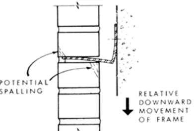
Damage to masonry as a result of rotation of the shelf angles (Figure 4), caused by downward movement of the frame in relation to the cladding, has also been reported. This can cause spalling at either the inner or outer edge of the joint because of local concentration of stress. It will also be a cause of eccentric loading on the facing wythe. Shelf angles should be stiff and firmly attached to the structure. One authority (5) recommends that they should not deflect anywhere, more than 1/16 in. under the weight of the masonry supported, usually the weight of one storey of brickwork. It is doubtful whether it would be practical to design shelf angles to meet these deflection requirements under the much larger forces caused by differential
Figure 4. Rotation of shelf angle owing to relative movement of frame.
Other effects of differential vertical movements such as vertical cracking may be observed at times, although they are often combined with those of horizontal shrinkage or expansion and difficult to diagnose. As well, the undesirable consequences of material movements may not be uniformly distributed over the whole of the building. Building size, shape and orientation, the proximity of panels to corners, the presence or absence of windows, time of year of
construction, and varying stress levels in the columns may have modifying effects. Continuous, narrow vertical strips of brick facing without edge support are particularly vulnerable to
buckling. Straight panels will be more stable than crooked ones. Some random movement is also due to the variable tightness of fit of the masonry to the shelf angles discussed before.
Avoiding Problems
An accepted way of avoiding build-up of compression in a brick facing is to leave a deliberate gap clear of any mortar below each shelf angle and substitute a flexible sealant for the pointing mortar at the toe of the angle (2, 3). In a recent state-of-the-art study Grimm (2) reviewed information for calculating the space required to avoid loading of panels. A gap of about 14, in. would be adequate, on the average, for a loft high panel on a reinforced concrete frame, but for a 90 per cent probability of movement not exceeding the space provided, a gap of ¼ in. would be needed. On steel frames the required gap would be smaller.
These measures will require close attention to coursing and the sizing of shelf angles to achieve the desired joint thickness. An adjustable shelf angle will almost certainly be needed. There will also be some additional cost, but it will be much less than that of saw cutting and caulking of joints in the future, as has been done to relieve stresses in some buildings. Other details may be developed to provide flexibility at the shelf angle joint. One such scheme leaves the joint open and extends a metal flashing downwards about 1 in. from the top of the angle to cover the joint.
It has been suggested also (3) that movement effects could be reduced in a reinforced concrete frame building by not starting the brickwork until the frame has been finished and by using only bricks that are not "kiln fresh." In both cases part of the materials movements would take place before the masonry is installed, but such measures may not be practical or controllable.
Ties
Properly placed ties are essential in both cavity and veneered walls to transmit lateral loads and to stabilize compressively loaded wythes. The minimum tie requirements of the National Building Code (7) should be carefully observed in design and construction. Technical data on the strength of ties are not extensive and until recently were scattered and difficult to find, but a thorough state-of-the-art report is now available (8).
Buckling and spalling failures of brick cavity walls and brick veneer cladding on high-rise buildings have occurred in recent years owing to differential movements between the frame and cladding. This Digest is intended to alert designers to this fact. It discusses the mechanism of failures and points out common construction features and design details that contribute to problems. Designing to accommodate dimensional changes and attention to details such as ties and anchors are recommended. Reference is also made to sources of design data on
movements and the strength and installation of ties.
References
1. Plewes, W. G. Vertical Movement of Building Frames and Cladding, in Cracks, Movements and Joints in Buildings. Nat. Res. Council of Canada, Div. Bldg. Res., NRCC 15477, Sept. 1976.
2. Grimm, C. T. Design for Differential Movement in Brick Walls. J. Struc. Div. Amer. Soc. Civ. Eng., Vol. 101, No. ST11, Nov. 1975, p. 2385-2403.
3. Foster, D. Further Observations on the Design of Brickwork Cladding to Multi-Storey RC Frame Structures. Brick Devel. Assoc., London, BDA Tech. Note 9, April 1975.
4. Suter, G. T. and J. S. Hall. How Safe Are Our Masonry Cladding Connections. Proc. First Can. Masonry Symp., Calgary, 1976. p. 95-109.
5. Technical Notes on Brick and Tile Construction, 18, 18A, 18B, Differential Movement, Cause and Effect. Brick Institute of America, April, May, June 1963.
6. Morstead, H. Construction Details and Their Effect on Building Behaviour. Proc., First Can. Masonry Symp., Calgary 1976, p. 200-222.
7. National Building Code of Canada, Supplement No. 4. Assoc. Com. Nat. Bldg. Code of Canada, NRCC 13989, 1975.
8. Grimm, C. T. Metal Ties and Anchors for Brick Walls. J. Struc. Div., Amer. Soc. Civ. Eng., Vol. 102, No. S74, April 1976.