The Click Modular Router
byEddie Kohler
BARKER MASSACHUSETTS INSTITUTE OF TECHNOLOGYAPR 2 4 2001
LIBRARIESS.B., Mathematics with Computer Science (1995); S.B., Music (1995)
S.M., Electrical Engineering and Computer Science (1997) Massachusetts Institute of Technology
Submitted to the Department of Electrical Engineering and Computer Science in partial fulfillment of the requirements for the degree of
Doctor of Philosophy at the
Massachusetts Institute of Technology February 2ooi
@
2ooo Massachusetts Institute of Technology All rights reservedSignature of author . . . . ... . . . . .'. .. . .
Department of Electrical Engineering and Computer Science Nkbvember 29, 2000
Certified by... .
M. Frans Kaashoek Associate Professor of Electrical Engineering and Computer Science Thesis Co-Supervisor Certified by . . . ... . . . .
Robert Morris Assistant Professor of Electrical Engineering and Computer Science Yhes Co-Siervisor Accepted by . . . .
Arthur C. Smith Chair, Department Committee on Graduate Students
The Click Modular Router
by Eddie Kohler
Submitted to the Department of Electrical Engineering and
Computer Science on November 30, 2000 in partial fulfillment of the
requirements for the degree of Doctor of Philosophy
ABSTRACT
Click is a new software architecture for building flexible and configurable routers. A Click router is assembled from packet processing modules called
elements. Individual elements implement simple router functions like packet
classification, queueing, scheduling, and interfacing with network devices. A router configuration is a directed graph with elements at the vertices; packets flow along the edges of the graph. Configurations are written in a declarative language that supports user-defined abstractions. This language is both read-able by humans and easily manipulated by tools. We present language tools that optimize router configurations and ensure they satisfy simple invariants.
Due to Click's architecture and language, Click router configurations are modular and easy to extend. A standards-compliant Click IP router has six-teen elements on its forwarding path. We present extensions to this router that support dropping policies, fairness among flows, quality-of-service, and transparent Web proxies. Each extension simply adds a couple elements to the base IP configuration. Other configurations, such as Ethernet switches, firewalls, and traffic generators, reuse many of the IP router's elements. Click software runs in the Linux kernel; on conventional PC hardware, its
maxi-mum loss-free forwarding rate for IP routing is 357,000 64-byte packets per
second, more than commercial routers with far greater cost. Configuration
optimization tools can raise this rate to 446,ooo 64-byte packets per second,
enough to handle several T3 lines and 95 % of our hardware's apparent limit.
Thesis Co-Supervisor: M. Frans Kaashoek Title: Associate Professor
Thesis Co-Supervisor: Robert Morris Title: Assistant Professor
Contents
i Introduction 2 Architecture 2. 1 Elements . . . . 2.2 Packets ... 2.3 Connections . . . .2.4 Push and pull . . . .
2.5 Packet storage...
2.6 CPU scheduling . . . .
2.7 Flow-based router context 2.8 Installing configurations 2.9 Element implementation 2.10 Discussion . . . . 3 Language 3.1 Syntax ... 3.2 Anonymous elements . . . 3.3 Configuration strings . . . 3.4 Compound elements . . . 3-5 3.6
Compound element argum Discussion and limitations
... . . . . .-. .-. .-. .-. .-. .-. .-. .-. .-. .-. .-. .-. .-. . . . . ents and overloading . . . . . 4 Elements 4.1 Overview . . . . 4.2 Classification . . . . 4.3 Scheduling . . . . 4.4 Dropping policies . . . . 4.5 Differentiated Services elements . . . . 4.6 IP rewriting . . . . 4.7 Information elements . . . . 8 14 15 16 17 21 21 22 24 25 z6 28 29 30 32 33 38 41 43 43 45 47 48 49 50 59
5 Routers 63
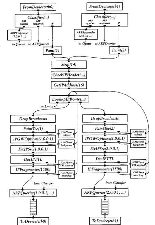
5.1 IP router . . . . 63
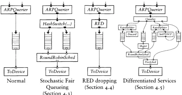
5.2 Extensions and subsets . . . . 66
5.3 Ethernet switch . . . . 69 5.4 Firewall . . . . 70 5.5 Transparent proxy . . . . . .. . . . .. 73 5.6 Traffic generator . . . . 75 6 Language tools 76 6.1 Pattern replacement . . . . 77 6.2 Fast classifiers . . . . 8o 6.3 Devirtualization . . . . 8z 6.4 Dead code elimination . . . . 84
6.5 Packet data alignment . . . . 85
6.6 Multiple-router configurations . . . . 87
6.7 Discussion . . . . 89
7 Implementation 90 7.1 Polling and device handling . . . . 91
8 Evaluation 93 8.1 Experimental setup . . . .. 93
8.z Forwarding rates . . . . 95
8.3 Overload behavior . . . . 98
8.4 CPU time breakdown . . . .02
8.5 Architectural overhead . . . 105
8.6 Differentiated Services . . . io6 8.7 Summary . . . 107
9 Related work io8 io Conclusion III A Element glossary 113 B Language grammar 120 B.i Lexical issues . . . . 120
Acknowledgements
This thesis describes joint work with Robert Tappan Morris, Benjie Chen, M. Frans Kaashoek, John Jannotti, and Massimiliano Poletto. Robert Morris wrote many of the IP router's elements, designed the IP router configuration, created push and pull processing, and was invaluable throughout. Benjie Chen did most of the polling and device driver work described in Section 7.1 and
helped create our evaluation testbed. John Jannotti implemented the Ether-net switch. Massimiliano Poletto implemented the FromLinux element and helped with the IPRewriter elements. Douglas S.
J.
De Couto contributed to the Click user-level software and inspired the ControlSocket element. Peilei Fan created a set of elements for IPv6, Thomer Gil implemented elements for flexibly measuring rates, and Alex Snoeren wrote some IPsec elements. I am also grateful to other Click users who submitted patches and suggested improvements: Richard Mortier (University of Cambridge Computer Labora-tory), Leigh Stoller (University of Utah), Saurabh Sandhir and Prem Gopalan (Purdue University), Brecht Vermeulen (Universiteit Gent), and Joe Elliott. John Wroclawski, David Black, and several anonymous reviewers made help-ful comments on papers describing some of the results presented here.Frans Kaashoek is a great advisor. I thank him inadequately and congrat-ulate him on graduating me despite obstacles.
I am very lucky, and deeply grateful, to have met these people, and thank them, for particular things and for everything.
M. Frans Kaashoek Robert Morris Janet Sonenberg
Marilyn, Ted, and Clarke Kohler Gina D'Acciaro
Ingrid V. Bassett Anna Rosenberg
Mathilda van Es
Nicolaas and Justin Kaashoek Paula Mickevich
Maria T. Sensale, Librarian and Notary Public Kristen Nummerdor Chrid Hockert
Sean Andrew Murray
Massimiliano Poletto David Mazieres Rosalba Perna Anne Dudfield Celeste Winant Chelle Gentemann Chris Onufryk Marcel Bruchez Rebecca Leonardson Elizabeth Stoehr Jesse Elliott Federica Pasquotto Regina Burris
Larisa Mann Julie Rioux Kris Grotelueschen
Dawson R. Engler Douglas S.
J.
De Couto John Jannotti Debby Wallach Jinyang Li Benjie Chen Neena LyallPaul Hsiao Sulaiman Mamdani Cora and Olaf Stackelberg
Paul Stackelberg David K. Gifford Martin Rinard Chuck Rachel Bredemeier Mark Stephenson Daniel Jackson Dorothy Curtis Blake Jeanne John Guttag Sam Larsen Barbara Liskov Alex Hartemink Darling Andrew Myers Mary Ann Ladd Ellen T.
Anna Frazer Elizabeth Michael Ouellette Peter Child
Mary Cabral Harris Rebecca Tyler Connors Edward Cohen Alan Brody
Jeremy Butler Julie Park Tara V. Perry Jeannie Sun Alan Pierson Charles Anand Sarwate Erin Lavik Armesto Darko Marinov Bing and Beverly Hollis Michelle Starz Nick Gaiano David Montgomery Katie Leo Lin-Ann Ching Rachael Bill Fregosi Diane Brainerd Andrea Zengion Ryan Kershner Jose Luis Andrade
Adam Glassman Sean Austin Stacy
J.
Pruitt Monica Gomi Jennifer Tsuei Butcher Ken Ed Darna Mike Katz Adriane Stebbins Marivi Acuia Rony Kubat Jesse Barnes Kortney Adams Rob Marcato Linda Tsang Earle Pratt MichlitschLeslie Cocuzzo Held Derik Pridmore Vanessa Thomas April Griffin Franz Elizondo-Schmelkes Premraj Janardanan Melanie Pincus Debora Lui Carolyn Chen
Kevin Simmons Peter Shulman Fernando Paiz Ricardo Tina Packer Joshua Goldberg Albert Fischer Aornawa Baker Geeta Dayal Janet Chieh Ramirez Sarah Joel Dawson Tom Cork Peter Cho Sean Levin Marketa Valterova Fernando Padilla Cohen
Jose Luis Elizondo Max Lord Chad Trujillo Forrest Larson Christie Moore
Geoff Brown Joanne Talbot Nancy Lynch Marilyn Pierce Monica Bell
I
Introduction
This thesis addresses a simple question: How should software for packet processors be designed?
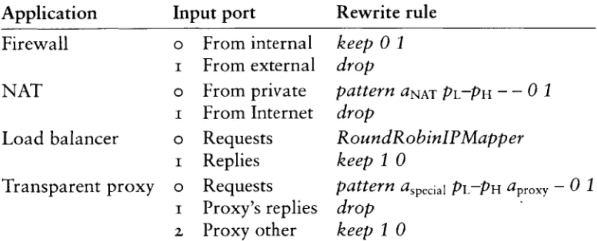
A packet-processing network consists, to first order, of routers and hosts. Hosts use packets as a means to an end; they are mostly concerned with providing communication abstractions to applications. Routers, however, are pure packet processing applications. They are interested only in packets, which they route from place to place based on packet header information. Routing was the first packet processing application on the Internet, but many others have come to light as the network has matured. Firewalls limit access to a protected network, often by dropping inappropriate packets. Network address
translators allow a large set of machines to share a single public IP address; they work by rewriting packet headers, and occasionally some data. Load balancers
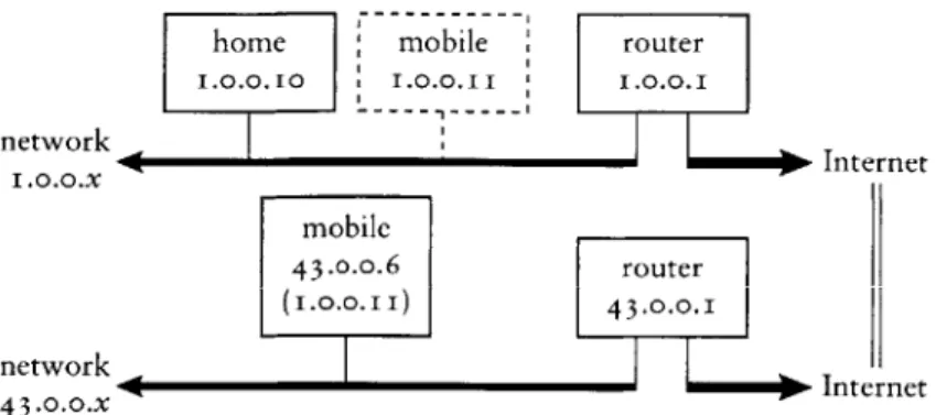
send packets to one of a set of servers, dynamically choosing a server based on load or some application characteristic. Other packet processors enforce quality-of-service policies, monitor traffic for planning purposes, detect hacker attacks or inappropriate use of resources, and support mobile hosts.
The packet processor abstraction is powerful and flexible because the In-ternet's network protocols generally maintain transparency. Communicating hosts can act as if they were connected by a wire; they don't care if that wire is actually interrupted by tens of hubs, switches, routers, and other packet processors. Implementing a new network-level application is as simple as dropping another packet processor onto the wire. Often, this requires no changes to other parts of the network.
The essential characteristic shared by all packet processors is the motion of packets. Packets arrive on one network interface, travel through the packet processor's forwarding path, and are emitted on another network interface. Contrast this with hosts, where packets lose their identity after they arrive: only data is transferred to the application. In packet processors, packets move
horizontally between peers, not vertically between application layers. The abstractions used to build a packet processor should explicitly support peer-to-peer packet transfer. Use of inappropriate abstractions, such as the inherently layered abstraction of procedure call, can result in unreadable code that is difficult to maintain.
Most software routers, to our knowledge, are built with inappropriate abstractions. All-software routers, such as the routers included with free UNIX operating systems, use procedure call exclusively, and mixed hard-ware/software routers use similar designs on their software paths. A router's forwarding path, however, is not easily broken into procedural units; forward-ing paths behave like pipelines through which packets flow. It is therefore hard to understand or change a procedural router design. Existing research on
mod-ular networking systems [zI, 29, 40] generally focuses on end node network
stacks and uses layered abstractions unsuitable for routers.
As a result, most routers today have closed, static, and inflexible designs. Network administrators may be able to turn router functions on or off, but they cannot easily specify or even identify the interactions of different func-tions. It is also difficult for network administrators and third party software vendors to extend a router with new functions. Extensions require access to software interfaces in the forwarding path, but these often don't exist, don't exist at the right point, or aren't published.
This thesis presents a modular architecture and software toolkit for build-ing routers and other packet processors. It was motivated by the extensibility and flexibility increasingly required of routers, and the wide and growing range of network applications naturally implemented by packet processors. We call this toolkit Click.
DESCRIPTION AND GOALS
Click routers are built from fine-grained software components called elements. To build a router configuration, the user chooses a collection of elements and connects them into a directed graph. The graph's edges represent possible paths for packet transfer. This layerless design was motivated by the peer-to-peer nature of packet processing. It also makes packet motion explicit and clear: packets move through the packet processor along the edges of the graph. Each router's forwarding path is implemented by a sequence of elements; this supports fine-grained extensions throughout, since the elements can be rearranged. To implement an extension, the user can write new elements or compose existing elements in new ways, much as UNIX allows one to
build complex applications directly or by composing simpler applications with pipes.
Click's design began from these principles:
- One rich, flexible abstraction. Click's single component abstraction is the element. Router configurations consist of elements connected together; there are no other component-level abstractions.
Because of this, the element abstraction affects how Click users think about router design. Click users tend to break packet processing applications into element-sized components; that is, they create modular designs because the element abstraction encourages it. Having one rich, flexible abstrac-tion makes this encouragement possible. If there were many abstracabstrac-tions designed for specific networking problems, rather than one abstraction designed for packet processing tasks in general, the system would feel less unified, and would be less likely to improve its users' coding habits.
- Configuration language. Click router configurations consist of a set of el-ements connected together. Configuration design, then, naturally divides into two phases: first, writing individual element classes, and then decid-ing which elements to use and how to connect them. Element classes are written in C++ using an extensive support library. A new programming language-called, unsurprisingly, Click-is used for designing router con-figurations.
The Click language is wholly declarative. It has features for declaring and connecting elements and for designing abstractions called compound
el-ements, and that is all. This contrasts with scripting languages like Tcl,
which are essentially general-purpose and, therefore, hard to analyze or manipulate. The Click language enforces hard separation between the roles of elements and configurations, leading to better element design. It makes router configurations human-readable and manipulable by automatic lan-guage tools. It has also kept the system as a whole both simple and clear.
- Avoid restrictions. The Click system guides users to create modular router and element designs by making modularity easy to achieve, but it does not prevent bad designs or restrict user flexibility. This means, for example, that nothing certain can be said about an element's semantics without looking at its source code. The hundreds of elements we have created share one mechanism for transferring packets, but nothing prevents new elements from inventing another. The advantage is that possibly useful behavior is never prevented by overly aggressive restrictions.
All these principles serve a single goal: programmability. We wanted Click to be easy and fun to program well. We have succeeded. Creating an ele-ment is more satisfying than writing task-specific network code because of the element's broader potential for reuse. Adding functionality to a router is exciting, especially when it takes just a single element. Click can inspire new applications as well: Section 4.6's description of the IPRewriter elements, and Section 5.5's illustration of a transparent Web proxy, led one reader to create a transparent DNS proxy. One year after the software's release, Click is used in at least five other universities. Click's programmability depends on the flexibility of its component architecture, its support library's ease of use, and the range of elements available by default. This thesis attempts to demon-strate programmability by example: Chapters 4 and 5 present many example elements and router configurations.
THESIS OVERVIEW
The first chapter of the thesis proper examines Click's architecture: the element abstraction, how packets pass through a router, how the CPU is scheduled, how configurations are installed, and so forth. It pays special attention to novel architectural features supporting programmability-for example, push and
pull processing, two complementary kinds of packet motion, and flow-based router context, which uses possible paths for packet motion to aid dependency
checking. Chapter 3 then describes the Click programming language, including its compound element mechanism for user-defined abstraction.
The next chapters examine specific elements and complete router config-urations. Chapter 4 presents elements for classification, packet scheduling, dropping policies, and TCP/IP rewriting, among others. Chapter 5 moves from elements to routers, describing a standards-compliant IP router and a wide variety of other configurations. Several sections show how adding a cou-ple elements to the IP router can change its queueing policy to, for examcou-ple, support quality-of-service, and how its elements are useful in widely different configurations, such as firewalls and traffic generators. These chapters address the heart of Click's programmability.
Chapter 6 describes automatic tools that understand, analyze, and modify router configurations in the Click language. Particular tools optimize router configurations, check them for errors, and ensure they satisfy simple prop-erties. Tools can implement transformations with no analogues in other net-working systems; one tool combines several component router configurations into a high-level description of an entire network, facilitating global opti-mizations and checks. Manipulating router configurations off line adds to
Click's power and extensibility. Through tools, optimizations and checks can be added without changing the core of the system.
Chapter 7 describes our implementation of the Click architecture, which runs as software on conventional PCs. No software router on conventional hardware can reach the multigigabit speeds achieved by expensive, custom-hardware routers designed for network backbones. However, many routers, particularly boundary routers at the edges of small to medium-sized organiza-tions, have lower performance requirements that can be achieved on conven-tional hardware, although with difficulty. Our performance goal was therefore to reach the limits of our hardware. Chapter 8 shows that we have achieved this goal. A Click IP router configuration, after applying language optimiza-tion tools, can route a peak of 446,ooo minimum-size packets per second in our tests. This is about 95% of the apparent hardware limit, enough to handle multiple T3 lines, and more than twice the maximum forwarding rate of a common edge router, the Cisco 7200 series, that costs about an order of magnitude more than our hardware.1
Finally, Chapter 9 describes related work and Chapter io concludes. There are two appendices: an element glossary in Appendix A describes all the elements mentioned in the text; Appendix B contains a BNF grammar for the Click language.
SUMMARY The contributions of this thesis include:
- The Click architecture, especially flow-based router context and push and pull processing;
- The Click language and its compound element abstraction;
- Particular elements, including packet schedulers, dropping policies, classi-fiers, and the IPRewriter set of elements for flexible TCP/IP rewriting; - A standards-compliant IP router written in Click;
- Examples of other configurations and IP router extensions, demonstrating Click's flexibility;
i. Of course, the Cisco router presumably has better reliability. It also has more features, although, outside of better routing table support, most of these features are probably not on the forwarding path.
- Tools that optimize routers and check high-level system properties by
an-alyzing and manipulating files in the Click language;
- A thorough analysis of Click's performance on PC hardware;
- and the Click software itself.
This thesis describes release i.i of the Click software. This and previous
releases are available online for download at http: //www. pdos .1 cs .mi t. edu/
2
Architecture
Click is an extensible toolkit for writing packet processors. This toolkit's archi-tecture serves an important function: determining the design space available for its components. We therefore open our discussion of Click by examining its architecture and, in particular, the features it provides for components' use. In later chapters, we turn to examples of individual components and actual Click router configurations.
A quick overview: The Click architecture is centered on the element. Each element is a software component representing a unit of router processing. Elements perform conceptually simple computations, such as decrementing an IP packet's time-to-live field, rather than large, complex computations, such as IP routing. They generally examine or modify packets in some way; packets, naturally, are the particles of network data that routers exist to process. At run time, elements pass packets to one another over links called connections. Each connection represents a possible path for packet transfer. Click router
configurations are directed graphs of elements with connections as the edges.
Router configurations, in turn, run in the context of some driver, either at user level or in the Linux kernel.
Figure 2.1 shows some elements connected together into a simple router configuration. Elements appear as boxes; connections appear as arrows con-necting the boxes together. Other features of the diagram are described in later sections. Packets pass from element to element along the arrows (connections). This router's elements read packets from the network (FromDevice(etb0)),
count them (Counter), and finally throw them away (Discard).
The rest of this chapter examines the Click architecture's components in detail. We start with elements, packets, and connections, then move on to more specific features like push and pull processing. Later sections examine CPU scheduling and packet storage in Click, show how router configurations are installed, and present the C++ implementation of a simple element class.
elements
FromDevice(eth-) Counter Discard
connections
FIGURE 2..i-A simple Click router configuration.
2..1 ELEMENTS
The element is the most important user-visible abstraction in Click. Every property of a router configuration is specified either through the choice of ele-ments or through their arrangement. Device handling, routing table lookups, queueing, counting, and so forth are all implemented by elements. Inside a running router, each element is a C++ object that may maintain private state.
Elements have five important properties: element class, ports, configuration strings, method interfaces, and handlers.
- Element class. An element's class specifies that element's data layout and behavior. For example, the code in an element class determines how many ports elements of that class will have, what handlers they will support, and how they will process packets. In C++, each element class corresponds to a subclass of El ement.
- Ports. Each element can have any number of input and output ports. Every connection links an output port on one element to an input port on another. Different ports may have different roles; for example, many elements emit normal packets on their first output port and erroneous packets on their second. The number of ports provided by an element may be fixed, or it
may depend on the element's configuration string or how many ports were used by the configuration. Every port that is provided must be used by at least one connection, or the configuration is in error. Ports may be push, pull, or agnostic; these terms are defined in Section 2.4.
- Configuration string. The optional configuration string contains additional arguments passed to the element at router initialization time. For many element classes, configuration strings define per-element state and fine-tune
element behavior, much as constructor arguments do for objects.
Lexically, a configuration string is a list of arguments separated by commas. Most configuration arguments fit into one of a small set of data types: IP addresses, for example, or integers, or lists of IP addresses.
element class
input port --- Tee(2) :::- output ports
configuration string
FIGURE 2.z-A sample element.
- Method interfaces. Each element exports methods that other elements may access. This set of methods is grouped into method interfaces.
Every element supports at least the base method interface, which contains, for example, methods for transferring packets. Elements can define and implement arbitrary other interfaces on top of this; for example, Click's
Queue element, which implements a FIFO packet queue, exports an
inter-face that reports its current length.
- Handlers. Handlers are methods that are exported to the user, rather than to other elements in the router configuration. They support simple, text-based read/write semantics, as opposed to fully general method call se-mantics. For example, the Queue element mentioned above has a handler that reports its current length as a decimal ASCII string, and the Counter element in Figure 2. 1 provides a handler so users can access its current count.
In the Linux kernel driver, handlers appear as files in the dynamic /proc file system. At user level, handlers may be accessed via a TCP/IP-based protocol.
Figure 2.z shows how we diagram these properties for a sample element,
Tee(2). 'Tee' is the element class; a Tee copies each packet received on its
single input port, sending one copy to each output port. We draw input ports as triangles and output ports as rectangles. Configuration strings are enclosed in parentheses: the '2' in 'Tee(2)' is interpreted by Tee as a request for two outputs. Method interfaces and handlers are not shown explicitly; they are specified implicitly by the element class.
The element glossary in Appendix A provides a quick description of Tee and every other element class mentioned in the text.
2.2 PACKETS
A Click packet consists of a small packet header and the actual packet data; the packet header points to the data. This structure was borrowed from the
Linux kernel's packet abstraction, sk_buf f. In the Linux kernel driver, Click packet objects are equivalent to skbuffs, which avoids translation or indi-rection overhead when communicating with device drivers or the kernel itself. This equivalence is hidden behind a C++ class, Packet. Other drivers reim-plement this interface; the user-level driver, for example, has a hand-written Packet implementation. Thus, elements may be compiled for either driver without change. Operations on an in-kernel Packet have zero overhead over the corresponding Linux sk_buff operations.
Several packet headers may share the same packet data. When copying a packet-for example, with a Tee element-Click produces a new packet header that shares the original data. Shared packet data is copy-on-write. Elements that modify packet data first ensure that it is unshared; if it is shared, the element will make a unique copy of the data and change the packet header to point to that copy. Packet headers are never shared, however, so header modifications never cause a copy.
Headers contain a number of annotations in addition to a pointer to the packet data. Annotations may be shared with Linux or specific to Click. Some annotations contain information independent of the packet data-for exam-ple, the time when the packet arrived. Other annotations cache information about the data. For example, the CheckIPHeader element sets the IP header annotation on passing IP packets. This annotation marks both where the IP header begins and where the IP payload begins, freeing later elements from examining the IP header's length field. Annotations are stored in the packet header in a fixed static order; there is currently no way to dynamically add a new kind of annotation.
Packet data is stored in a single memory buffer. This differs from the BSD-style mbuf structure, where data is stored in a linked chain of buffers. Compared to mbufs, Linux and Click's model allows simpler, faster access in the common case, at the cost of occasional packet copies when prepending or appending more data than will fit into a particular buffer. Such copies do not occur in our tests.
2.3 CONNECTIONS
A connection passes from an output port on one element to an input port on another. Connections are the main mechanism used for linking elements together; each connection represents a possible path for packet transfer be-tween elements. In a running router, connections are represented as pointers to element objects, and passing a packet along a connection is implemented by a single virtual function call.
Connections are drawn as arrows; each arrow's direction represents the direction of packet flow. Each connection links a source port to a destination
port. The source port is always an output port, and the destination port is
always an input port. We also use source element and destination element with the obvious definitions.
Router configurations may be seen as directed graphs with elements as
vertices. However, connections link ports, not elements, and each element may have many ports. A more complete model treats router configurations as directed graphs with ports as vertices. Port graphs such as this have two kinds of directed edges, ordinary connections and internal edges. Internal edges show how packets may flow from input ports to output ports within a single element; an internal edge from an element's input port i to its output port o means that a packet that arrived on input port i might be emitted on output port o. In the simplest model, every element has a complete graph of internal edges-that is, there are internal edges linking every input to every output. This is not always appropriate, however. For some elements, packets arriving on a given input might be emitted on only a subset of outputs, or perhaps on none at all. More specific internal edge information helps the system decide which elements are reachable from a given port; in the long run, it will also help check properties of configurations. Click elements can therefore specify detailed internal edge information if they choose.
If a path exists from an output port o to an input port i in the port graph representation of a router configuration, then we say that i is downstream of
o, and, conversely, that o is upstream of i. This notion may also be generalized
to elements.
2.4 PUSH AND PULL
Click supports two kinds of connections, push and pull, that implement com-plementary kinds of packet transfer. On a push connection, packets start at the source element and are passed downstream to the destination element. On a pull connection, in contrast, the destination element initiates packet transfer: it asks the source element to return a packet, or a null pointer if no packet is available. Many software routers provide only push connections; Clark called pull connections upcalls [8].
These forms of packet transfer are implemented by two virtual function calls, push and pul 1. Neither kind of call is ever intended to block. For in-stance, a pul1 call reaching an element with no packet ready should immedi-ately return a null pointer rather than waiting for some packet to arrive. Click is currently single-threaded, so a blocking design would simply hang.
receive Nuhl PUl >Te)
packet p
return enqueue p
return ready to
etransmit
and return itr setn
dequuepretun ~ send p
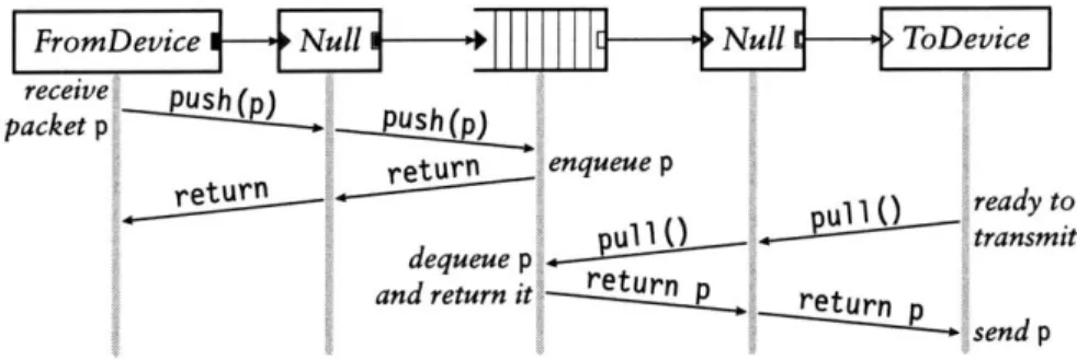
FIGURE 2.3-Push and pull control flow. This diagram shows functions called as a packet moves through a simple router; time moves downwards. During the push, control flow starts at the receiving device and moves forward through the element graph; during the pull, control flow starts at the transmitting device and moves backward. The packet p always moves forward.
The type of a connection is determined by the ports at its endpoints. Each port in a running router is either push or pull. Connections between two push ports are push, and connections between two pull ports are pull; connections between a push port and a pull port are illegal. Elements set their ports' types as the router is initialized. They may also create agnostic ports, which behave as push when connected to push ports and pull when connected to pull ports. In our configuration diagrams, black ports are push and white ports are pull; agnostic ports are shown as push or pull ports with a double outline.
Figure 2.3 shows how push and pull work in a simple router. This router
forwards packets unchanged from one network interface to another. The central element in the figure is a Queue. This element enqueues packets on a FIFO queue as they are pushed to its input, and yields packets from the front of that queue as it receives pull requests on its output. The two Null elements, which pass packets through unchanged, demonstrate agnostic ports.
Push connections are appropriate when unsolicited packets arrive at a Click router-for example, when packets arrive from a device. The router must handle such packets as they appear, if only to queue them for later con-sideration. Pull connections are appropriate when the Click router needs to control the timing of packet processing. For example, a router may transmit a packet only when the transmitting device is ready. In Click, transmitting de-vices are elements with one pull input. They use pull requests to initiate packet transfer only when ready to transmit. Agnostic ports model the common case that neither kind of processing is inherently required.
Pull connections also model the scheduling decision inherent in choosing the next packet to send. A Click packet scheduler is simply an element with multiple pull inputs and one pull output. It responds to a pull request by
FromDevice
C~o ter ToD evice
FromDevice 1-4- ToDevice
FIGURE z.4-Push and pull violations. The top configuration has four errors: (i)
FromDe-vice's push output connects to ToDeFromDe-vice's pull input; (z) more than one connection from FromDevice's push output; (3) more than one connection to ToDevice's pull input; and (4) an
agnostic element, Counter, in a mixed push/pull context. The bottom configuration, which includes a Queue, is legal. In a properly configured router, the port colors on either end of each connection will match.
choosing one of its inputs, making a pull request to that input, and returning the packet it receives. (If it receives a null pointer, it will generally try another input.) These elements make only local decisions: different scheduling behav-iors correspond to different algorithms for choosing an input. Thus, they are easily composable. Section 4.3 discusses this further.
The following properties hold for all correctly configured routers: Push outputs must be connected to push inputs, and pull outputs must be connected to pull inputs. Each agnostic port must be used as push or pull exclusively. Furthermore, if there is an internal edge linking an agnostic input port to an agnostic output port on the same element, then the ports must be either both push or both pull. Finally, push outputs and pull inputs must be connected exactly once; this ensures that each packet transfer request-either pushing to an output port or pulling from an input port-uses a unique connection. These properties are automatically checked by the system during router initialization. Figure 2.4 demonstrates some violations.
Configurations that violate these properties tend to be intuitively invalid. For example, the connection from FromDevice to ToDevice in Figure 2.4 is
illegal because FromDevice's output is push while ToDevice's input is pull. But this connection is intuitively illegal, since it would mean that ToDevice might receive packets that it was not ready to send. The Queue element, which converts from push to pull, also provides the temporary packet storage this configuration requires.
Some further notes on agnostic ports: Agnostic ports may be connected to other agnostic ports. At initialization time, the system will propagate con-straints until every agnostic port has been assigned to either push or pull. To support agnostic ports, an element designer might write both a push function and a pul 1 function; only the relevant function will be called. Alternatively, the
designer can write a single simpl e_action method. This causes each packet transfer to that port to take two virtual function calls rather than one-the first reaches a generic push or pul 1, which, in turn, calls simpl e_acti on.
2-5 PACKET STORAGE
Click elements do not have implicit queues on their input and output ports or the associated performance and complexity costs. Instead, queues in Click are implemented by a separate, explicit Queue element. This gives the router designer control over an important router property: how packets are stored. It also enables valuable configurations that are difficult to arrange otherwise-for example, a single queue feeding multiple devices, or a queue feeding a traffic shaper on the way to a device. Each Queue has a push input port and a pull output port; the input port responds to pushed packets by enqueueing them, and the output port responds to pull requests by dequeueing packets and returning them. Queue never actively passes packets through the graph-it never calls another element's push or pul 1 function. Instead, and in accord with intuition, it exclusively reacts to requests from other elements. This design would be impossible without support for both push and pull connections: only the combination of push and pull allows Queue to be entirely reactive.
The user can choose a different storage policy than simple FIFO queueing simply by using a different element. For example, Queue drops packets from its tail when it is full. The FrontDropQueue element is mostly equivalent to
Queue except that, when full, it drops packets from its head to make room
for new packets at its tail.
2.6 CPU SCHEDULING
Click schedules the router's CPU with a task queue. Each router thread runs a loop that processes the task queue one element at a time. The task queue is scheduled with the flexible and lightweight stride scheduling algorithm [45]. Tasks are simply elements that would like special access to CPU time. Thus, elements are Click's unit of CPU scheduling as well as its unit of packet processing. An element should be on the task queue if it frequently initiates push or pull requests without receiving a corresponding request. For example, an element that polls a device driver should be placed on the task queue; when run, it would remove packets from the driver and push them into the configuration. However, most elements are never placed on the task queue. They are implicitly scheduled when their push or pul 1 methods are called. Once an element is scheduled, either explicitly or implicitly, it can initiate an
arbitrary sequence of push and pull requests, thus implicitly scheduling other elements.
Click currently runs in a single thread. Thus, any push or pu] 1 packet transfer method must return to its caller before another task can begin. The router will continue to process each pushed packet, following it from element to element along a path in the router graph, until it is explicitly stored or dropped. Similarly, the router will continue to process each pull request until a packet is found. The placement of Queues in a configuration graph therefore determines how CPU scheduling may be performed. For example, if Queues
are far away from input device elements in the graph, the router must do a lot of work on each input packet before processing the next input packet:
specifically, it must push the packet to a Queue.
This design can suffer infinite loops caused by circular configurations. Currently, the user is expected to avoid infinite loops, although we eventually plan to write a language tool that flags potential problems. However, not every circular configuration is problematic. Consider an element that generates error packets in response to all packets that aren't errors themselves. Such an element could be placed safely in a circular configuration since it doesn't respond to packets it generates. This happens in practice with ICMPError elements and our IP router; see Section 5.1.
Another task structure handles timer events. Each element can have any number of active timers; each timer calls an arbitrary method when it fires.
2.7 FLOW-BASED ROUTER CONTEXT
If an element a wants to call a method on another element b, it must first locate
b. Connections solve this problem for packet transfer, but not for other method
interfaces. Instead, a can refer to b by name (for example, a's configuration string could contain the string "b"), or it can use an automatic mechanism
called flow-based router context.
Flow-based router context is simply an application of depth- or breadth-first search to router configuration graphs. A search starting at an element and moving downstream describes where packets starting at a given element might end up. Similarly, a search starting at an element and moving upstream describes where packets arriving at that element might have originated. This generalizes connections, which specify where a packet might travel in exactly one transfer.
To use flow-based router context, elements ask the system questions such as "If I were to emit a packet on my second output, where might it go?" Elements may restrict this question to a subset of the configuration-namely,
R ED Classifjier Di scard
Strip-FIGURE 2--5-Flow-based router context. A packet starting at RED and stopping at the first
Queue it encountered might pass through any of the grey elements.
those elements that implement a certain method interface. For example, an element might ask "If I were to emit a packet on my second output, which
Queues might it encounter?" It may further restrict the answer to the closest
method interfaces: "If I were to emit a packet on my second output, and it stopped at the first Queue it encountered, where might it stop?" This occupies a useful middle ground between purely local information (connections) and purely global information (the entire router). It can be more robust than naming elements explicitly, since it automatically adapts to changes in the
router configuration. It also captures a fundamental router property: if two elements interact, then packets can usually pass from one to the other.
Dropping policies provide one example of flow-based router context in practice. Each Queue exports its current length using a method interface. Elements such as RED (a dropping policy element described further in Sec-tion 4.4) are interested in this informaSec-tion; RED therefore locates one or more relevant Queues using flow-based router context. Figure 2. 5 shows the router context downstream of a RED element. Every element in the figure is down-stream of RED, but only the grey elements are relevant if the search stops at the closest Queues. Thus, RED's flow-based router context search will return the two grey Queues.
Flow-based router context is robust in the presence of cycles in the config-uration graph. Elements generally ask for flow-based router context once, at router initialization time, and save its results for quick reference as the router runs. Any element that uses flow-based router context must be prepared to handle zero, one, two, or more result elements, possibly by reporting an error if there are too many or too few results. Section 4.4 demonstrates the flexibility benefits of handling any number of results.
Flow-based router context can be insufficiently precise for some applica-tions. For example, the user might want the RED element in Figure z- 5 to use only one of the grey Queues, or to use a different Queue entirely. RED and
other elements therefore let the user override flow-based router context with an explicit list of element names.
Click currently uses flow-based router context mostly to check assertions-that a needed element is somewhere downstream, for example. When used this way, there is no risk of finding the wrong elements, and flow-based router
context simply improves the system's ability to detect configuration errors.
2.8 INSTALLING CONFIGURATIONS
Click configurations run inside a driver, which implements facilities used by all elements. There are currently two drivers: the user-level driver runs as an application at user level, and the Linux kernel driver runs as a downloadable module in the Linux kernel. The user-level driver is useful for debugging and running repeatable tests; it can even receive packets from the network, using OS mechanisms originally designed for packet sniffers. However, it cannot prevent the operating system's networking stack from handling a packet. The kernel driver can completely replace the OS networking stack, changing a conventional PC into an arbitrary router. This driver can also achieve high performance for PC hardware; see Chapters 7 and 8.
The user installs a Click configuration by writing its definition in a simple textual language and passing that definition to the appropriate driver. (Chap-ter 3 describes this language in detail.) The driver then parses the definition, checks it for errors, initializes every element, and puts the router on line. It breaks the initialization process into stages. In the early stages, elements set object variables, add and remove ports, and specify whether those ports are push or pull. In later stages, they query flow-based router context, place themselves on the task queue, and, in the kernel driver, attach to Linux kernel structures. This staged design supports cyclic configurations better than any fixed initialization order, which might fall prey to circular dependencies.
To run a configuration in the user-level driver, the user simply runs a click application, passing a configuration file's pathname on the command line. Arbitrary numbers of user-level drivers can be active simultaneously.
The Linux kernel driver's installation policy is slightly more complex due to its location in the kernel. This kernel driver runs one router configuration at a time. To install a configuration, the user writes a Click-language description to the special file /proc/cl i ck/confi g. Installing a new configuration normally destroys any old configuration; for instance, any packets stored in old queues are dropped. This starts the new configuration from a predictable empty state. However, Click supports several techniques for changing a configuration without losing information:
- Handlers. Some elements allow the user to reconfigure them with handlers as the router is running. Handler modifications are generally local to an element. For example, the Queue element has a handler that changes its maximum length, and a Click routing table element would likely provide
addroute and delroute handlers as access points for user-level routing protocol implementations.
- Hot swapping. Some configuration changes, such as adding new elements, are more complex than handlers can support. In these cases, the user can write a new configuration file and install it with a hot-swapping option. This will only install the new configuration if it initializes correctly-if there are any errors, the old configuration will continue routing packets without a break. Also, if the new configuration is correct, it will atomically take the old configuration's state before being placed on line; for example, any enqueued packets are moved into the new configuration. This happens only with element classes that explicitly support it, and only when the new elements have the same names as the old ones.
- New element classes. Element class definitions can be added to and moved from a running Click kernel driver. A Click configuration can re-quire a particular set of elements with a rere-quire statement; when that configuration is installed, the driver will automatically load an object file containing those elements. This feature could be used to support active net-working, where packets can refer to specialized per-packet routing code. In Click, that code could consist of elements that are added to the driver dy-namically; a new configuration using those elements could be hot-swapped in.
2.9 ELEMENT IMPLEMENTATION
Each Click element class corresponds to a subclass of the C++ class El ement, which has about zo virtual functions. El ement provides reasonable default implementations for many of these, so most subclasses must override six of them or less. Only three virtual functions are used during router operation, namely push, pul 1, and run_s chedul ed (used by the task scheduler); the others are used for identification, push and pull specification, configuration, initial-ization, handlers, and so forth.
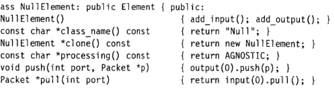
Subclasses of El ement are easy to write, so we expect that users will easily write new element classes as needed. In fact, the complete implementation of a simple working element class takes less than i lines of code; see Figure 2.6.
class NullElement: public Element { public:
NullElement() { add_i nput(); add_output(); }
const char *classname() const { return "Null"; }
NullElement *clone() const { return new NullElement; }
const char *processing() const { return AGNOSTIC; } void push(int port, Packet *p) { output(O).push(p); }
Packet *pull(int port) { return input().puli(); I
};
FIGURE 2.6-The complete implementation of a do-nothing element: Null passes packets from its single input to its single output unchanged.
Most elements define functions for configuration string parsing and initial-ization in addition to those in Figure z.6, and take about izo lines of code. When linked with ioo common elements, the Linux kernel driver contains
roughly 14,000 lines of core and library source code and 19,ooo lines of el-ement source code (not counting comments); this compiles to about 341,000 bytes of i3 86 instructions, most of which are used only at router initialization
time. A simple element's push or pul l function compiles into a few dozen i386 instructions.
2.10 DISCUSSION
Click users will generally prefer fine-grained elements, which have simple spec-ifications, to coarse-grained elements with more complex specifications. For IP routing, for example, a collection of small elements is preferable to a single element, since the collection of small elements supports arbitrary extensions and modifications through configuration graph manipulation. However, small elements are not appropriate for all problems. Coarse-grained elements are required when control or data flow doesn't match the flow of packets. For ex-ample, complex protocol processing often requires a coarse-grained element; a routing protocol like BGP does not naturally break into parts among which
packets flow.
A conventional router contains shared structures that don't participate in packet forwarding, such as routing tables, network statistics, and so forth. In Click, these structures are more naturally incorporated into the packet forwarding path. Routing tables, such as the IP routing table and the ARP cache, are encapsulated by elements that make routing decisions, and statistics are localized inside the elements responsible for collecting them. Of course, these elements can export method interfaces so other elements can access the structures.
Several other modular networking systems are built around an abstraction that represents individual network flows-TCP sessions and the like [21, 29]. These systems automatically create and destroy modules as network flows are encountered. This is a fast, limited form of configuration installation, as each new or deleted flow changes a localized section of the configuration. Hot-swap installation is fast in Click-on a 700 MHz Pentium III, installing a 50-element configuration takes less than a tenth of a second-but not fast enough to support flow creation and deletion. Most of the benefits of a flow-based design can be realized in Click as is; many configurations only require per-flow-class state and CPU scheduling, and elements can cooperate to maintain per-flow private state. Unlike flow-based systems, however, Click cannot schedule the CPU per individual flow.
3
Language
The Click programming language textually describes Click router configura-tions. Two of its constructs are sufficient to describe any configuration graph:
declarations create elements and connections connect elements together.
How-ever, a language with only these constructs would scale poorly to large config-urations. Click's language contains additional structure to aid users: syntactic sugar improves readability, and compound elements, described in Section 3.4, provide an abstraction mechanism for configuration fragments.
Two goals guided the language's design, readability and convenience for
tools. The importance of readability is clear enough; a modular networking
system is only extensible as far as its configurations may be easily read and modified. The second goal, convenience for tools, means that it should be easy to design, use, and compose automatic tools that analyze and manipulate Click language files. Tools like this can optimize or transform Click configurations or ensure that application-level properties hold; see Chapter 6. We prefer a broad, open-ended set of tools to one tool, no matter how powerful that tool. For example, the Ensemble system for composing network protocol stacks [24] is built around a single tool, a theorem prover. It can perform checks and optimizations, but only with extensive human intervention. In Click, we chose to sacrifice the kind of correctness guarantees achievable with theorem proving for ease of use and ease of tool design.
These goals led us to a set of more concrete design principles.
- The language is declarative: it simply describes the configuration graph. Contrast this with scripting as embodied by Tcl, where directives for ma-nipulating a system are added to a general-purpose programming language. The Berkeley ns network simulator
[33]
uses Tcl as a base; ns configura-tions are embedded in, and inseparable from, imperative Tcl scripts that may perform other arbitrary actions. Declarative languages have readabil-ity advantages, and declarative programs can be analyzed and manipulatedmore easily than imperative programs.
- The language is simple. We have kept new constructs to a minimum, prefer-ring to implement language extensions through special-purpose elements. This choice limits the mechanisms that users must learn and tools must implement while achieving great flexibility.
- Click-language programs and configuration graphs are equivalent. Any configuration corresponds to a simple program in the Click language, and it is easy to translate back and forth between programs and graphs.
- Tools should not need to fully understand Click's semantics-for example, they should not have to understand what every element does. Therefore, the language supports blind manipulation: tools that do not understand element semantics can transform configuration programs while preserving correctness.
The rest of this chapter describes the language we have designed based on these principles: its syntax, its abstraction mechanisms, and its limitations.
3.1 SYNTAX
Again, a configuration graph consists of elements connected together. Each element has an element class, which is specified by name, and optionally a configuration string. Elements are connected through their input and output ports. In the Click language, input and output ports are distinguished by number and elements are distinguished by name. Each element in the config-uration has a unique name that the user can optionally specify. These names distinguish elements during the parsing process, and also let the user, or other programs, access particular elements once the configuration is running.
The language's fundamental constructs, declarations and connections, have the following syntax:
name :: class (config-string);
//
declaration namer [portr] -> [port2] name2;//
connection(All semicolons are optional.) The connection statement "namer [porti] ->
[port2] name2" creates a connection from namer's output port porti to
name2's input port port2. Elements must be declared before they are used in
connections. Any configuration can be described with these two statements, but additional syntactic sugar makes configurations more pleasant to write and to read:
//
Declare three elements ...src :: FromDevice(ethO);
ctr Counter;
sink Discard;
//
... and connect them togethersrc -> ctr; ctr -> sink;
FIGURE 3.i-A Click-language description of the trivial router of Figure z.i (page 15).
class;
-> name2;
[porti] ->
//
can omit empty configuration string//
omitted port numbers are equivalent to [0][port2a] namez [port2b] -> [port3] name3;
//
can piggyback connections class (config-string) -> name3;//
can declare elements inside connectionsA final syntactic sugar, the anonymous element declaration, is described in the next section.
An additional contstruct, the requi re statement, lists configuration re-quirements. Its syntax is as follows:
requi re (requirement [, requirement ..
.3);
As mentioned in Section z.8, the Click drivers treat each requirement as a dynamically linked object, possibly containing new element definitions, that should be loaded before the rest of the configuration is parsed.
Lexically, C++-style comments (both '/* ... */' and '// ... end of line') are
treated as whitespace. Click language parsers also recognize C preprocessor-style line directives ('# line-number "filename"') and use them to generate reasonable line numbers for error messages. Language manipulation tools include relevant line directives in their output programs.
Figure 3.1 uses these constructs to define a trivial router. For reference, Appendix B provides a full BNF grammar for the language.
3.2. ANONYMOUS ELEMENTS
Anonymous element declarations let the user create elements without specify-ing their names. Such elements can be used in at most two connections, once as input and once as output. For example:
name : namei namei
FromDevice(ethO) -> Counter -> Discard;
FIGURE 3.2--Another Click-language description of the trivial router of Figure 2.1.
namei -> class (config-string) -> name2;
//
one input, one outputname -> class (config-string) ;
//
input onlyclass (config-string) -> name;
//
output onlyclass (config-string);
//
no inputs or outputsAs usual, empty configuration strings can be omitted. The system constructs a name for each anonymous element; these names have the form 'class@i', where
i is an integer chosen to ensure uniqueness. Anonymous element declarations
improve readability by avoiding clutter. A language without anonymous decla-rations could be compared, albeit with some exaggeration, to a programming language in which each subexpression had to be uniquely named. Typical Click configurations use anonymous declarations for half their elements. The
Click-language description in Figure 3.2 is equivalent to Figure 3.1, but uses
anonymous elements.
Besides making configurations more readable, anonymous elements pro-vide an excellent means for implementing language extensions. For example, how might the user set the scheduling priority for an element, or define an abbreviation for a common network address? The obvious solution would involve extended syntax:
address ethOaddr = 00:eO:98:09:ab:af;
arpq :: ARPQuerier(18.26.4.44, ethOaddr);
arpq -> td :: ToDevice(ethO) priority 10;
However, this adds unnecessary complexity to the language and does not generalize well. Instead, Click implements extensions through special
infor-mation elements-ordinary elements whose configuration strings define some
extension property. For example:
AddressInfo(eth0_addr 00:eO:98:09:ab:af);
arpq :: ARPQuerier(18.26.4.44, ethOaddr);
arpq -> td :: ToDevice(ethO);
ScheduleInfo(td 10);
The Address Info and Schedul eInfo statements are ordinary anonymous ele-ment declarations. Information eleele-ments are described further in Section 4.7. The generated names of anonymous elements are valid identifiers in the language. Thus, a tool can parse a program that uses anonymous elements and