HAL Id: tel-03211049
https://hal.archives-ouvertes.fr/tel-03211049
Submitted on 28 Apr 2021
HAL is a multi-disciplinary open access archive for the deposit and dissemination of sci-entific research documents, whether they are pub-lished or not. The documents may come from teaching and research institutions in France or abroad, or from public or private research centers.
L’archive ouverte pluridisciplinaire HAL, est destinée au dépôt et à la diffusion de documents scientifiques de niveau recherche, publiés ou non, émanant des établissements d’enseignement et de recherche français ou étrangers, des laboratoires publics ou privés.
Reforming of toluene formed during the gasification of
biomass with alumina based catalysts prepared by
aqueous sol-gel processes.
Vincent Claude
To cite this version:
Vincent Claude. Reforming of toluene formed during the gasification of biomass with alumina based catalysts prepared by aqueous sol-gel processes.. Chemical engineering. Université de Liège, 2017. English. �tel-03211049�
UNIVERSITÉ DE LIÈGE Faculté des Sciences Appliquées Department of Chemical Engineering Nanomaterials, Catalysis and Electrochemistry
Reforming of toluene formed during the
gasification of biomass with alumina based
catalysts prepared by aqueous sol-gel processes
Dissertation présentée par
Vincent CLAUDE
le mardi 14 Février 2017 en vue de l’obtention du grade de Docteur en
Sciences de l’Ingénieur
Composition du jury :
Benoît Heinrichs, Professeur à l’Université de Liège, Président
Stéphanie Lambert, Chercheur qualifié FRS-FNRS, Chargé de cours adjoint à l’Université de Liège, Promotrice
Dominique Toye, Professeur à l’Université de Liège Grégoire Léonard, Chargé de cours à l’Université de Liège Jean-Paul Pirard, Professeur Émérite à l’Université de Liège Claire Courson, Maître de Conférences à l’Université de Strasbourg Sébastien Testu, Enseignant-Chercheur à l’Université de Lorraine
Remerciements
Cette thèse de doctorat s’inscrit dans le contexte général des travaux de recherche effectués au Department of Chemical Engineering - Nanomaterials, Catalysis and Electrochemistry de l’Université de Liège (ULg-NCE). Cette thèse a été financée par le FRS-FNRS, dans le cadre du crédit FRFC n°2.4541.12 (2012-2016).
Je tiens à remercier très vivement Dr. Stéphanie Lambert-Jamoulle, Chercheur qualifiée FRS-FNRS, Chargée de cours adjointe et promotrice de ce travail. Je la remercie de m’avoir proposé un sujet aussi vaste que la synthèse de catalyseurs par voie sol-gel pour le reformage catalytique de goudrons lors de la gazéification de la biomasse. Je lui exprime ma reconnaissance pour la rigueur scientifique à laquelle elle m’a formé, ainsi que pour le temps qu’elle a consacré à la définition des objectifs, à la planification des expériences, à l’analyse critique des résultats et à la supervision de la rédaction de la thèse et des articles parus dans les journaux scientifiques.
Je remercie Pr. Benoît Heinrichs, Pr. Dominique Toye et M. Christian Meyers pour leur encadrement et leurs conseils pertinents tout au long de ce doctorat.
Lors des réunions scientifiques internes au laboratoire, j’ai eu la chance de recevoir de nombreuses et judicieuses suggestions émises par Dr. Christelle Alié, Dr. Cédric Calberg, Dr.
Ludivine Tasseroul, Dr. Carlos Paez, Dr. Sigrid Douven, Mlle Géraldine Léonard et M. Julien
Mahy. Pour cela, je leur en suis reconnaissant.
Ma reconnaissance s’adresse aussi à M. Jérémy Geens, Premier agent spécialisé au Department of Chemical Engineering, pour ses conseils pratiques et pour avoir réalisé les
mesures de porosimétrie au mercure et de TPD-NH3 au moment où le temps m’était compté.
Le montage de l’installation expérimentale n’aurait jamais pu être possible sans l’aide technique de M. Jean-Pol Deschamps, Premier agent spécialisé en chef au Department of Chemical Engineering. Dans ce cadre, je suis aussi reconnaissant à M. Patrick Kreit, Directeur technique du site CRYO du Department of Chemical Engineering.
Ma reconnaissance s’adresse aussi à Mme Marlène Goffin, Secrétaire exécutive au
Department of Chemical Engineering, qui a toujours fait de son mieux pour que les commandes de pièces matérielles soient effectuées dans les délais les plus brefs.
Je tiens à remercier ma collègue de bureau, Dr. Sophie Pirard, pour son aide scientifique concernant les calculs cinétiques et diffusionnels, ainsi que pour sa bonne humeur au quotidien. Ma reconnaissance s’adresse aussi à M. Timothée Lohay, Ingénieur civil en chimie et science des matériaux. Les expériences et discussions scientifiques qui ont eu lieu lors de l’encadrement de son travail de fin d’étude furent très constructives pour l’avancement de ce projet.
Je suis également redevable à Mme Alice Dubus, Premier agent spécialisé à l’atelier de
soufflage de verre de l’ULg, pour son aide et sa rapidité à m’avoir fourni des pièces nécessaires au bon fonctionnement des appareils de notre laboratoire.
Je tiens également à remercier Dr. Alexandre Léonard, Dr. Marie-Laure Piedboeuf, Pr. Jean-Paul Pirard, Dr. Christophe Servais, Pr. Grégoire Léonard, Dr. Cédric Gommes, Dr. Pierre-Yves Olu, Dr. Charline Malengreaux, Dr. Marie-Noelle Dumont, Dr. Sandra Belboom,
M. Tristant Asset, M. Artium Belet, Mlle Anne Delamotte, M. Anthony Zubiaur, M. Fabien
Deschamps, M. Angel Merchan, M. Dimitri Liquet, Pr. Nathalie Job et M. François Noville avec qui j’ai eu l’occasion de partager des discussions intéressantes et enrichissantes durant ces quatre années.
Je suis reconnaissant à Mme Martine Dejeneffe, à Pr. Philippe Compère et à Pr. Bénédicte
Vertruyen pour leur disponibilité et leurs conseils quant à l’utilisation des microscopes TEM/SEM et de l’appareil de mesures de diffraction par rayons X.
Je tiens très vivement à remercier Dr. Claire Courson, pour m’avoir accueilli au sein du laboratoire de l’Institut de Chimie et Procédés pour l’Energie, l’Environnement et la Santé de l’Université de Strasbourg en 2014. Ce séjour d’un mois fut décisif pour l’avancement de ma thèse et pour le montage d’une installation expérimentale à l’ULg. Ma reconnaissance s’adresse en particulier à M. Yvan Zimmermann, Technicien de laboratoire, qui m’a formé à l’utilisation d’une des installations expérimentales de l’ICPEES. Je suis également profondément reconnaissant envers Dr. Francesca Micheli, alors doctorante en fin de thèse, qui a accepté de m’accorder de son précieux temps pour m’encadrer. Je remercie aussi cette dernière pour ses conseils et ses encouragements tout au long de ma thèse. Ce séjour fut pour moi très riche d’un point de vue scientifique et humain. Je suis reconnaissant à Dr. Charlotte Lang, Dr. Dmitri Komissarenko et Dr. Kilian Kobl de m’avoir intégré à leur groupe. Finalement, je voudrais remercier toutes les autres personnes que j’ai eues l’occasion de croiser durant ce séjour.
Je suis profondément reconnaissant à M. Alain Kiennemann, Professeur Émérite à l’Université de Strasbourg, pour avoir effectué la relecture de ma thèse et m’avoir fait part de ses remarques constructives.
Je me dois également de remercier les organismes publics et privés qui financent le Department of Chemical Engineering et grâce auxquels j’ai pu disposer des équipements et des moyens nécessaires à la réalisation de ma thèse de doctorat : le Ministère de la Région Wallonne, Direction générale des Technologies, de la Recherche et de l’Energie (DG06), le Ministère de la Communauté Française, le Fonds National de la Recherche Scientifique (FRS-FNRS) et le Fonds de Bay.
Bien évidemment, je me dois de remercier ma famille et mes amis pour le soutien qu’ils m’ont apporté.
Dernier point, qui n’est pas des moindres, je tiens à remercier ma compagne, Pricillia Collin, pour son immense soutien moral et sa bonne humeur au quotidien lors de ces quatre années de travail intense.
Extrait du discours: “The Man in the Arena: Citizenship in a Republic” Université de la Sorbonne, Paris, 23 Avril 1910
Theodore ROOSEVELT
«Plus la science accroît le cercle de ses connaissances et plus grandit autour le cercle d'ombre.» Henri POINCARRÉ
“It is not the critic who counts; not the man who points out how the strong man stumbles, or where the doer of deeds could have done them better. The credit belongs to the man who is actually in the arena, whose face in marred by dust and sweat and blood; who strives valiantly; who errs, who comes short again and again, because there is no effort without error and shortcoming; but who does actually strive to do the deeds; who knows great enthusiasms, the great devotions; who spends himself in a worthy cause; who at the best knows in the end the triumph of high achievement, and who at the worst, if he fails, at least fails while daring greatly, so that his place shall never be with those cold and timid souls who neither know victory nor defeat.”
«Ce n’est pas le critique qui importe ; tout ce qu’il fait c’est pointer du doigt l’homme fort quand il chute ou quand il se trompe en faisant quelque chose. Le vrai crédit revient à l’homme qui se trouve réellement dans l’arène ; avec le visage sali de poussière, de sueur et de sang, luttant courageusement. Le vrai crédit va vers celui qui commet des erreurs, qui se trompe mais, qui au fur et à mesure, réussit, car il n’existe pas d’effort sans erreur. Lui qui connaît de grands enthousiasmes, de grandes dévotions et qui se dépense dans une cause noble. Lui qui, au mieux, connaît à sa fin le triomphe du haut accomplissement, et qui, au pire, s’il échoue, échoue au moins en ayant grandement osé, si bien que sa place ne se trouve jamais parmi ces froides et timides âmes qui ne connaissent ni la victoire, ni la défaite.»
Résumé
La gazéification de biomasse en bio-syngas (CO+H2) s’accompagne généralement de formation
de goudrons (toluène, naphtalène) qui peuvent causer des problèmes techniques en aval du réacteur. Le reformage de ces goudrons via un catalyseur primaire (à l’intérieur du réacteur) ou secondaire (en sortie du réacteur) apparaît actuellement comme la méthode la plus intéressante d’un point de vue pratique et économique.
L’utilisation de catalyseurs constitués de nanoparticules métalliques supportées sur γ-Al2O3 est
une association efficace pour le reformage catalytique de goudrons. Une méthode de synthèse de support γ-Al2O3 par voie sol-gel aqueuse est mise au point durant ce projet. Dans l’optique de
synthétiser des catalyseurs composés de nanoparticules métalliques finement dispersées, des supports en γ-Al2O3 sont modifiés avec un précurseur de silice fonctionnalisé : l’EDAS
(3-(2-aminoéthylamino)propyltriméthoxysilane). L’addition d’EDAS modifie les propriétés texturales du support γ-Al2O3. Des échantillons préparés avec d’autres types de précurseurs de silice
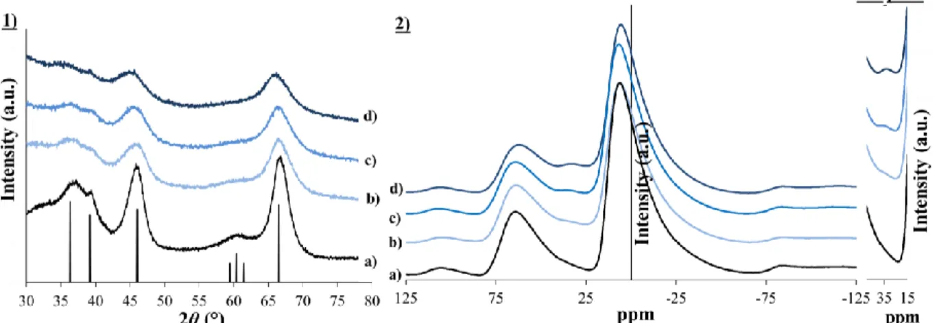
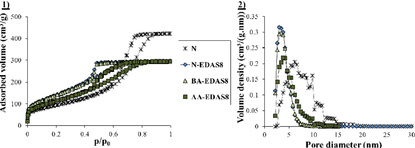
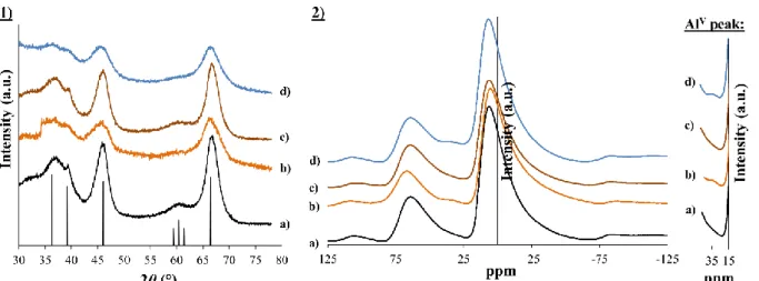
(non-fonctionnalisés ou (non-fonctionnalisés avec d’autres chaînes que celle présente dans l’EDAS) mettent en évidence le fait que la réactivité du précurseur de silice influence la cristallinité du support. La présence d’une chaîne fonctionnalisée modifie quant à elle la forme des cristallites d’alumine, menant ainsi à une distribution de taille de mésopores plus étroite et centrée à 4 nm et une plus grande surface spécifique du support.
Afin de déterminer quel type de catalyseurs synthétiser (primaires ou secondaires), le reformage catalytique de 8000 ppmv de toluène en conditions primaires (T = 750-850 °C) est effectué avec des supports constitués de γ-Al2O3 ou d’olivine, dopés avec 2 % Ni ou 10 % Fe. L’olivine, catalyseur
primaire de référence, présente de meilleurs résultats pour le reformage du toluène. Dans le cas de
γ-Al2O3, le faible dopage en Ni conduit à la formation d’un spinelle NiAl2O4 difficile à réduire, et
le dopage avec Fe favorise la transition de phase de γ-Al2O3 vers -Al2O3. Les travaux suivants sont
donc axés sur le développement de catalyseurs de type 10 % Ni/γ-Al2O3 testés en conditions
secondaires.
La réduction de catalyseurs constitués d’une unique phase de NiAl2O4 ne s’initie qu’à partir de
T = 680 °C lors de mesures en température programmée sous H2 (TPR). Cependant, ceux-ci sont
réduits lors du reformage catalytique de 24.000 ppmv de toluène à T = 650 °C. Il est démontré que dans ces conditions, le toluène est un meilleur agent réducteur que H2 ou CO, et que la réduction
des espèces NiAl2O4 par le toluène permet de convertir celui-ci en syngas tout en prévenant la
formation de coke. Lors de la présence de NiO réduit à plus basse température (T ~ 450 °C), le catalyseur ne tire pas avantage du phénomène de réduction spécial des oxydes métalliques par le toluène, ce qui entraîne ainsi la désactivation rapide du catalyseur par cokage.
L’ajout d’un surfactant (acide stéarique) lors de la préparation par voie sol-gel aqueuse s’avère efficace afin de modifier la morphologie (mésopores, macropores) de catalyseurs Ni/γ-Al2O3.
Malgré une activité catalytique nettement plus élevée, attribuée à une meilleure diffusion des réactifs, l’échantillon montre des tendances beaucoup plus importantes à se désactiver par cokage. On émet l’hypothèse que cette faiblesse est due à une combinaison de plusieurs faits: déséquilibre entre la réaction de cracking du toluène et les réactions de dissociation-migration des espèces HO* et O* + meilleure réductibilité empêchant de tirer avantage du phénomène de réduction spécial par le toluène + présence de larges pores ne restreignant pas la croissance de carbone filamentaire.
Un large screening de catalyseurs 10 % Ni/γ-Al2O3 dopés avec des métaux (Cu, Mn, Fe, Mo ou
Mn) ou des oxydes (CaO, K2O, MgO ou CeO2) est effectué. Les échantillons contenant les éléments
Mn, Mo, Ca ou K s’avèrent les plus intéressants de par leur activité catalytique et leur résistance au cokage. Pour une même quantité massique ajoutée, les échantillons constitués d’associations de dopants (Co+Mo, Mn+Mo, Ca+K ou Ce+K) affichent de meilleures performances catalytiques que ceux effectués avec un seul dopant.
Les résultats obtenus avec les meilleurs catalyseurs lors de tests catalytiques de longue durée (30 h) ou en présence de H2S sont prometteurs. Ceci porte à croire que ces catalyseurs pourraient
Summary
The gasification of biomass into bio-syngas (CO+H2) usually goes along with the formation of
tars (toluene, naphthalene) which can cause technical problems at the outlet of the reactor. The reforming of these tars via primary catalysts (inside the reactor) or secondary catalysts (outside the reactor) currently appears as the most interesting way from practical and economical point of views. The use of catalysts made of metallic nanoparticles deposited on γ-Al2O3 is an efficient
combination for tar reforming applications. During this project, an aqueous sol-gel method for the synthesis of γ-Al2O3 supports is developed. In the aim of developing catalysts with metallic
nanoparticles finely dispersed, supports of γ-Al2O3 are modified with a functionalized silicon
precursor (3-(2-aminoethylamino)propyltrimethoxysilane, EDAS). The addition of EDAS modifies the properties of γ-Al2O3. Samples prepared with other silicon precursors (non-functionalized or
functionalized with other chains than the ones of EDAS) highlight that the reactivity of the precursor influences the crystallinity of the support. The presence of a functionalized chain modifies the shape of the crystallites, which leads to a narrower pore size distribution centered on 4 nm and to a higher specific surface area of the support.
In order to orientate the project towards the development of either primary or secondary catalysts, catalytic tests are performed with 8000 ppmv of toluene under primary conditions (T = 750-850 °C) with either γ-Al2O3 or olivine supports, doped with either 2 wt. % Ni or 10 wt. % Fe.
The olivine, known as primary catalyst of reference, shows better performances. In the case of γ-Al2O3, the low loading of Ni leads to the formation of a spinel of NiAl2O4 which shows low
reducibility, and the doping with Fe favors the γ-Al2O3 to -Al2O3 phase transition of the support.
Therefore, the next studies focuse on the development of 10 wt. % Ni/γ-Al2O3 catalysts tested in
secondary conditions.
The reduction of catalysts entirely composed of NiAl2O4 only starts at T = 680 °C during H2-
TPR measurements. However, these samples are reduced during the catalytic reforming of 24.000 ppmv of toluene at T = 650 °C. It is demonstrated that under these conditions, toluene is a better reducing agent than H2 or CO, and that the reduction of NiAl2O4 oxide with toluene enables its
conversion with a very little formation of coke. For bulk NiO, reduced at low temperatures (T ~ 450 °C), the catalyst does not take advantage of the anti-coking effect brought by the phenomenon of special reduction by toluene, which leads to a quick deactivation of the catalyst by formation of carbon deposit.
The addition of a surfactant (stearic acid) during the aqueous sol-gel synthesis efficiently modifies the morphology (mesopores, macropores) of Ni/γ-Al2O3 catalysts. Despite a much higher
catalytic activity, attributed to a better diffusion of the gaseous reagents, the sample shows a much higher sensibility towards deactivation by coking. It is hypothesized that this weakness is the consequence of the combination of several facts: loss of balance between the reaction rates of toluene cracking and the rates of dissociation-migration of the HO* and O* species + better reducibility of the catalyst, which avoids the phenomenon of special reduction by toluene + presence of large pores, which do not prevent the growth of filamentous carbon.
A vast screening of catalysts composed of 10 % Ni/γ-Al2O3 and doped with metals (Cu, Mn,
Fe, Mo or Mn) or oxides (CaO, K2O, MgO or CeO2) is performed. The samples doped with Mn,
Mo, Ca ou K show the most interesting catalytic activities and resistances against coking. It is to notice that, for an identical amount, the samples doped with two different elements (Co+Mo, Mn+Mo, Ca+K or Ce+K) show better catalytic performances compared to those doped with only one type of dopant.
The tests of the best catalysts in long-term conditions (30 h) or in presence of H2S are promising.
Table of contents
Chapter I
Biomass gasification technology and its tar reforming catalysts 5
I.1. INTRODUCTION 6
I.2. BIOMASS VALORIZATION PROCESSES 7
I.2.1. Overview of the different technologies 7
I.2.1.1. Physico-chemical transformations 8
I.2.1.2. Thermo-chemical transformations 8
I.2.2. Gasification processes 9
I.2.2.1. Gasification reactions 9
I.2.2.2. Syngas empowering 11
I.3. TECHNOLOGICAL ASPECTS OF BIOMASS GASIFICATION 11
I.3.1. Overview of the processes implied in the fabrication and purification of
bio-syngas 11
I.3.2. Types of gasifier reactors 12
I.3.3. Gasification products 13
I.3.3.1. General composition of gas at the outlet of gasifiers 13
I.3.3.2. Undesirable gasification compounds 14
I.3.3.2.1. Tars 14
I.3.3.2.2. Other contaminants 15
I.3.4. Influences of experimental parameters 15
I.4. CATALYTIC PURIFICATION OF BIO-SYNGAS 16
I.4.1. Tar reforming 16
I.4.1.1. Catalytic reforming mechanisms 16
I.4.1.2. Kinetic approach 16
I.4.2. Influences of operating parameters on the catalyst performances 18
I.4.2.1. Influences of the temperature 18
I.4.2.2. Influences of the gas composition 18
I.4.2.3. Influences of the space velocity 19
I.4.3. Deactivation and regeneration of catalysts 19
I.4.3.1. Mechanisms of coking 19
I.4.3.1.1. Mechanisms of carbon deposition 20
I.4.3.1.2. Reduction of coking by adjustment of parameters 21
I.4.3.1.3. Regeneration of carbon deactivated catalysts 22
I.4.3.2. Poisoning of metallic active sites 22
I.4.3.2.1. Sulfide compounds 22
I.4.3.2.2. Poisoning with salts 24
I.4.3.3. Thermal degradation 24
I.4.3.3.2. Phase transformation 25
I.4.3.3.3. Volatilization 25
I.4.4. Catalysts developed for the bio-syngas purification 25
I.4.4.1. Influences of porous structure and shaping of catalysts 27
I.4.4.2. Influences of support composition 27
I.4.4.2.1. Carbon supports 27
I.4.4.2.2. Basic supports 28
I.4.4.2.3. Acid supports 30
I.4.4.2.4. γ-Al2O3 promoted supports 31
I.4.4.3. Influences of the composition of the metallic active sites 33
I.4.4.3.1. General trends 33
I.4.4.3.2. Noble metal-based catalysts 34
I.4.4.3.3. Ni-based catalysts 35
I.4.4.4. Influences of the dispersion of the active sites 37
I.4.4.5. Influences of the synthesis method the catalysts 37
I.5. CONCLUSIONS 38
Chapter II
Elaboration of an aqueous sol-gel method for the synthesis of γ-Al2O3 supports 40
II.1. INTRODUCTION 41
II.1.1. The sol-gel chemistry 41
II.1.1.1. Organic path 42
II.1.1.2. Aqueous path 43
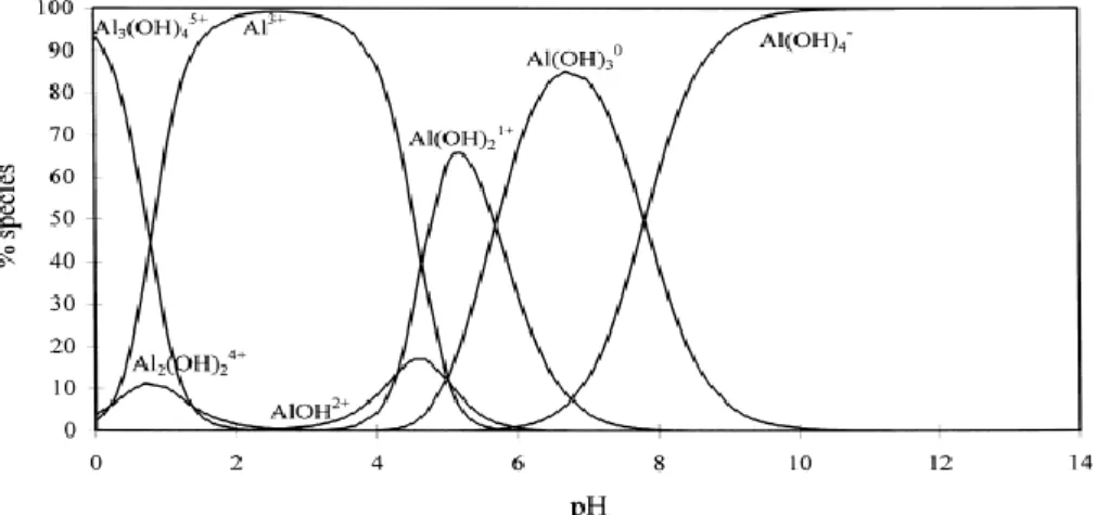
II.1.2. Formation of aluminum hydroxides and calcined alumina 44
II.1.3. Cogelation and coprecipitation methods 46
II.2. EXPERIMENTAL 47
II.2.1. Preparation of samples 47
II.2.2. Characterization techniques 48
II.3. RESULTS 49
II.4. DISCUSSION 53
II.4.1. Influences of the aluminum precursor type on the textural properties of
γ-Al2O3 supports 53
II.4.2. Modifications of the properties of γ-Al2O3 supports caused by EDAS 54
II.5. CONCLUSIONS 55
Chapter III
Influences of the aqueous synthesis way and of the organosilane nature on the
physico-chemical properties of alumina supports 57
III.1. INTRODUCTION 58
III.1.2. Thermal stabilization of γ-Al2O3 by silica addition 59
III.2. EXPERIMENTAL 60
III.2.1. General parameters 60
III.2.2. Synthesis procedures 60
III.2.2.1. Classic preparation method 60
III.2.2.2. Modifications of the Classic method 61
III.2.3. Additional calcination and steaming treatments 61
III.2.4. Characterization techniques 61
III.3.RESULTS AND DISCUSSION 62
III.3.1. Formation, composition and morphology of Al2O3-SiO2 materials 62
III.3.1.1. Precipitation curves 62
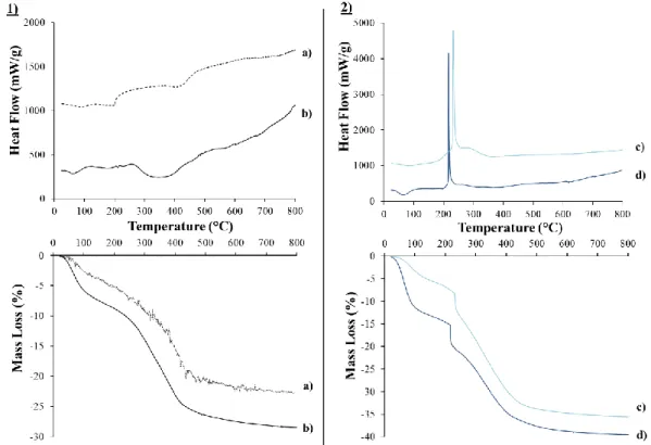
III.3.1.2. Thermal behaviors 63
III.3.1.3. Compositions of samples 64
III.3.1.4. Morphology of the supports 65
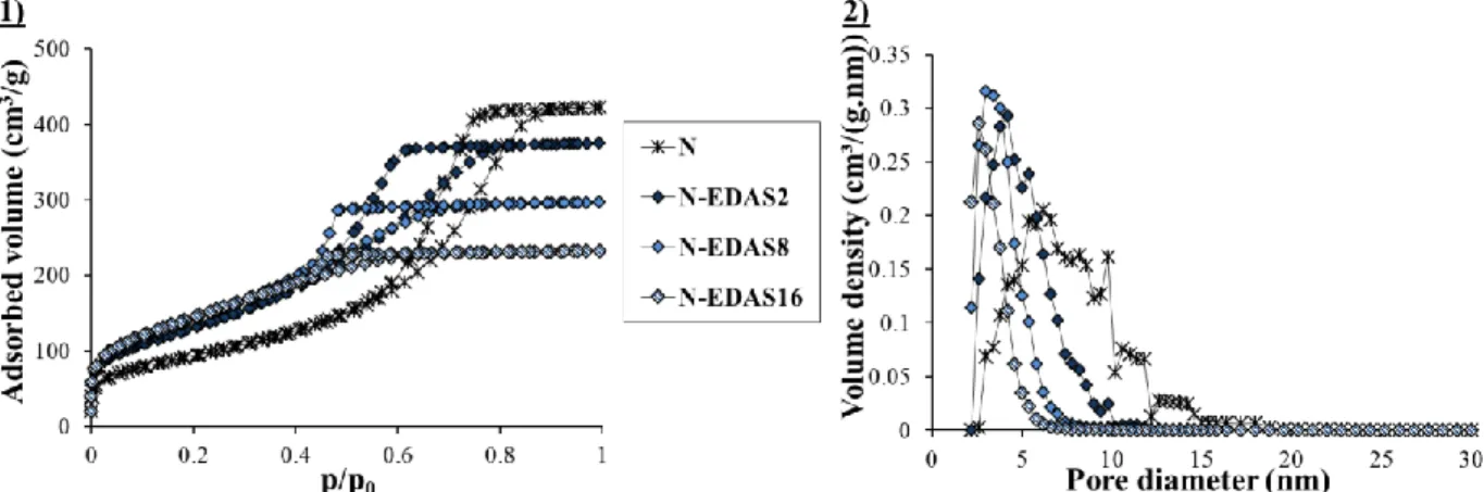
III.3.2. Effect of EDAS concentration on Al2O3-SiO2 materials 66
III.3.3. Influences of the addition step of EDAS on Al2O3-SiO2 materials 68
III.3.4. Influences of the silicon alkoxide reactivity on Al2O3-SiO2 materials 70
III.3.5. Influences of the length and composition of the silicon alkoxide functional
chain on the properties of Al2O3-SiO2 materials 72
III.3.6. External surface area of the crystallites 75
III.3.7. Evolution of physico-chemical properties of the supports with additional
thermal and steaming treatments 76
III.4. CONCLUSIONS 78
Chapter IV
Performances of nickel and iron doped materials used as primary catalysts 81
IV.1. INTRODUCTION 82
IV.2. EXPERIMENTAL 83
IV.2.1. Catalysts preparation 83
IV.2.1. Sol-gel synthesis of Ni- and Fe/γ-Al2O3 catalysts 83
IV.2.2. Impregnation of olivine with Ni and Fe 84
IV.2.2. Characterization techniques 84
IV.2.3. Catalytic experiments 85
IV.2.4. Use of toluene as tar model compound 86
IV.3. RESULTS AND DISCUSSIONS 87
IV.3.1. Characterizations of catalysts 87
IV.3.1.1. Compositions of samples 87
IV.3.1.2. Textural and physico-chemical properties of samples 88
IV.3.2. Catalytic activities and post-test characterizations 93
IV.3.2.1. Catalytic performances at T = 750 °C 93
IV.4. CONCLUSIONS 100 Chapter V
Development of Ni-based secondary catalysts supported on γ-Al2O3 103
V.1. INTRODUCTION 104
V.2. EXPERIMENTAL 106
V.2.1. Synthesis of Ni/γ-Al2O3 catalysts 106
V.2.1.1. Ni/γ-Al2O3 catalysts prepared by sol-gel method 106
V.2.1.2. Ni/γ-Al2O3 catalysts prepared by impregnation method 106
V.2.2. Characterization techniques 107
V.2.3. Catalytic tests 107
V.3. RESULTS AND DISCUSSION 109
V.3.1. Compositions of Ni/γ-Al2O3 catalysts 109
V.3.2. Influences of the catalysts preparation method 109
V.3.2.1. Properties of Ni/γ-Al2O3 catalysts prepared by impregnation or by
sol-gel methods 109
V.3.2.2. Catalytic performances of Ni/γ-Al2O3 catalysts prepared by impregnation
or by sol-gel methods 111
V.3.3. Influences of the syngas composition 113
V.3.4. Influences of the nickel loading 117
V.3.4.1. Properties of Ni/γ-Al2O3 catalysts with different Ni loadings 117
V.3.4.2. Catalytic performances of Ni/γ-Al2O3 catalysts with different Ni loadings 119
V.3.5. Influences of the temperature on the catalytic performances 122
V.4. CONCLUSIONS 125
Chapter VI
Influence of the support texture on the performances of 10 wt. % Ni/γ-Al2O3 catalyst 128
VI.1. INTRODUCTION 129
VI.2. EXPERIMENTAL 129
VI.2.1. Synthesis of Ni/γ-Al2O3 catalysts modified with stearic acid 129
VI.2.2. Characterization techniques 130
VI.2.3. Catalytic tests 131
VI.3. RESULTS AND DISCUSSION 131
VI.3.1. Compositions 131
VI.3.2. Influences of synthesis method on 10 wt. % Ni/γ-Al2O3 catalysts tailored with
stearic acid 131
VI.3.3. Further characterizations and catalytic performances of the most promising
Ni/γ-Al2O3 sample synthesized with stearic acid 136
VI.3.2.2.1. Textural properties of sample N-10Ni-PS-eth 136
VI.3.2.2.1. Catalytic performances of sample N-10Ni-PS-eth 137
Chapter VII
Enhancement of the catalytic performances and lifetime of nickel/alumina catalysts
via addition and combination of dopants 142
VII.1. INTRODUCTION 143
VII.2. EXPERIMENTAL 145
VII.2.1. Synthesis of doped Ni/γ-Al2O3 catalysts 145
VII.2.2. Characterization techniques 145
VII.2.3. Catalytic experiments 146
VII.3. RESULTS AND DISCUSSION 147
VII.3.1. γ-Al2O3 supports doped as reference materials 147
VII.3.2. Catalysts doped with 2 wt. % of metal or 1.5 wt. % of oxide 147
VII.3.2.1. Composition and textural properties 147
VII.3.2.2. Doping with 2 wt. % of metal 148
VII.3.2.2.1. Properties of Ni/γ-Al2O3 catalysts doped with 2 wt. % of metal 148
VII.3.2.2.2. Catalytic performances of Ni/γ-Al2O3 catalysts doped with
2 wt. % of metal 150
VII.3.2.3. Doping with 1.5 wt. % of oxide 153
VII.3.2.3.1. Properties of Ni/γ-Al2O3 catalysts doped with 1.5 wt. % of oxide 153
VII.3.2.3.2. Catalytic performances of Ni/γ-Al2O3 catalysts doped with
1.5 wt. % of oxide 155
VII.3.3. Double doping and synergistic effects 158
VII.3.3.1. Catalysts doped with two different metals 158
VII.3.3.1.1. General trends 158
VII.3.3.1.2. Properties of samples doped with Co+Mo or Mn+Mo 159
VII.3.3.1.3. Catalytic performances of samples doped with Co+Mo or Mn+Mo 161
VII.3.3.2. Catalyst catalysts doped with two oxides 162
VII.3.3.2.1. General trends 162
VII.3.3.2.2. Properties of samples doped with Ca+K or Ce+K 163
VII.3.3.2.3. Catalytic performances of samples doped with Ca+K or Ce+K 164
VII.3.4. Influences of dopant loadings 165
VII.3.4.1. Catalysts doped with Mn or Mo 166
VII.3.4.1.1. Properties of 10 wt. % Ni/γ-Al2O3 catalysts doped with
4 wt. % of Mn or Mo 166
VII.3.4.1.2. Catalytic performances of 10 wt. % Ni/γ-Al2O3 catalysts doped
with 4 wt. % of Mn or Mo 167
VII.3.4.2. Catalysts doped with Ca or K 168
VII.3.4.2.1. Properties of 10 wt. % Ni/γ-Al2O3 catalysts doped with
3 wt. % of Ca or K 168
VII.3.4.2.2. Catalytic performances of 10 wt. % Ni/γ-Al2O3 catalysts doped with
3 wt. % of Ca or K 169
VII.3.5. Catalytic performances of the most promising catalysts at different temperatures
VII.3.5.1. Evolution of the performances of the best Ni/γ-Al2O3 catalysts promoted
with metal dopants 171
VII.3.5.2. Evolution of the performances of the best Ni/γ-Al2O3 catalysts promoted
with oxide dopants 175
VII.4. CONCLUSIONS 179
Chapter VIII
Catalytic performances of the most promising Ni/γ-Al2O3 catalysts during long-term
tests and in presence of H2S 183
VIII.1. INTRODUCTION 184
VIII.2. EXPERIMENTAL 185
VIII.2.1. Ni-based catalysts selected 185
VIII.2.2. Characterization techniques 185
VIII.2.3. Catalytic tests 185
VIII.3. RESULTS AND DISCUSSION 186
VIII.3.1. Characterization of the commercial catalyst 186
VIII.3.2. Long-term tests 188
VIII.3.3. Catalytic performances in sulphidic conditions 191
VIII.4. CONCLUSIONS 193
General conclusions and perspectives 196
ANNEXES A.1
Annex 1:
Additional information relative to Chapter I A.2
Annex 2:
Formulae, characterization techniques, calculations, amount of reagents and A.8
X-Ray references Annex 3:
Experimental installation used for catalytic tests A.20
Annex 4:
Additional information relative to Chapter VII A.23
Annex 5:
Complementary study about the optimization of operating variables for the synthesis of
γ-Al2O3 based catalysts A.26
Annex 6:
Complementary study about 10 wt. % Ni/γ-Al2O3 catalysts modified with different
silicon precursors A.33
Annex 7:
Complementary study about the coating of honeycomb cordierite support with
Ni/boehmite gels A.42
1
Structure of the thesis
The goal of this thesis is to develop for the first time in the Department of Chemical Engineering-Nanomaterials, Catalysis and Electrochemistry of the University of Liège, heterogeneous nickel-based alumina catalysts for the reforming of tars during the gasification of the biomass.
Chapter I presents the processes involved during the gasification of the biomass and the catalytic purification of the bio-syngas. More than an introduction, this study is essential in order to target the needs of the industry, to understand the functioning of the tar reforming catalysts and to determine the conditions of the catalytic tests.
Chapter II details the development of an aqueous sol-gel method for the synthesis of γ-Al2O3 supports. The first aim of this chapter is to determine the influences of two different
aluminum precursors (Al(NO3)3 or Al-sec-butoxide) and of the synthesis operating variables
(pH, calcination temperature …) on the textural and crystallographic properties of Al2O3
supports. In order to use these alumina materials as catalytic supports, only the formation of
γ-Al2O3 is aimed, because it presents high specific surface area and pore volume values. The
second aim of this chapter concerns the synthesis of γ-Al2O3 with the addition of a
functionalized silicon precursor, 3-(2-aminoethylamino)propyltrimethoxysilane, called EDAS. By the presence of an ethylenediamine group in this molecule, it is possible to chelate metallic ions and to highly increase their dispersion at a molecular level, which is an asset for catalytic applications.
Chapter III aims at getting a better understanding about how silicon precursors modify
the final properties of γ-Al2O3 supports. It highlights the influences of the amount and of the
step of addition of the EDAS molecules during the synthesis. Furthermore, in this chapter,
γ-Al2O3 supports are synthesized with non-functionalized silicon precursors of different reactivity
(tetraethoxysilane or tetramethoxysilane) and with silicon precursors containing other functional chains than the ones of EDAS, such as 3-aminopropyltrimethoxysilane, trimethoxypropylsilane or trimethoxyoctylsilane. The aim is to understand the influences of the reactivity of the silicon precursor and the presence of functional chains on the final
properties of γ-Al2O3-SiO2 supports. Additional treatments at high temperatures (T =
600/1000/1200 °C) or under steam conditions (T = 700 °C, 10 vol. % H2O) show how the
properties of pure γ-Al2O3 supports and of γ-Al2O3 supports modified with a silicon precursor
evolve under conditions similar to the ones encountered during catalytic tests .
Chapter IV presents catalytic tests performed under primary catalytic conditions (T = 750-850 °C) with 8000 ppmv of toluene. The catalysts are either constituted of γ-Al2O3 or
Structure of the thesis
2 whether to orientate the thesis towards the development of primary (inside the gasifier) or secondary (outside the gasifier) catalysts.
Chapter V describes the catalytic performances of Ni/γ-Al2O3 catalysts tested under
secondary conditions (T = 650 °C) with 24.000 ppmv of toluene. The chapter details how the preparation method (sol-gel or impregnation) and the loading of Ni influence the formation of
nickel oxides with different interactions with the alumina support (NiO, NiO/Al2O3 or
NiAl2O4). Catalytic tests show the decisive influences of the presence of NiO or NiAl2O4 on the
performances of the catalysts. This chapter also presents catalytic tests performed with different compositions of syngas, thus in order to understand why the catalysts are reduced at lower temperatures during catalytic tests (T = 650 °C) than during TPR measurements (T = 680 °C).
Finally, the catalytic performances of quartz, pure γ-Al2O3 and 10 wt. % Ni/γ-Al2O3 samples
are also evaluated at T = 900→600 °C, in order to compare their kinetic parameters with the literature and to determine the influences of a pre-reduction step.
Chapter VI presents the synthesis of Ni/γ-Al2O3 catalysts prepared with stearic acid by
aqueous sol-gel methods. The influences of different synthesis operating parameters (type of solvent, addition step of surfactant) on the morphology of the catalysts are studied. The most
promising Ni/γ-Al2O3 catalyst modified with stearic acid is tested for the reforming of 24.000
ppmv of toluene at T = 650 °C.
The purpose of Chapter VII is to highlight which dopants and combinations of dopants
increase the catalytic activity and the resistance against coking of 10 wt. % Ni/γ-Al2O3 catalysts
tested for the reforming of 24.000 ppmv toluene at T = 650 °C. The most promising catalysts are also tested at T = 900→600 °C in order to determine their kinetic parameters and their resistance against several deactivation phenomena (coking, sintering, phase transformation).
In order to be as close as possible to real conditions of industrial biomass gasification processes, Chapter VIII studies the catalytic performances of the most promising catalysts
during long-term tests (30 h) or in the presence of H2S. The catalysts developed in this thesis
are also compared to the commercial catalyst Hifuel.
Being aware that numerous samples are synthesized, characterized and tested in the body of the manuscript, a part of the results is set in annexes. Annexes 1, 2, 3, 4 and 5 are information directly linked to the studies presented in the body of the manuscript. Annexes 6 and 7 are complementary studies relative to this thesis.
Annex 1 is complementary to Chapter I. It gives additional economic and technical information relative to the gasification of biomass.
Annex 2 reminds the formulae used in this work, gives details about all characterization techniques, shows some calculations, lists the amounts of reagents used for the synthesis of catalysts and gives the references of all the compounds determined by X-Ray analysis.
Structure of the thesis
3 One important objective of this project was to build-up an experimental installation able to recreate the conditions during biomass gasification (temperature, gas composition). Annex 3 gives details about the assembly and the functioning of this experimental installation.
Annex 4 is complementary to Chapter VII. It gives information about a new drying method used to prepare homogeneous catalysts doped with two different oxides. It also presents
the characterizations of the reference γ-Al2O3 supports doped with metals or Ce.
The aqueous sol-gel method used for the preparation of catalysts is improved throughout the project. Annex 5 presents the optimization of the operating variables used for the synthesis of γ-Al2O3 based catalysts.
Annex 6 is a complementary study inspired by the results obtained in Chapter III. This
annex studies the properties and catalytic performances of 10 wt. % Ni/γ-Al2O3 catalysts
modified with different type of silicon precursors.
The prices of sol-gel procedures being much higher than those of classic impregnation, and the project being focused on the design of catalysts for secondary catalytic applications, the development of an efficient coating method appears essential for the future utilization of the catalysts at large scale. In this way, Annex 7 sets the bases of a procedure for the coating of Ni/boehmite gel on a commercial honeycomb cordierite.
Chapter I corresponds to a review published in the journal Energy & Fuels (V. Claude, C. Courson, M. Köhler and S.D. Lambert, “Overview and essentials of biomass gasification technologies and their catalytic cleaning methods”, Energy & Fuels, (2016), vol. 30, n° 11, p. 8791-8814).
Chapter III corresponds to an article published in the journal European Journal of Inorganic Chemistry (V. Claude, M. Vilaseca, A.S. Tatton, C. Damblon and S.D. Lambert, “Influence of the method of aqueous synthesis and the nature of the silicon precursor on the physicochemical properties of porous Alumina”, Eur. J. Inorg. Chem., (2016), p.1678-1689).
The results from Chapters VII and VIII were presented during an oral communication
carried out at the 11th Natural Gas Conversion Symposium, June 2016, Tromsø, Norway.
A part of the results presented in Chapter VI and in Annex 7 were obtained during the management of the Master’s thesis of Timothée Lohay (academic year 2015-2016), whose report is entitled: “Synthesis, characterization and shaping of alumina-based catalysts for toluene reforming”.
5
Chapter I
Biomass gasification technology and its tar
reforming catalysts
Positioning of the biomass gasification technologies among the other
bio-energies;
Description and influences of the different processes involved during the
biomass gasification;
Functioning, properties and factors influencing the performances and
lifespan of tar reforming catalysts;
Review of the most common catalysts used for the production of a clean
bio-syngas.
Chapter I: Biomass gasification technology and its tar reforming catalysts
6 This chapter aims at first at presenting the basis of biomass gasification technology and positioning them among other bio-energies.
Obtaining a tar free bio-syngas from biomass gasification processes has been the subject of many studies in the last two decades, and it still remains a major technologic and economic challenge. Though the bio-syngas quality improvement can be obtained through different operating processes (reactor design, gasifying ratio, feedstock, temperature and space ratio), the purification of the bio-syngas by the use of catalysts has proved to be one of the most convenient and efficient way to eliminate undesirable tars.
In this way, after setting the essential details relative to the gasification of biomass (temperature, composition of bio-syngas, type and amount of tars and other pollutants), the rest of this chapter mostly focuses on the processes and mechanisms involved during the catalytic reforming of bio-syngas tars. Furthermore, this chapter also makes an inventory of the numerous studies conducted in order to understand the influences of different properties, especially support and active site compositions, on the tar reforming activity and on the lifetime of the catalysts.
I.1. INTRODUCTION
Adapted from old coal gasification technologies developed during the industrial revolution, the biomass gasification appears nowadays as an interesting and versatile way to take advantage of different sources (e.g. agricultural and urban wastes, energy crops, food and industrial processing residues). If managed conscientiously, these processes can therefore lead to the sustainable and renewable production of a bio-syngas, which can either be used directly as combustible or converted into storable and high valuable chemical compounds such as
methanol.[1], [2] However, despite the fact that bio-syngas is predicted to be an economically
viable energy and that some industrial plants are already in action, bio-syngas technologies still
encounter some technical problems, which seriously hinder their commercial development.[3],
[4] In this way, the tar presence at the gasifier outlet, which results from the incomplete
degradation of aromatic rings contained in the biomass, still remains a major problem that the industry has to face. Modifications of the gasifier reactor design and of the gasification operating conditions (temperature, space ratio, gasifying reagent) have proved to substantially
reduce the tar concentration.[5]–[9] Furthermore, the catalytic reforming of tars at the inside or at
the outside of the gasifier reactors also appears as a convenient and economical solution to obtain a clean bio-syngas, which explains the numerous studies conducted during the last two decades on this topic. The catalytic tar reforming has been carried out with numerous types of catalysts, the researchers modifying several aspects such as the acido-basicity, the texture, the crystallinity or the elementary composition of the supports and active sites. Furthermore, catalytic operating conditions such as the temperature, space ratio or gas mixture also proved to be of significant importance for the sustainability and performances of the catalysts.
Chapter I: Biomass gasification technology and its tar reforming catalysts
7 The first part of this chapter aims at situating the biomass gasification processes among other biomass derived technologies. Thereafter, the economic and technical advantages as well as the drawbacks of different gasifier reactors and operating conditions are described. Finally, among the several existing syngas cleaning operations, this chapter emphasizes the basic notions and recent progresses achieved in the catalytic tar reforming field.
I.2. BIOMASS VALORIZATION PROCESSES I.2.1. Overview of the different technologies
The term “biomass” covers the raw (wood, energy crops, agricultural residues …) or processed (effluents, food processing residues, green wastes …) organic matter, which can
either be of vegetal or animal origin.[10], [11] Depending strongly on its origins, biomass materials
are generally composed of cellulose, hemicellulose, lignin, lipids, proteins, simple sugars and starches. In the case of woody biomass, cellulose, hemicellulose and lignin are the three main constituents.[11] The renewable aspect that is attributed to biomass can be explained by the carbon cycle: the carbon dioxide emitted during its use is compensated by the carbon stock accumulated during its growing stage. Therefore, the biomass can only be considered as a clean
and renewable energy if obtained in a sustainable way. In case of CO2 emission not
compensated by its natural growth (for example an overexploited forest), the biomass cannot
and must not be considered as a clean and renewable energy.[10] The term “bio-energies” refers
to all the processes (industrial or not) which can produce energy from biomass. Figure A1.1 presented in Annex 1 gives a general view of the part of bio-energy in the worldwide energy
consumption in 2013.[12]
Despite the fact that the energy production from biomass becomes more interesting in developed countries, its actual part in the total global energy consumption is still very low (~3.3 %). In this way, in the European Union, the “bio-electricity” (issued from solid or liquid biomass, biogas or wastes) has generated 121 TWh in 2010, which corresponds to 3.6 % of the total electric production of the E.U..[13] According to a report from the International Energy Agency (IEA), the part of bio-electricity has been growing at an average rate of 2.5 % per year
over the 2000-2010 decade.[11] From an economical aspect, the supplying costs can be low,
when agricultural or urban residues are collected and transported over short distances. However,
expenses can quickly arise when raw materials are imported (ex: wood pellets).[14] Following
these observations, the biomass valorization sector is more inclined to develop itself into small interconnected installations, rather than huge centralized complexes. Biomass can be converted into energy or by-products via versatile transformation technologies: Figure I.1 gives an overview of the principal processes. Basically, two different operations of biomass transformation are performed: physico-chemical or thermo-chemical.
Chapter I: Biomass gasification technology and its tar reforming catalysts
8 Figure I.1: Overview of main biomass valorizations, inspired from the literature.[2]
According to a study made by the International Renewable Agency, IRENA, biomass gasification technologies can provide power with relatively low costs compared to other
renewable resources (such as bio-diesel) (Figure A1.2 presented in Annex 1).[15], [16] A study
made by the International Energy Agency, IEA, showed a cost estimate for different fuels: gasoline from petroleum, conventional and advanced biodiesel, bio-synthetic gas and ethanol
from different sources (Figure A1.3 presented in Annex 1).[15] Despite the conventional gasoline
price being predicted to increase, some renewable solutions, such as conventional or advanced bio-diesel, do not seem to be economically interesting alternatives. In comparison, bio-synthetic gas obtained from gasification was on the third position below ethanol, which means that bio-syngas could really be an efficient alternative.
I.2.1.1. Physico-chemical transformations
Three main technologies of physicochemical transformations can be distinguished: oil extraction, fermentation and anaerobic digestion. Details about these processes are given in part I of Annex 1.
I.2.1.2. Thermo-chemical transformations
Though less developed, the thermo-chemical processes are generally more efficient than the physico-chemical ones. The reasons are as follows: 1) a shorter reaction time (a few seconds or minutes for thermo-chemical processes vs. several days, weeks or even longer for bio-chemical/biological processes); 2) a higher ability to destroy most of the organic compounds. Lignin materials are typically considered to be non-fermentable and thus cannot be completely decomposed via biological processes, whereas they can be fully converted thanks to
thermo-Chapter I: Biomass gasification technology and its tar reforming catalysts
9
chemical transformations.[11] In comparison to fossil fuels, biomass has lower heating values
(LHV) for a similar weight. In fact, the heating value of biomass ranges from 15-19 GJ/t, compared to 20-30 GJ/t for coals. Furthermore, the bulk density, also known as energy density, is only 10-40 % of most fossil fuels. However, in comparison to fossil fuels, biomass contains much higher volatile matter contents (80 % in biomass instead of 20 % for fossil fuels), which means that biomass has a high ignition stability and can easily be thermo-chemically processed
towards other higher value fuels (syngas).[11] The thermo-chemical transformation processes
are summarized in Figure I.2. They can be classified into three different paths: combustion, pyrolysis and gasification processes. The main difference lies in the amount of oxygen used
during the operations, thus modifying the thermo-chemical reactions and reaction products.[10],
[17] Details about the valorization of the biomass by other thermo-chemical transformations than
gasification (combustion and pyrolysis) are given in part I of Annex 1.
Figure I.2: Scheme of the three different thermo-chemical ways.[17], [18]
I.2.2. Gasification processes
The biomass gasification is a sum of complex thermo-chemical processes, which include biomass drying, pyrolysis, char gasification and reforming of gaseous products formed by
pyrolysis.[17] Its final product is a combustible gas, called syngas or bio-syngas, which is mainly
composed of H2 and CO, and whose lower heating value (LHV) is situated between 5 and 20
MJ/Nm3 (depending on the biomass and gasification vector: air, steam or pure O2).[19] Common
gasifying agents used in industrial gasifiers include a mixture of steam and air or oxygen, with the amount of oxygen being generally 1/5 to 1/3 of the amount theoretically required for complete combustion. The necessary heat for gasification is produced by a partial combustion of the biomass in the same reaction chamber. In addition to the typical biomass products and wastes described above, it is important to note that the gasification operations can also be performed with plastics, coal or a mixture of plastics/coal/biomass, thus increasing the versatile aspect of the gasification.[20]–[24]
I.2.2.1. Gasification reactions
At temperatures between T = 800 °C and T =1200 °C, several parallel gasification reactions take place inside the gasifier (Table I.1). The produced tars are converted by further
Chapter I: Biomass gasification technology and its tar reforming catalysts
10 partial oxidation, reforming, hydrogenation and thermal cracking with highly endothermic
reaction enthalpies comprised between + 200 kJ/mol to + 300 kJ/mol(Equations I.1 - I.5). The
combustion of char and volatile compounds (CO, H2, CH4) via partial or complete oxidation
reactions occurs in the presence of air or oxygen (Equations I.6 - I.7 and Equations I.13 - I.16). These reactions are highly exothermic and allow generating the necessary heat for the drying,
pyrolysis and gasification reactions. The produced H2O and CO2 molecules are thereafter
consumed during the char gasification (Equations I.8 - I.11). Reactions of water-gas shift (Equation I.17) and methanation (Equations I.18 – I.19) take place in either direction, depending on the specific temperature, pressure and reactants concentrations. Water-gas shift
is of great importance since it plays a significant role for the generation of H2, and therefore for
the LHV of the syngas. The methanation reactions occur slowly at low temperatures and in the
absence of any catalysts.[17], [25] The Gibb’s energy for the Boudouard (Equation I.8) and
water-gas shift (Equation I.17) reactions are negative at temperatures above T = 720 °C and up to T = 820 °C, respectively.[26], [27]
Table I.1: Main reactions involved in the biomass gasification process.[25], [28], [29]
Equations Heat of reaction
(kJ/mol) at 298 K Name Equation n°
Tars general equations
Highly endothermic + (200 to 300)
Tars partial oxidation I.1
Tars dry reforming I.2
Tars steam reforming I.3
Tars hydrogenation I.4
Tars thermal cracking I.5
Char combustion
-394 Complete combustion I.6
-111 Partial combustion I.7
Char gasification
+173 Boudouard reaction I.8
+131 Water-Gas reaction 1 I.9
+16 Water-Gas reaction 2 I.10
-91 Water-Gas reaction 3 I.11
-75 Hydrogasification reaction I.12
Homogeneous volatile oxidation
-283 Carbon monoxide combustion I.13
-242 Hydrogen combustion I.14
-283 Methane combustion I.15
-35 Methane partial oxidation I.16
-41 Water-Gas Shift reaction I.17
Methanation reactions
-204 Methanation reaction 1 I.18
Chapter I: Biomass gasification technology and its tar reforming catalysts
11
I.2.2.2. Syngas empowering
Currently, most of the syngas obtained from the biomass gasification is used for the generation of power. The cogeneration method is the more current method to convert syngas into energy: thanks to a few technical adjustments, the syngas can replace gasoline or natural
gas in internal or external combustion machines normally used for electricity production.[30] At
the same time, the heat emitted during these processes is collected and used for household
heating or for additional electricity production thanks to steam turbines.[30], [31]
However, as depicted in Figure A1.4 presented in Annex 1, the bio-syngas produced can also be processed to a variety of useful compounds, mainly thanks to the Fischer-Tropsch and
methanol synthesis processes.[1], [17] The methanol, which is one of the easiest product formed
by the Fischer-Tropsch process, becomes growingly interesting since it could be a practical alternative to gasoline and diesel.[32], [33]
I.3. TECHNOLOGICAL ASPECTS OF BIOMASS GASIFICATION
I.3.1. Overview of the processes implied in the fabrication and purification of bio-syngas Seeing all the promising studies presented in the previous part, one could wander why gasification technologies are not more developed. In fact, the Achilles’ heel of gasification technology lies in its cleaning processes. Indeed, according to previous studies,[3], [4] the gas
cleaning operations for a fluidized bed make up for 65-85 % of the total costs. These cleaning costs, mainly due to the elimination of tars, are the main obstacles to the commercialization of these technologies. This explains why they are less interesting in comparison to the low costs of oil, gas and coal.[14], [34]
The global processes involved in biomass gasification are presented in Figure I.3. At first,
the biomass undergoes upstream processes such as milling and drying. Thereafter, the biomass is converted into gaseous products during the gasification step.
Figure I.3: Main processes involved in biomass gasification.[35]
The primary methods consist in modifications inside the gasification reactor, allowing
obtaining a cleaner syngas with more interesting general composition (higher LHV).[10], [35] In
theory, if the primary methods were perfect, the syngas exiting the gasifier would be tar-free, thus eliminating the need of downstream secondary methods. An optimization of the gasification can be reached through three different technical modifications: 1) it can be done by
Chapter I: Biomass gasification technology and its tar reforming catalysts
12 modifying the gasification conditions, such as temperature, pressure, gasifying medium
(air/steam/O2), residence time, and equivalence ratio (defined in Annex 1, Equation A1.1). The
selection of these parameters also depend on the type of gasifier.[10], [35] A homogeneous bed
temperature profile and a well-functioning bed fluidization are of utmost importance in case of a fluidized-bed gasifier; 2) it can be performed with the use of bed additives, also known as “primary catalysts”. These catalysts, located inside the reactor, promote the different gasification reactions via different catalytic paths, allowing obtaining a tar-free syngas with higher LHV. Furthermore, the addition of primary catalysts also prevents the agglomeration of
solid products such as slag and subsequent choking of the bed;[35] 3) the kind of reactor also
strongly influences the gasification processing parameters, resulting in an important tar
reduction and a modification of the final gas composition.[19], [36], [37]
At the gasifier outlet, the syngas usually undergoes various downstream processes in order to be purified from undesirable compounds. These processes can be divided into two categories:
1) the secondary methods, which aim at removing the remaining tars at the reactor outlet. These processes can be conducted at low temperatures and consist of mechanical methods such as the use of a cyclone, baffle filter, ceramic filter, rotating particle separator, electrostatic filter and scrubber. Although these methods are reported to be very effective, in most cases, they are
neither convenient, nor economically viable.[10], [38] Indeed, most of these operations are
performed with physical separations, which result in the problematic creation of large amounts of toxic condensates. Therefore, instead of transferring the tars into a solid/liquid phase, it is
largely preferred to destroy them by catalytic reforming methods, which takeadvantage of the
high temperatures of the exiting syngas (T = 500-700 °C). These techniques result in an increase
of efficiency and lower operational costs.[10], [19] Indeed, more than destroying the tars, using a
catalyst permits the improvement of several useful reactions such as the reverse methanation or
Water-Gas shift reactions, which allow obtaining a syngas with a high LHV.[19] Some other tar
cleaning methods, such as the use of plasma arc, could also be used but currently remain technological curiosities.[19], [39]
2) the second downstream cleaning method aims at purifying the syngas from undesirable
gaseous (mainly H2S) and solid (dusts, ashes) compounds. The elimination of H2S and other
sulfide compounds is usually done at lower temperatures (T = 150-300 °C) thanks to the
adsorption on specific metallic oxide (for example ZnO) doped ceramic filters. Once these
filters are saturated, they can undergo air regeneration.[40] The solid separation is finally done
thanks to physical methods similar to the ones presented above: cyclones, filters and scrubber.
Due to a tar-free syngas at this stage, the mechanical cleaning methods are no hindrances.[10]
I.3.2. Types of gasifier reactors
The type of reactor has a strong impact on gasification processes and on the final gas composition. In 2012, the European Biomass Industry Association made an inventory of the 50
Chapter I: Biomass gasification technology and its tar reforming catalysts
13 manufacturers identified in the U.S.A, Canada and Europe offering “commercial” gasification
plants, resulting in the following occurrence of gasifier kinds[41]:
- 75% of the designs used a downdraft fixed bed;
- 20% of the designs used fluidized bed systems (bubbling/ circulating or dual); - 2.5% of the designs used an updraft fixed bed;
- 2.5% were of other designs.
Each type of reactor has its own economic and technologic strengths and weaknesses. As a general point, air-based gasifiers are relatively cheap and typically produce a syngas with a
high N2 content, resulting in a low energy content (5-6 MJ/m3 on a dry basis). In comparison,
oxygen or steam-based gasifiers tend to produce a syngas with a high concentration of CO and
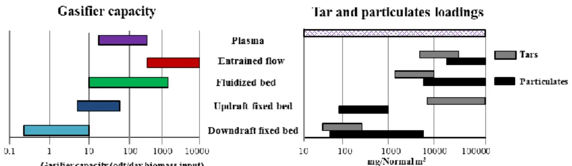
H2 resulting in a much higher energy content (9-19 MJ/m3).[14] The gasifier capacities and their
typical particulate/tar loadings (Figure I.4) are the two major technical aspects taken into account in a gasifier design.[19], [36]
Figure I.4: Technological gasifier capacity range and tars/particulate loadings, adapted from the literature.[19], [36]
Details about the main commercial and pilot gasifiers currently in activity, as well as the processes, advantages and drawbacks of each type of gasifier are given in part II of Annex 1.
I.3.3. Gasification products
I.3.3.1. General composition of gas at the outlet of gasifiers
Table I.2 presents the composition of outlet gas which can be obtained depending on the gasifying agents (air, steam or pure O2). Plasma gasifiers are also presented because their
operating parameters are different from the other gasifiers. The exiting gas compositions
depend on various operating parameters, making it unique for each installation.[19], [34], [39] The
highest H2 and CO concentrations are obtained under steam conditions, whereas the gasification
made with air (the most common for fixed-bed reactors) leads to weak CO and H2
concentrations.
Table I.2: General composition of biomass gasification syngas.[6], [34]
Gasifying agent Gas product (vol. %)
H2 CO CO2 CH4 N2 H2O
Air 5-16 10-22 9-19 2-6 42-62 11-34
Steam 38-56 17-32 13-17 7-12 0 52-60
Steam+O2 14-32 43-52 14-36 6-8 0 38-61
Chapter I: Biomass gasification technology and its tar reforming catalysts
14
I.3.3.2. Undesirable gasification compounds
I.3.3.2.1. Tars
The major issue in biomass gasification is dealing with the tar formed during the process.
Milne & Evans came up with a good definition of tar in the biomass gasification[42]: “Tar is a
complex mixture of condensable hydrocarbons, which includes single ring to multiple ring aromatic compounds along with other oxygen containing hydrocarbons and complex polycyclic aromatic hydrocarbons.”
Tars are formed during the biomass gasification by a serie of complex reactions which
depend on gasification conditions such as the gasifying reagent (air, pure O2, steam), the kind
of reactor, the temperature of the gasification, the raw material moisture and the biomass feedstock.[36], [37], [42]–[45] Elliott et al.[43] was the first to establish a scheme of the formation and
evolution of the tars composition with the temperature. Milne et al. [42] improved this scheme
and showed the influence of residential time on the tar formation. They also introduce an important concept: the tar ranking. Figure I.5 is inspired by these two major studies and
describes the different tar families as a function of temperature.[42], [43]
At low temperatures (T ~ 400 °C), primary tars, derived from the biomass decomposition through pyrolysis and gasification, are present. They are composed of molecules rich in oxygen such as alcohols, aldehydes, ketones, carboxylic acids, phenols and furans. With increasing temperatures (T > 500 °C), the primary tars further decompose into secondary tars: aromatic compounds with one ring, two rings, three rings and a small concentration of compounds with more than three rings. Gasification ranging from T = 700-900 °C produces tertiary tars, which
are polyaromatic compounds with four and five rings.[36], [44], [45]
Figure I.5: Tar ranking as a function of temperature, adapted from the literature.[36], [42], [45]
According to Coll et al.[46] (Figure I.6), the majority of the hydrocarbons present are toluene and other one ring aromatics (46 wt. %), followed by naphthalene and two ring aromatic hydrocarbons (28 wt. %).
Chapter I: Biomass gasification technology and its tar reforming catalysts
15 A study conducted by the Energy Research Center of the Netherlands (ECN), the
Toegepast Natuurwetenschappelijk Onderzoek (TNO) and the University of Twente (UT),
proposed a more elaborated classification in order to rank the multitude of unconverted tar
compounds present at the exit of a gasifier.[48] Tars were classified according to their molecular
weight, solubility and condensability. Table I.3 presents the five different classes of tars
established, their properties and representative compounds. Coll et al.[46] studied the catalytic
reforming of five typical biomass tars with two commercial catalysts (UCI G90-C and ICI 46-1), both containing about 15 wt. % of nickel on alumina. The results showed that the order of reactivity for the reforming of tars was the following: benzene > toluene >> anthracen >> pyrene > naphthalene. Therefore, according to this study, since it has the lowest reactivity, naphthalene appears to be the most adequate molecule as biomass tar model.
Table I.3: Classification of tars based on molecular weight (wt. %).[45]
Tar class Class name Property Representative compounds
1 GC-undetectable Very heavy tars
2 Heterocyclic
aromatics Highly water-soluble Pyridine, phenol
3 Light aromatic
(1 ring)
Do not pose a problem regarding condensability
and solubility Toluene, benzene
4 Light PAH (2-3 rings) Condense at low temperature, even at very low
concentrations
Naphthalene, anthracene,
fluorine, indene
5 Heavy PAH
(4-7 rings)
Condense at high temperature and very low concentration
Fluoranthene, chrysene,
coronene, pyrene I.3.3.2.2. Other contaminants
A variety of other gas contaminants may cause technical and environmental problems
(Table I.4). Nitrogen may leads to the formation of toxic compounds such as ammonia (NH3)
or cyanide (HCN). Hydrogen sulfide (H2S) is a major problem since it can provoke corrosion
of the pipes and cause acid rain if emitted into the atmosphere. This is also the case for other elements such as alkali metals or chlorine.[14], [34], [49]
Table I.4: Other contaminants than tars.[14], [49]
Contaminant NH3 (ppmv) H2S (ppmv) HCN (ppmv) Alkali metals (Na/K) Chlorine
Concentration 1000-14.000 20-200 5-500 # #
Potential
problem Emissions
Corrosion +
Emissions Emissions Corrosion
Corrosion + Emissions
#: not available
I.3.4. Influences of experimental parameters
Further information concerning the influences of the biomass feedstock, of the gasification temperature, of the gasifying reactants (equivalence ratio, steam to biomass ratio), of the gasifying pressure and of the gasification time on the final bio-syngas composition are detailed in part II of Annex 1.
![Figure I.8: Mechanisms of carbon formation, inspired from Trimm et al. [68] .](https://thumb-eu.123doks.com/thumbv2/123doknet/14558324.726273/33.892.221.680.756.1049/figure-i-mechanisms-carbon-formation-inspired-trimm-et.webp)