THÈSE DE DOCTORAT DE
L’UNIVERSITÉ PIERRE ET MARIE CURIE
Spécialité
Physique de la Particule à la Matière Condensée
Présentée par
Tolga ZENGIN
Pour obtenir le grade de
DOCTEUR de l’UNIVERSITÉ PIERRE ET MARIE CURIE
Fabrication, Characterization and Modeling of Electroactive
Polymer based Smart Structures for a Biological-like Artificial Muscle
Soutenu le 29 Novembre 2012 devant le jury composé de:
Madeleine Djabourov Professeur, E.S.P.C.I, Paris Présidente
Didier Devilliers Professeur, UPMC, Paris Examinateur
Bernard Gauthier-Manuel Chargé de recherche, HDR,
FEMTO-ST, Besançon
Rapporteur
Hyacinthe Randriamahazaka Professeur, Uni. Paris 7,
ITODYS, Paris
Rapporteur
Fréderic Cohen-Tenoudji Professeur émérite,
UPMC, Paris
Directeur de thèse
Claude Deslouis Directeur de recherche
émérite, LISE, Paris
Polymer based Smart Structures for a Biological-like Artificial Muscle
Tolga Zengin
Pierre and Marie Curie University, 2012
Advisors: Fréderic Cohen-Tenoudji and Claude Deslouis
A
BSTRACTThe objective of this thesis is the study of the problem and the realization of an electroactive biomimetic muscle with the optimization of its manufacturing, the modeling of its operation and the characterization of its performances. The artificial muscles are biologically inspired actuators having the flexibility and the adaptability which enables to imitate the biological functions for use in robotics and the energetically effective engineering applications. The Ionic Polymer Metal Composite (IPMC) constitutes a class of actuators with new properties of electromechanical coupling, and enables to convert energy between the chemical, electrical and mechanical fields. We treated in this work the specific case of an IPMC made up of a film of Nafion. The first stage of its manufacturing was to create a roughness on the surface of the membrane of Nafion to allow the deposit of platinum electrodes on both sides of film by electroless plating technique. The existing methods of sandblasting and sandpapering require several repeated cycles of fabrication in order to achieve necessary conductivity of deposited electrodes. In our research it was demonstrated that a plasma etching of Nafion membrane in a cathodic sputtering reactor was more efficient than roughening with preceding methods, allowing minimizing the amount of plating material during metallization with respect to conventional methods and with a shorter fabrication time. Varying the parameters of the plasma treatment, we could obtain electrode resistivities of minimum 1.8 Ohms/square in only one fabrication cycle. This treatment carves out well-connected structures of micro-valleys on Nafion membrane similar to that resulting from a deposit grown under DLA (Diffusion-limited aggregation) conditions.
In the work of characterization of IPMC, two new characterization methods were elaborated for obtaining Young’s modulus of cantilever-shaped bending actuators. In
the first method the force applied at the tip was zeroed, using pre-measured counter-loads which were dropped at an instant of actuation, in order to measure the instantaneous Young’s moduli. In the second method vibration modal frequency analysis of cantilever was used. Young’s Modulus around 200 MPa was obtained with both methods. These two methods do not require a force sensor. They thus allow the use of a simpler instrumentation in order to obtain this important material property. We characterized the electromechanical coupling for these IPMC samples and also carried out an impedance analysis. We proposed an equivalent electromechanical circuit for the IPMC, where the electromechanical coupling term was introduced into the capacitive term coming from the Nafion/platinum interfaces. The adjustments of the parameters of the equivalent circuit to the experiments provided a Young’s modulus value of megapascal order in agreement with the two above mentioned techniques.
The last part of the work concerned the modeling of an anthropomorphic finger with a biological-like actuation and actuated by longitudinal contractile pneumatic (Mc Kibben) muscles, for an application actuated by longitudinal contractile actuator constructed by two antagonistic IPMC actuators. The proposed actuator was modeled by modifying the nonlinear Euler-Bernoulli beam model augmented for eigencurvature proposed by Xiao et. al. for the horizontal force configuration.
intelligentes fonctionnant comme muscles artificiels biomimétiques et
fondées sur des polymères électroactifs
Tolga Zengin
Université Pierre et Marie Curie, 2012
Directeurs: Fréderic Cohen-Tenoudji et Claude Deslouis
R
ÉSUMÉL'objectif de cette thèse est l'étude de la problématique et de la réalisation d'un muscle biomimétique électroactifs avec l'optimisation de sa fabrication, la modélisation de son fonctionnement et la caractérisation de ses performances. Les muscles artificiels sont des actionneurs biologiquement inspirés ayant la flexibilité et l'adaptabilité qui permettent d'imiter les fonctions biologiques pour l'usage dans la robotique et les applications énergétiquement efficaces d'ingénierie. Les Composés Métal/Polymère Ionique (IPMC) constituent une classe d'actionneurs avec de nouvelles propriétés de couplages électromécaniques, et permettant de convertir l'énergie entre les domaines chimiques, électriques et mécaniques. On a traité dans ce travail le cas spécifique d’un IPMC constitué d’un film de Nafion. La première étape dans sa fabrication a été de créer une rugosité à la surface du gel de Nafion pour permettre le dépôt d'électrodes de platine de part et d’autre du film par une technique de dépôt sans courant. Les méthodes existantes de sablage et de traitement au papier de verre, exigent de répéter cette étape de dépôt afin d’obtenir une conductivité suffisante des électrodes déposées. Il a été montré lors de cette recherche qu'un traitement plasma de la membrane de Nafion dans un réacteur de pulvérisation cathodique était plus efficace que le dépolissage avec les méthodes précédentes, permettant de minimiser la quantité de métal déposé par rapport aux méthodes conventionnelles et avec un temps de fabrication plus court. En faisant varier les paramètres du traitement plasma, nous avons pu obtenir des résistivités d'électrode minimum de 1,8 Ohms/carrée en un seul cycle de fabrication. Ce traitement sculpte des structures bien connectées de micro-vallées sur la membrane de Nafion semblables
à celles qui résultent d'un dépôt développé dans des conditions de DLA (Agrégation limitée par diffusion).
Pendant les travaux de caractérisation des IPMC, deux nouvelles méthodes d’obtention du module d’Young des actionneurs en flexion sous la forme de poutres encastrées ont été élaborées. Dans la première méthode, la force appliquée au bout de l’actionneur était annulée, en utilisant des contrepoids pré mesurés qui ont été retirés à différents instants lors de l’actionnement, afin de mesurer les modules d'Young instantanés. Dans la deuxième méthode, la fréquence du mode de poutre fondamental de vibration a été utilisée. Un module d’Young autour de 200 MPa a été obtenu avec les deux méthodes. Ces deux méthodes n'exigent pas un capteur de force. Elles permettent ainsi l'utilisation d’une instrumentation plus simple afin d'obtenir cette propriété matérielle importante. Nous avons caractérisé le couplage électromécanique pour ces échantillons d'IPMC et également effectué l’analyse de l'impédance. Nous avons proposé un circuit électromécanique équivalent pour l’IPMC, où le terme de couplage électromécanique a été introduit dans le terme capacitif provenant des interfaces Nafion/platine. Les ajustements des paramètres du circuit équivalent aux expériences ont fourni une valeur de module d’Young de l’ordre du megapascal en accord avec les deux techniques précitées.
Le dernier volet du travail a porté sur la modélisation d'un doigt anthropomorphe proche du fonctionnement biologique, et actionné par des muscles pneumatiques contractiles longitudinaux (Mc Kibben), pour une application actionné par structure contractile longitudinale constituée de deux actionneurs IPMC antagonistes. L'actionneur proposé a été modélisé en modifiant le modèle non linéaire de faisceau d'Euler-Bernoulli augmenté pour la courbure propre proposée par Xiao et coll. pour la configuration avec force horizontale.
Acknowledgements
I can not thank enough to my advisors Mr. Frédéric Cohen Tenoudji and Mr. Claude Deslouis.
I had the luck to became one of the students of Mr. Cohen Tenoudji when Mr. Murat Boratav accepted me to the master class of (Modelisation et Instrumentation en Physique) at Pierre and Marie Curie University. I consider myself very lucky to have him as my advisor of thesis as he always shared his wisdom, support and productive discussions all through my thesis, in the hard times as well as in the easier times, and this took me to the end of this work. Without his continuous generosity, this work would never have finished.
When I had left the laboratory that I started my thesis in the search of a stable and competent research facility it was Mr. Claude Deslouis who opened the doors of his laboratory to me and became my co-advisor of thesis, adding new dimensions to this work, sharing his rich perspective and experience.
I had the chance to work with these two great professors as an apprentice researcher and I will do my best in order to achieve and transmit the quality of the approach and guiding that I saw from them during my thesis work. Their scientific level that I witnessed during this work will stay with me as a scale to measure the future experiences.
I would like to thank successive directors of the Doctoral School of Physics of UPMC, ED-389, Mme. Anne-Marie Cazabat, Professor at UPMC, who catalyzed and saw to it that I continue my thesis at LISE after ANIM and Mr. Jean Hare, Professor at UPMC who watched rigorously over the completion of my thesis.
I would like to thank Mr. François Huet, director of LISE for his support and I would like to thank to all the members of LISE, who all helped me in one way or another in some part of this work. I would like to thank to Mr. Hubert Cachet, research professor for his help on surface resistivity measurements, to Mr. Alain Pailleret, assistant professor at UPMC, for his participation to my studies on polymer synthesis and planning of my manuscript.
I am grateful for the contribution of Mr. Philippe Rousseau who is no longer with us, whom I met the first day I visited LISE with Mr. Cohen-Tenoudji in order to meet Mr. Deslouis at Ivry. Philippe provided me with various programs that he had written, in areas
varying from fractal dimension calculation to data acquisition and simulation programs used during my work.
I would like to thank Mme André Hermant, director of Comité d'Aide aux Intellectuels Réfugiés (CAEIR) association for their financial and moral support all through my thesis.
I had started my thesis at Inserm U-483 (which later became ANIM), a neuroscience laboratory. Mr. Christian Darlot, researcher at CNRS, Mr. Habib Boulekbache, professor at UPMC, Mr. Bruno Delord, assistant professor at UPMC, Mr. Stephan Genet (assistant professor at UPMC), Mr. David Montero (research engineer at CNRS), Mr. Roland Rouxel (research engineer at Inserm), Pascal David (Assistant Professor at UPMC) were always present for help, discussion, exchanging ideas and sharing their know-how.
I would like to thank my friends, Nizar Aouina, Priscilla Tamiasso-Martinhon Mai Tran, Bruno Delord, David Montero and to Salwa Elkhoussi, and Murat Verdioglu.
I would like to thank my parents Hasan Zengin and Melek Zengin, who were always by my side when I needed most, to my sister Canan Zengin and my brother Koray Zengin for their continuous strong support and love overcoming the long distances.
I thank to my daughter Evin Melek Zengin, who declared herself “fille de science” (daughter of science) in the corridors of LISE when she was 4 years old and did not ever stop asking me interesting questions since all through my thesis.
Finally I had the honor and the pleasure to present and support what I could have done during my thesis in front of the jury composed of Madeleine Djabourov Professor at E.S.P.C.I who accepted to be the president, Didier Devilliers, Professor at UPMC, Bernard Gauthier-Manuel, Researcher (HDR) at FEMTO-ST and Hyacinthe Randriamahazaka, Professor at Paris 7 University/ITODYS who accepted to be reporters and Fréderic Cohen-Tenoudji, emeritus professor at UPMC and Claude Deslouis, emeritus research professor at LISE.
I would like to thank everyone who contributed at different levels to this doctorate thesis. Without them and their invaluable help I certainly couldn’t have had the courage to finish this work.
To my mother,
Melek Zengin.
Table of contents
List of Figures
xvList of Tables
xxiiiIntroduction
xxv1. General Review: From the Biological Muscle to the
Biomimetic Actuators
1. Biological Muscle as an Actuator 1
2. Various Types of Biomimetic Actuators 4 2.1. Actuators driven by biological material 4
2.2. Mc Kibben Pneumatic Muscles 5
2.3. Shape Memory Alloys (SMAs) 6
2.4. Magneto-active and photo-active gels 7
2.5. Electro-active materials based actuators 9
2.5.1. Electroactive Ceramics 9
2.5.2. Carbon nanotubes (CNTs) 10
2.5.3. Electro-Active Polymers (EAPs) 11
2.5.3.1. Electronic EAPs 11
2.5.3.1.1. Electro-strictive polymers 11 2.5.3.1.2. Dielectric Elastomer Actuators 12
2.5.3.2. Ionic EAPs 14
2.5.3.2.1. Poly-electrolyte gels 14 2.5.3.2.2. Electronically Conducting Polymers (ECPs) 15 2.5.3.2.3. Ionic Polymer Metal Composites (IPMCs) 17
3. Ionic Polymer Metal Composites 18
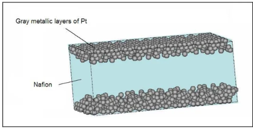
3.1. Historical Background of Ionic Polymer Actuators 19 3.2. Ion Exchange Polymers: Nafion Structure 20 3.3. Description and Actuation Mechanism 21
3.4. Relaxation Mechanism 22
3.5. Fabrication Methods of Ionic Polymer Metal Composites 22 3.6. Historical Background of Characterization 23
4. Conclusions 23
2. General Review on Modeling of IPMC
272.1. Introduction 27
2.2. Empirical (Black Box) Models 27
2.2.1. Kanno et al. (1994) 28
2.3. Physical Models 28
2.3.1. Modeling of Electric Double Layer: Bockris et al. (1963) 29
2.3.2. Tadokoro et al. (2000) 30
2.3.3. Nemat-Nasser et al. (2000) 34
2.3.4. De Gennes et al. (2000) 37
2.3.5. Comparative Explanation of IPMC Actuation Mechanisms with
Different Physical Models 39
2.4. Gray Box Macroscopic Models using Physical Laws and Empirical Parameters
2.4.1. Kanno and Tadokoro (1996) 44
2.4.2. Newbury-Leo Equivalent Circuit Model (2002) 45 2.4.3. Xiao and Bhattacharya, Nonlinear Euler Bernoulli Beam Model
Augmented for Eigencurvature (2001) 48
2.5. Discussion on Modeling of IPMC 49
References for Chapter 2 52
3. Fabrication and Morphological Characterization of IPMC
553.1. Introduction 55
3.2. Fabrication of IPMC 57
3.2.1. General Review on Fabrication methods 58
3.2.1.1. Surface roughening the membrane material 58 3.2.1.2. Membrane conditioning and fabrication of the composite structure 58 3.2.1.2.1. Membrane treatment with HCl or HNO3 58
3.2.1.2.2. Preparing the ion exchange solution containing metal salts 59 3.2.1.2.3. Reducing the metal salt cations to metallic state
under the form of nanoparticles 59
3.2.1.2.4. Developing of electrode by metal coating of surface 60
3.2.1.3. Cation Exchange 61
3.2.1.4. Number of Cycles of Fabrication 62
3.2.2.1. Fabrication Procedure 63 a. Surface Roughening of the Membrane 63
b. Ion-exchange to Platinum 63
c. Primary Plating (Reduction) 64 d. Secondary Plating (Developing) 65
e. Cation Exchange 66
3.2.2.2. Fabrication Setup 68
3.2.2.3. Fabrication Results: Form of deposited electrodes 69 3.2.3. Fabrication at LISE with Plasma Treatment followed by
Electroless Plating method 70
3.2.3.1. Plasma Etching 70
3.2.3.2. Rugosity Observation of pre-treated Nafion samples 72 3.2.3.3. Fabrication with Electroless Plating 74 3.2.3.4. Fabrication Results: Form of deposited electrodes 76
3.2.3.5. Surface Dimension Measurements 77
3.2.3.5.1. Introduction 77
a. The Concept of Dimension 77
b. Self Similarity 79
c. Box counting dimension 81
3.2.3.5.2. Results of Surface Dimension Observations 82
3.3. Cross section of IPMC 84
3.4. Sheet Resistance Characterization 87
3.4.1. Definitions of Surface Resistance and Surface Resistivity 87 3.4.2. Surface Electrode Resistance Measurement Method 88 3.4.3. Surface Resistivity Maps Obtained after First Cycle of Platinum Plating 90 3.4.4. Relation between Fractal Dimension and Resistivity 96
3.5. Conclusions 97
References for Chapter 3 100
4.
Characterization of Mechanical and Electrical Properties of IPMC
4.1. Introduction 103
4.2. Experimental Setup 104
4.2.1. Characterization Setup at INSERM U742-ANIM 104 4.2.1.1. First experimental setup with reference grating 105 4.2.1.2. Experimental setup with laser displacement sensor 106
4.2.2. Characterization Setup at LISE-MPIA-LMT Cachan 108 1- Actuation assembly
2- Power supplying platform using a computer controlled potentiostat
3- Measuring system using laser displacement sensor and precise positioning assembly 4- Acquisition system using acquisition hardware and computer
4.3. Results of Characterization Experiments 111 4.3.1. Explanation of experimental graph with an example 113
4.3.2. Preliminary Tests of IPMC 114
4.3.3. Free deflection response of fabricated IPMCs doped with different cations 118 4.3.4. Time dependent shape of IPMC under actuation 122 4.3.5. Current Response of IPMC under low step Voltage 124 4.3.6. Length dependent deflection of IPMC observed at different voltages of
actuation 126
4.3.7. Voltammetry Measurements 127
4.3.8. Curvature Measurements 127
4.3.9. Loaded Deflection Measurements 128
4.4. Young Modulus of IPMC: Two New Methods of characterization 130 4.4.1. Method for calculation of Young’s Modulus of IPMCs
by loaded actuation experiments 130
4.4.1.1. Evaluation of the Young’s modulus Experiments 132 4.4.2. Method for calculation of Young’s Modulus of IPMCs
by Eigenfrequency analysis 136
4.5. Impedance Analysis of IPMC fabricated using plasma treatment 139
4.5.1. Introduction 139
4.5.2. Experimental Conditions 147
4.5.3. Results of EIS Measurements and Discussion 149 4.5.3.1. Deflection Evidence in the Time Domain 149 4.5.3.2. Results on V / i and u / i Transfer Functions 149
4.6. Conclusions 167
5. Modeling of biomimetic artificial Muscles
(Mc Kibben and IPMC)
1715.1. MODELING OF FINGER APPLICATION ACTUATED BY MC KIBBEN
PNEUMATICAL MUSCLE 172
5.1.1 Skeletal Muscle and Linear Model of Static Force 172
5.1.2 Mc Kibben Pneumatical Muscle 173
5.1.3 Modeling of a Segment Movement Actuated by Mc Kibben Pneumatical
Artificial Muscles 177
5.1.4 Testing the Model on Experimental Setup 181
5.1.5 Index Finger Model 183
5.1.6 Robotic Representation of Forward Kinematic Equations of Robots for
3 degrees of freedom 185
5.1.7 Application for the Finger 187
5.1.8 3D finger model actuated by pneumatic muscles using
Robotic Coordinates 188
5.1.9 Section Conclusion 192
5.2. MODELING OF IPMC FOR REALIZING A BIOMIMETIC CONTRACTILE
LONGITUDINAL ACTUATOR 193
5.2.1. Introduction 193
5.2.2. Static Deflection Model 193
5.2.3. Nonlinear Euler Bernoulli Beam Model augmented for Eigencurvature 196
5.2.4. Simulator of Bending Movement 200
5.2.5. Comparison of simulation results with Experiments 203 5.2.6. Proposed Longitudinal Contractile IPMC Actuator and its modeling 203 5.2.7. Prototype of the Proposed Contractile Actuator 206
5.2.8. Section Conclusion 207
5.3. CHAPTER CONCLUSION 207
References for Chapter 5 209
6. Conclusions and Future Work
2116.1. Conclusions 211
Appendices
217 A.1 A.1.1. Description of Dielectric Elastomer Actuator 219 A.1.2. Test Results of EMPA Dielectric Elastomer Actuator 220 A.3 A.3.1. A Sample cycle of Impregnation and Reduction 223 A.3.2. Method used for surface resistance measurement (ANIM) 220 A.4 A.4.1. Code of Acquisition program for the Experimental Setup forCharacterization of IPMC. Code Language: LABVIEW 225 A.4.2. Interface of the LABVIEW acquisition program 226
A.4.3. Details on Experimental Setup 227
A.5 A.5.1. Simulator of Finger Application Actuated By Mc Kibben
Pneumatical Muscles 229
A5.1.1. Interface of Simulator 229
A5.1.2. Subprograms for the Solution of Our Simplified Equation for a Segment Actuated By Two Antagonist Mc Kibben Muscles 229
A5.1.3. Code of the Simulator (Code Language: MATLAB) 231 A.5.2. Simulink model for Euler Bernoulli Equation of Cantilevered Beam 252
A.5.3. Modeling of IPMC 252
A.5.3.1. Strain Energy of Bending Beams 252 A.5.3.2. Adaptation of the Nonlinear Euler Bernoulli Model
For the horizontal Force Configuration 253 A.5.3.3. Interface of the Simulator of IPMC actuator 255 A.5.3.4. Code of the IPMC Simulator (One Strip) (MATLAB) 256 A5.3.5. Code of the Simulator of Longitudinal Contractile
IPMC Actuator 260
A.6 Article presented at «22ème Forum sur les Impédances Electrochimiques»,
List of Figures
CHAPTER 1
1.1: Structural hierarchy of skeletal muscle from muscle to myofibrils.
1.2: The actuation of the actomyosin complex from loose complex to the concentrated complex. 1.3: a. Mc Kibben muscle in relaxed and actuated states.
b. Two antagonistically connnected McKibben artificial muscles.
1.4: An application of SMA wires in spring form for earthworm module application.
1.5: Shape distortion of a ferrogel, due to a non-uniform magnetic field produced by a permanent magnet.
1.6: Chemical transduction of Ionic Gel Polymers.
1.7: Image of Poly(Nisopropylacrylamide) (PNIPAM) gel rod in D2O before (a) and after
(b) illumination by a 0.75 W power laser source at 1064 nm wavelength. 1.8.1: Actuation principle of electroactive ceramics.
1.8.2: Electroactive ceramic actuators are available with various diameters and lengths. 1.9: A double walled Carbon Nanotube.
1.10: Structure and morphology of Electrostrictive Graft Elastomers.
1.11: Dielectric elastomer actuator working by principle of Maxwell pressure, configurations before and after actuation.
1.12: Electromechanical characterization of a Dielectric Elastomer Actuator. (INSERM U742 ANIM) 1.13 a: Schematic picture of a polyelectrolyte gel (anionic); b: Bending of a polyacrylic acid gel rod
sodium hydroxide under DC applied field, cathode at bottom.
1.14: Swelling of a p-type conducting polymer under oxidation and its shrinking upon reduction. 1.15: Conjugated polymer structures: (a) Trans-polyacetylene (b) Cis-polyacetylene
(c) Polythiophene.
1.16: Actuation mechanism of Ionic Polymer-Metal Composite.
1.17: IPMC strips kept in deionized water prior to characterization experiments. 1.18: Chemical Structure of Nafion, where 5 < n < 13.5, x = 1000, m = 1. 1.19: Actuation mechanism of IPMC.
CHAPTER 2
2.1: Electric double layer of Bockris, Devanathan and Muller (BDM) model.
2.2: a. Ionic migration through the membrane, x representing the distance from anode, in the direction normal to the membrane. b. Forces acting on a cation and its hydration. (Hanai 1978). 2.3: a. Momentum conservation in the membrane. b. Electrostatic force caused by fixed negative
charge of anionic groups in Nafion.
2.4: Comparison of simulation and experimental results for Nafion based, platinum coated and sodium doped IPMC, by Yamagami-Tadokoro model and Kanno-Tadokoro model.
2.5: The dominant Electrostatic effect presented in the model by Nemat-Nasser and Li, presented at the instance of bending of IPMC concave towards the anode side.
2.6: Experimental determination of Onsager coefficient L using three different samples
2.7: Successive photos of actuation of a Nafion-based IPMC with cation K+ under DC voltage.
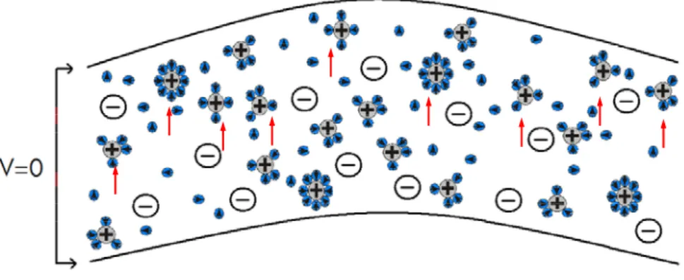
2.8: Initial neutral state of IPMC.
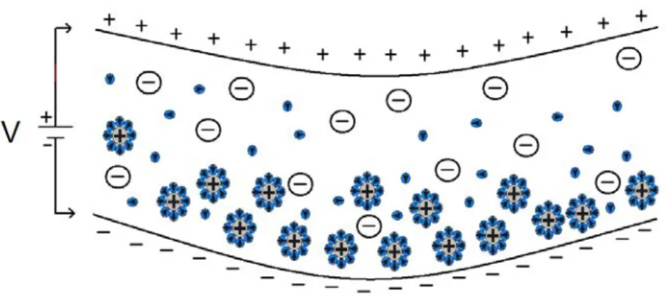
2.9: The interaction at the moment the voltage is applied to the electrode of IPMC. 2.10: Cations accumulation and forward bending after the voltage is applied.
2.11: Backward relaxation, water molecules are dragged back into the polymer matrix. 2.12: Redistribution of cations towards anode upon short circuiting the electrodes of IPMC. 2.13: Cations are slowly redistributed but a permanent deformation remains.
2.14: Three stages of Kanno-Tadokoro model (V: voltage, i: current, s: internal stress, ε: strain). 2.15: Equivalent circuit of the electrical stage presented by Kanno et al. (1996).
2.16: Signal transformation from current to internal stress for bending in Tadokoro Kanno model. 2.17: The linear coupling between the electrical and mechanical domains for Cantilevered IPMC in
Equivalent Circuit Model.
2.18: Actuator configuration for the Xiao and Bhattacharya’s Nonlinear Euler Bernoulli Beam Model augmented for Eigencurvature.
2.19: The response of the beam in terms of the deflected angle of the tip to a step voltage across the thickness.
CHAPTER 3
3.1: The sketch of an inner coated sample after the impregnation/reduction process. 3.2: Ion Exchange to Platinum salt.
3.3: Reduction mechanism of primary plating.
3.4: Relation between reducing agent and reduced Pt salt accumulation. 3.5: Descriptive sketch of cross section of the membrane after primary plating. 3.6: View of Nafion sheet at the moment of color change, first cycle of reduction. 3.7: Descriptive sketch of cross section of the membrane after primary plating. 3.8: View of successfully fabricated IPMC sheet after last cycle of secondary plating. 3.9: Cation exchange mechanism.
3.10: Cation exchange setup.
3.11: Fabrication setup for Electroless plating.
3.12: Compliant electrode surfaces, both with a magnification of 400. a. After 1 cycle of fabrication. b. After 8 cycles of fabrication (ANIM).
3.13: SEM photos of IPMC compliant electrode surfaces with a view angle of 60°, fabricated by the conventional technique (without plasma pre-treatment).
3.14: Plasma Etching and SEM Imaging of Nafion surface.
3.15: Details of the surfaces of Nafion after plasma pre-treatment, in squares of 3μm x 3μm, details taken from 4 extremities and centre of SEMFEG images, just after the plasma treatment. 3.16: Details of the surfaces of Nafion sample E17 after plasma pre-treatment, in squares of 3μm x
3μm, imaged with 20K magnification, details taken from 4 corner extremities (NW, SW, NE, SE) and centre of SEMFEG images, just after the plasma treatment, (LISE).
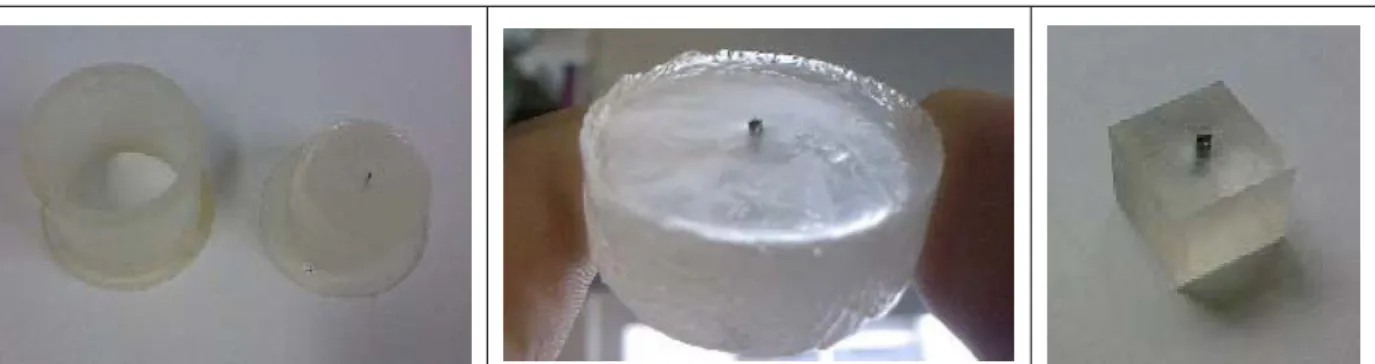
3.17: a. Geometrical coding for fabrication of IPMC in the same conditions. b. Fabricated IPMCs with this procedure.
3.18: Fabrication process of plasma-treated IPMC.
3.19: Form of electrodes of IPMC fabricated with plasma pre-treatment. From top to bottom, E15, E16, E17, E19 and E21; imaged with magnifications, from left to right, 5K, 10K, 20K and 50K. 3.20: Concept of dimension.
3.21: a. and b. Self similarity of natural structures, images from manual of Paul Bourke’s Fractal Calculator software, 2003.
3.22: Method for estimation of fractal dimension dB.
3.23: Scanning electron microscopic (SEM) photo of IPMC cross-section with a magnification of 200 times (ANIM).
3.24: Boundary region of Nafion membrane after first cycle of fabrication with a gradient of aggregated Pt particles to build the electrode surface, the scale shown in image is 20 μm (ANIM).
3.25: SEM Photos showing the increasing electrode thickness with repeated fabrication cycles. 3.26: Preparation of cross section sample by molding, cutting and polishing (LISE).
3.27: Cross section of IPMC fabricated with plasma pre-treatment, magnification 700 (LISE).
3.28: Section of Pt electrode having ~3 μm thickness seen at the interface of IPMC and resin used for sample preparation procedure, magnification 25K (LISE).
3.29: Sheet resistance measuring principle.
3.30: Sheet resistance measuring construction diagram and constructed measuring device.
3.31: Surface Resistivity of IPMC fabricated employing Plasma Treatment with parameters E15, first experiment.
3.32: Surface Resistivity of IPMC fabricated employing Plasma Treatment with parameters E15, second experiment.
3.33: Surface resistivity of IPMC fabricated employing plasma treatment with parameters E16, first experiment.
3.34: Surface resistivity of IPMC fabricated employing plasma treatment with parameters E16, second experiment.
3.35: Surface resistivity of IPMC fabricated employing plasma treatment with parameters E17, first experiment.
3.36: Surface resistivity of IPMC fabricated employing plasma treatment with parameters E17, second experiment.
3.37: Surface resistivity of IPMC fabricated employing plasma treatment with parameters E19, first experiment.
3.38: Surface resistivity of IPMC fabricated employing plasma treatment with parameters E19, second experiment.
3.39: Surface resistivity of IPMC fabricated employing plasma treatment with parameters E21, first experiment.
3.40: Surface resistivity of IPMC fabricated employing plasma treatment with parameters E21, second experiment.
3.42: Average surface resistivity of different IPMC samples as a function of fractal dimension estimated by binarized sampling, after one plating cycle.
3.43: Average surface resistivity of different IPMC samples as a function of fractal dimension estimated by grayscale sampling, after one plating cycle.
3.44: Novelty of our plasma etching technique for rapid fabrication of IPMC.
CHAPTER 4
4.1: Deflection of an IPMC actuator, square voltage, Vpp= 2V, f=0.1Hz (CNRS-UPR15-LISE). 4.2: Scheme of bending motion in first characterization (ANIM) setup with reference grating. 4.3: Frontal detail and sketch of the first designed characterization setup.
4.4: Sketch of the experimental setup with laser displacement sensor.
4.5: Sketch of the experimental setup constructed at LISE for IPMC characterization experiments. 4.6: a.Actuation assembly of IPMC and b. Interior design of orientable clamp carrying copper plates. 4.7: Actuation assembly for the IPMC characterization seen from above.
4.8: Displacement of IPMC (length 40 mm with laser spot at 25 mm from the fixation) in water. 4.9: Overall deflection duration versus voltage (using setup ANIM-1).
4.10: Bending of IPMC for different sides (using setup ANIM-1).
4.11: Successive photos of actuation of a Nafion-based IPMC under DC voltage.
4.12: IPMC with cation H+ actuated under 2V and short circuited, in water (using setup ANIM-2). 4.13: Time variation of tip deflection observed for Environmental Robotics (Na+ doped) IPMC with
Au electrodes, actuations in water 2V-4V.
4.14: Early time variation of tip deflection observed for Environmental Robotics (Na+ doped) IPMC with Au electrodes in water, first second of actuations.
4.15: Time variation of tip deflection observed for Environmental Robotics (Na+ doped) IPMC with Au electrodes, actuations in air 2V-4V.
4.16: Early time variation of tip deflection observed for Environmental Robotics IPMC (Na+ doped) with Au electrodes in air, first second of actuations in air 2V-4V.
4.17: Time variation of tip deflection observed for Environmental Robotics (Na+ doped) IPMC with Pt electrodes, actuations in water, 2V-3V.
4.18: Early time variation of tip deflection observed for Environmental Robotics (Na+ doped) IPMC with Pt electrodes in water, first second of actuations.
4.19: Time variation of tip deflection observed for IPMC in Water with Cation H+, actuated under 2V-3V / after short circuit.
4.20: Time variation of tip deflection observed for IPMC, cation Na+, in water, actuated under 2V - 5V and shorted.
4.21: Time variation of tip deflection observed for (Na+ doped) IPMC in water first second of actuation.
4.22: Time variation of tip deflection observed for IPMC doped by Li+ cation, actuated in air under 2V - 4V and shorted.
4.23: Time variation of tip deflection observed for IPMC TBAOH+/Na+ form; actuation performances (in air) after 2 different durations of cation processing.
4.24: a. Time variation of tip deflection shown in time scale of 10 seconds for IPMC Na+ doped actuated under 1Hz ±2Vpp square voltage. b. Detail of vibrations on a smaller time scale. 4.25: Time variation of tip deflection observed for IPMC Na+ cation actuated under 10 Hz. ± 2Vpp
square voltage, in a time span of 1 second.
4.26 a. and b.: a. Tip deflections of IPMC (E16) actuated by square voltage 1.0 Vpp with 0.5 Hz, different observation lengths (10, 15, 20 mm) b. Detail over one period.
4.27: Free deflections of IPMC (E16) at measurement points at a. 10 mm, b. 15 mm and c. 20 mm; actuated by square voltages of 1V, 1.5V and 2V, with frequency 0.5 Hz.
4.28: IPMC under +/-1.0 Vpp square f=0.5 Hz, detailed time-dependent view of actuation.
4.29: Form of IPMC E16 (cross section view) at t=0.7 s after the beginning of actuation, Triangular, from +/-0.5 to +/-2.5 Vpp.
4.30: The evolution of current as a function of applied voltage after 1, 2 and 3 seconds of actuation. 4.31: Response of IPMC (E16) of length 10mm, under 2.5V, shorted at t=120 s. a. Deflection and
current. b. Detail around the short circuiting.
4.32: Response of IPMC (E16) for Voltages 0.5V to 2.5V, around the moment of short circuiting the electrodes at t=120s. a. Detail of current response. b. Logarithmic - linear plot of the current response starting from the short circuiting point (t=120s).
4.33: Detail of deflection response at the moment of short circuiting.
4.34: Surface plot of actuation characteristics of IPMC with respect to the applied voltages and lengths of the IPMC, (E16-triangular input).
4.35: Current vs. voltage during the cyclic voltammetry of the IPMC E16, Voltages from 0.5 to 2.5 Vpp.
4.36: Schematic representation of curvature response characterization and parameters used in characterization of curvature response.
4.37: Curvature response of an IPMC of length 15.35 mm under 2V step voltage.
4.38: a. Experimental setup for loaded deflection experiments. b. Detailed view of actuation measurement section in experimental setup for Young’s Modulus.
4.39: Time dependent deflection of IPMC at 15.85 mm. from fixing point, against different loads (counter forces), excitation voltage 2V.
4.40: Differences between time dependent deflections for different loads (counter forces) for IPMC at 15.85 mm. from fixing point, actuation voltage is 2V.
4.41: Cantilevered beam deflects uMAX when subjected to a force F.
4.42: The dimension parameters of IPMC.
4.43 a.b.c.d.: Effect of load annulations on deflection of IPMC a. after 3, b. after 10 and c. after 30 seconds. d.: Calculated Young's Modulus of IPMCs vs. positions of the test weights.
4.44: Dynamic Behavior of Young’s Modulus. Change of magnitude of Young’s Modulus with time after the start of actuation.
4.45: Back relaxation of IPMC observed in the dynamic behavior of Young’s Modulus.
4.46: Fitting curve for tip deflection of IPMC (E16), 10 mm length, actuated by 0.5Hz 1.0 Vpp square voltage.
4.48: a. Local minima and maxima of vibration extracted from the difference curve. b. Frequency of this vibration during actuation.
4.49: Linear response of current to a sinusoidal low amplitude perturbation of potential of around a stationary value VS.
4.50: a. Equivalent circuit of an electrochemical cell and b.: Nyquist plot of the electrochemical impedance.
4.51: Bode frame plots of a. Modulus and b: Phase of electrochemical impedance.
4.52: a. Proposed equivalent circuit and b. Nyquist frame plot of the electrochemical impedance of IPMC.
4.53: Experimental impedance diagram (transfer function ) corresponding to sample E15 (bias= 0V).
/
V i
4.54: Electrical equivalent circuit simulating the impedance diagrams of a blocked Nafion film in EIS (Electrochemical impedance spectroscopy) experiments.
4.55: Electrical equivalent circuit simulating the impedance diagrams of a blocked Nafion film in EIS (Electrochemical impedance spectroscopy) experiments when faradaic reactions take place at the bounding electrodes.
4.56: Schema of the experimental setup for electrochemical impedance and transfer functions measurements.
4.57: Actuation of the E16 IPMC under +/-0.5 V sinusoidal input, f=0.5 Hz L=5 mm. Current, voltage and deflection vs. time.
4.58: transfer function for E15, E16, E17, E19 and E21 samples, different biases and 0.3 V as signal amplitude. a1 to k1 curves correspond to Nyquist coordinates (Real part, -Imaginary part), a2 to k2 curves correspond to Bode coordinates (log(modulus), Phase shift (degree) vs. log (frequency)). a3, c3, i3 are transfer functions.
V / i
u / i
4.59: Transformer schema used in the work by Newbury and Leo to describe the electromechanical coupling assigned to an IPMC.
4.60a: Experimental () and fitted () diagrams for the transfer function. Nyquist diagram (real
part/-imaginary part) is displayed on the left hand side. Bode diagrams (modulus vs. log frequency, phase shift vs. log frequency) are displayed on the right hand side. Sample number E15, potential bias 0.5V.
V / i
4.60-b: Same as in Fig 4.60-a. Sample number E15, potential bias 0 V. 4.60-c: Same as in Fig 4.60-a. Sample number E16 Li+, potential bias 0.5 V. 4.60-d: Same as in Fig 4.60-a. Sample number E16 Li+, potential bias 1.5 V. 4.60-e: Same as in Fig 4.60-a. Sample number E16 Li+, potential bias 1 V. 4.60-f: Same as in Fig 4.60-a. Sample number E17, potential bias 0.5 V. 4.60-g: Same as in Fig 4.60-a. Sample number E17, potential bias 0 V. 4.60-h: Same as in Fig 4.60-a. Sample number E19, potential bias 0 V. 4.60-i: Same as in Fig 4.60-a. Sample number E21, potential bias 0.5 V. 4.60-j: Same as in Fig 4.60-a. Sample number E21, potential bias 0 V. 4.60-k: Same as in Fig 4.60-a. Sample number E21, potential bias 1 V.
CHAPTER 5
5.1: Linear model of muscle static force production.
5.2: Mc Kibben muscle before (a) and after (b) actuation (Shadow Robot Company). 5.3: Braided sheath and rubber tube.
5.4: Decrease in static force with contraction ratio.
5.5: Schematic representation of the experimental apparatus with antagonistic pair of actuators. 5.6: Antagonist torques acting on the same joint.
5.7: Experimental apparatus used to test the models.
5.8: Experiment vs. simulation of a Mc Kibben Muscle leading to the empirical factor k, k~0.7. 5.9: Finger bones and joints.
5.10: Each joint is actuated with a different antagonist pair of muscles. 5.11: In the Robotic formalism, each joint is assigned a coordinate frame.
5.12 a. and b.: Three d.o.f. robotic arm configurations a. with robotic parameter α nonzero, b. with robotic parameter d nonzero.
5.13: The three degrees of freedom sequence in the workspace frame with three consecutive reference frames shown with their D-H parameters.
5.14: Alignment of initial configuration of the finger with a series of Denavit-Hartenberg transformations.
5.15: Simulator of finger actuated by with 3 pairs of pneumatical artificial muscles, tendons are hidden in the arm.
5.16: The locations of antagonist Mc Kibben Muscles seen in the upper view. The antagonist muscle pairs are indicated with the same color.
5.17: Finger segment angular velocities and accelerations during actuation.
5.18: The experiments previously made on the setup show the actuation of one joint actuated by different P.
5.19: The angular flexion trajectories of the three joints of the index finger in the experiments of Cole and Abbs (1986).
5.20: IPMC cantilever beam located in coordinate axis.
5.21: Diagram for the loop design in Simulink model for the Static Deflection model of IPMC. 5.22: Resulting graph of the model for Euler-Bernoulli Equation of cantilevered beams.
5.23: Actuator configuration for the Xiao and Bhattacharya’s Nonlinear Euler-Bernoulli Beam Model augmented for Eigencurvature.
5.24: Modified configuration of Xiao and Bhattacharya’s IPMC model for horizontal force.
5.25: Comparison of Experiment and Nonlinear Euler Bernoulli beam model augmented for Eigencurvature.
5.26: Simulation results a. for IPMC curvature response and b. for IPMC tip deflection response. 5.27: Simulation results, single IPMC actuator at initial (cyan) and final (green) states. Code of the
simulator is presented in Appendix A5.3.4.
5.28: Model results for IPMC tip deflection response vs. time with different counterloads and without load.
5.29: Experiment results for IPMC deflection response vs. time with different counterloads and without load.
5.30: Longitudinal Contractile Actuator model.
5.31: Simulator of longitudinal-contractile IPMC actuator.
5.32: Simulation result a. for IPMC curvature response and b. for the longitudinal contractile tip deflection response, for the same conditions cited in Fig. 5.26.
5.33: Side views (above), oblique view and upper view (below) of the longitudinal contractile actuator. 5.34: a. and b.: Longitudinal contractile IPMC actuator prototype with free tips and voltage applied
at the midpoints. a. Neutral state, b. Actuated state.
APPENDICES:
A.1.1: Construction of a Dielectric Elastomer Actuator.
A.1.2: Functioning of roll-spring Dielectric Elastomer Actuator.
A.1.3: Dielectric Elastomer Actuation profiles actuated under 3KV to 4.5 KV.
A.1.4: First second of actuation profiles for Dielectric Elastomer Actuator actuated under 3KV to 4.5KV.
A.1.5: Maximum Displacement Variation of Dielectric Elastomer Actuator for actuation voltage between 3.5 an 4 kV.
A3.1: The surface resistance measurement method for the test of surface electrode quality. A4.1: Labview code for the Experimental Setup for Characterization of IPMC.
A4.2: Interface of the Labview acquisition program. A4.3: Detail of the IPMC positioning assembly.
A4.4: Positioning assembly [x,y,z] for displacement sensor.
A4.5: Device for changing the distance of the observation point on IPMC.
A5.1: Interface of simulator with pressure differences for Mc Kibben actuated finger. A5.2: Angle response calculated by analytical solution.
A5.3: Angle response calculated by numerical solution.
A5.4: Simulink model for Euler Bernoulli equation of cantilevered beam. A5.5: Strain Energy of Bending.
List of Tables
1.1: Parameters of dielectric elastomer actuation.
1.2: Comparison of IPMC, SMA and EAC performances.
2.1: Schematic representations of IPMC elements responsible for actuation.
2.2: Explanations proposed for forward bending of IPMC by different physical models. 2.3: Explanation s proposed for backward relaxation of IPMC by different physical models.
2.4: Explanation s proposed for the reverse actuation of IPMC due to short circuiting after actuation by different physical models.
2.5: Explanation s proposed for the permanent deformation of IPMC after shorting and reverse actuation by different physical models.
2.6: Comparison of models regarding their input and output parameters.
3.1: Proposed methods for surface roughening of the membrane material. 3.2: Proposed method for acid treatment of the membrane material. 3.3: Proposed methods for preparing the ion exchange solution. 3.4: Proposed methods for cation exchange.
3.4: Proposed number of cycles of fabrication.
3.5: Plasma etching parameters used for the etching-imaging experiments.
3.6: Surface Dimensions of Etching Experiments by box counting method, averages and Normalized Standard deviations.
3.7: Surface Dimensions of Etching Experiments by differential box counting method, averages and Normalized Standard deviations.
4.1: Young’s Modulus Experiment Data.
4.2: Bias values that were used for electrochemical impedance measurements of IPMC samples. 4.3: Fitted values of the parameters of equation (4.28).
5.1: Robotic Parameters for Forward Kinematics of Three Segments Finger. 5.2: Simulation parameters for IPMC actuator.
Introduction
Recent developments in material science, material processing and device design enable today the scientific and industrial community to concentrate their efforts in the development of different kinds of “pseudo-muscular” actuators (or “artificial muscles”), by using the Electro Active Polymers (EAP), which are able to show electrically-induced deformations.
The need for biological-like artificial muscle is emerging from two directions: First, for the use of robots which enables to imitate the biological functions but also to improve our knowledge on the structure and behaviour of the Central Nervous System. Second, for the humanoid applications that requires more and more precise, flexible, adaptable, i.e. biological plausible actuators.
The range of speed and precision of muscle actuation in a high-performance artificial muscle would revolutionize robotics. The essential characteristics of
non-linearity, time-dependance, repetability and high level of control make the imitation
of biological muscle a very hard engineering challenge. Moreover, the complex molecular structure of muscle, for the moment, precludes the direct imitation of muscle. Therefore, the development of artificial muscle is rather oriented on the search for materials and mechanisms that could conceivably display muscle-like characteristics at a macro-level.
Electroactive polymers are a recently discovered class of active materials that exhibit electromechanical coupling. Ionic Polymers can be used as “soft” transducers and have a combination of characteristics that makes them well suited to
biological-like applications. Before considering ionic polymers as a viable actuator technology, their capabilities and limitations must be well understood and documented. Also, to facilitate the actuator design process, simple but accurate models must be developed.
The primary goals of this work are to fabricate, characterize and model the behavior of ionic polymer actuators at a macroscopic level. A secondary objective is to demonstrate an application system that employs longitudinal contractile muscle-like actuators. A third objective is to design longitudinal contractile ionic polymer
transducers for actuation. A fourth objective is the improvement of fabrication and
characterization procedures of these actuators.
This manuscript is prepared to present the work for fabricating, characterizing and modeling electroactive polymer actuators, eventually in order to serve realization
of a longitudinal biomimetic artificial muscle. The objective of each part of this work,
and the achieved points are presented. The first chapter is intended as a review of
artificial muscle actuators. Next chapter presents our review of modeling Ionic Polymer Metal Composite (IPMC) actuators. Afterwards, the fabrication, characterization work and related transducer modeling work are presented. The finger model and its actuation simulation with pneumatic artificial muscles are documented. The proposed longitudinal actuator and its developed model are demonstrated.
In Chapter 1, our review starts by examining biological muscle as an actuator, and then various types of biomimetic actuators are presented, with a complete section on Ionic Polymer Metal Composite (IPMC).
In Chapter 2, we continue with a general review on modeling of IPMC, presenting empirical, physical and gray box models. The actuation mechanism of IPMC is detailed with a section on comparative explanation of IPMC actuation mechanisms with different physical models.
In Chapter 3, Fabrication and Morphological Characterization of IPMC, a new fabrication method that is elaborated for IPMC using a plasma treatment, which enables a high efficacy and quality of fabrication in a limited time, is presented. Next, the morphological characterization and sheet resistance characterization work for the IPMCs we fabricated by this method is presented.
In Chapter 4, Experimental characterization of mechanical and electrical properties of IPMC, the results of our characterization experiments are presented, with a complete section on our studies of Young’s modulus of IPMC that contains two new methods of characterization. An Impedance Analysis of IPMCs realized with an experimental setup enabling simultaneous observation for different parameters is presented.
In Chapter 5, modeling work is presented. A model for a biomimetic artificial hand actuated by contractile longitudinal pneumatic (Mc Kibben) actuators is presented to illustrate biological plausibility of these actuators. Next, starting by modeling one IPMC strip, a new contractile longitudinal actuator that was designed using multiple IPMCs is proposed, with its model. Fabricated prototypes of this actuator are presented.
Chapter 1
General Review: From the Biological
Muscle to the Biomimetic Actuators
1. BIOLOGICAL MUSCLE AS AN ACTUATOR
Muscles are highly optimized systems as a result of evolutionary processes within the course of millions of years. They are fundamentally driven by the same mechanisms in all animals which are bigger than bacteria and the differences between
species are insignificant. This is a clue for the degree of its optimization level. Muscles
are capable of lifting large loads with short time response in the millisecond range. Muscle cells have a cylindrical shape with diameters ranging between 10 and 100 m and their length may go up to several centimeters. The average power density ranges from 9 to 284 W/kg (Altringham et al 1993, in [1]) with an energy density of 20-70 kJ/kg [1]. The power decreases with increasing speed of actuation. Although muscles produce linear contractile forces, all motions at joints are rotational and this is enabled by antagonistic pair configuration of muscles. Thus, the mechanical properties of the joint play an important role on the performance of muscles.
Since the primary purpose of skeletal muscle is to generate force and movement and since this function is substituted by motors, machines and materials, it is
important to first understand the mechanical basis of muscle functioning (Figure 1.1).
Fig. 1.1: Structural hierarchy of skeletal muscle from muscle to myofibrils [2]. The largest functional unit of contractile filaments is the myofibril (literally, "muscle thread"). Myofibril is a string of sarcomeres arranged in series. Myofibrillar diameter is about 1 m, thus thousands of myofibrils can be packed into a single muscle fiber. Myofibrils are arranged in parallel (side by side) to make up the muscle fiber. Groups of muscle fibers are surrounded by a connective tissue sheath known as perimysium (literally, "around muscle") and arranged in bundles called fascicles. These fascicles are also bundled together, surrounded by more connective tissue (epimysium, literally, "on top of muscle") to form the whole muscle, which we can inspect visually. Myofibrils are subdivided into their component units known as sarcomeres, the functional unit of muscle contraction.
The total number of sarcomeres within a fiber depends on the muscle fiber length and diameter. Because of the series arrangement of sarcomeres within a myofibril, the total length of myofibrillar shortening is equal to the sum of the individual shortening lengths of the individual sarcomeres. This is why a whole muscle may shorten by several centimeters even though each sarcomere can only shorten by about 1 m. It should also be stated that the number of sarcomeres in a mature muscle can change given the appropriate stimulus. This gives skeletal muscle a tremendous ability to adapt.
There are two basic types of muscle, smooth and striated. Smooth muscle is used for slow rhythmic movements, such as movement of food through the intestine, whilst
striated muscle can be further divided into skeletal (voluntary) and cardiac muscle.
Muscles always actuate in a contractile manner, so voluntary muscles always exist in antagonistic pairs so as to provide a full range of movement to the area of the body they actuate. They can therefore be divided into flexor or extensor muscles depending on their role within the pair (for example triceps are extensors, biceps are flexors).
The mechanism of operation of muscles is reversible hydrogen bonding reaction between two proteins: actin and myosin. Actin and myosin form a loose complex called actomyosin. ATP (Adenosine Triphosphate) is a multifunctional molecule that plays an important role in cell biology, which transports chemical energy within cells for metabolism. Figure 1.2 represents the actuation that results in this phenomenon. The longitudinal contractions obtained in billions of actomyosin complexes are superposed in the muscle structure to yield the contraction that actuates our joints.
Fig. 1.2: The actuation of the actomyosin complex from loose complex to the concentrated complex [3].
When ATP is added to actomyosin, the protein fibers contract. The hydrolysis of ATP transforms it into ADP (Adenosine diphosphate) and releases energy which is used by muscles for contraction. The coupled reaction is:
ATP + H2O --> ADP + P + energy
Relaxed muscle + energy --> contracted muscle
The release of Ca2+ ions is responsible for starting and stopping the three
dimensional structure changes which yields the muscle striction.
2. VARIOUS TYPES OF BIOMIMETIC ACTUATORS
Unlike existing linear actuators that could be considered roughly analogous to muscle (such as hydraulic actuators for example), the muscle is a highly nonlinear and time variant component of the animal system. These essential characteristics of non-linearity, time-dependence, repetability and high level of control make the imitation of living muscle a very hard engineering challenge. The benefits of achieving a high-performance artificial muscle are obvious; the range of speed and precision of muscle actuation would revolutionize robotics.
The complex molecular structure of muscle precludes the direct imitation of muscle. The development of artificial muscle is therefore centered on the search for materials and mechanisms that could conceivably display muscle-like characteristics at a macro-level. There exist at present several candidate materials and mechanisms that are being considered as suitable for artificial muscles. These include:
Actuators driven by biological materials Mc Kibben pneumatic muscles
Shape Memory Alloys
Other actuator types: Magneto-active and photo-active gels Electro Active Polymers (EAP)
2.1 Actuators driven by biological materials
Most of the work for creating artificial muscles is concerned with the search for materials such as EAPs that exhibit muscle-like behavior at a macro-scale. Nevertheless, there are researches on the imitation of the sarcomere structure of the muscle in order to achieve the desired performance. Large-scale fabrication of the complex structure of muscle is not practical at present, but the microscopic scale of individual actin filaments and myosin motor proteins can enable using such elements
to provide nanoscale actuation in biomimetic applications. Since these biomotors are powered by ATP instead of electricity, they can theoretically compete with human
cells in vivo. ATP can be artificially synthesized since 19481.
The action of a myosin head across an actin filament has been extensively studied and their possibility as microscopic actuating mechanisms for use in micro and nano-devices has been established. [Kitamura et al., 1999]) However, the difficulty in using actual muscular components (ATP-driven motor proteins such as myosin, kinesin and dynein) is their requirement for a specific chemical environment (principally containing ATP) in order to function. Another drawback is that biomotors are sensitive to temperature, pH, and need a liquid environment.
2.2 Mc Kibben Pneumatic Muscles
McKibben artificial muscle was originally developed in the 1950’s as an orthotic
appliance that support musculoskeletal deformities commonly seen in polio patients
.
(Nickel et al., 1963 [4], Klute et al., 1999 [5]). It is also called “Braided pneumatic actuators” (BPAs) or “rubbertuator” in some sources. It is powered by compressed gas, which is fed into an actuator that is composed of an inflatable inner rubber sheathed with a double helical weave. Figure 1.3a represents its working principle: When the gas enters, the bladder increases in volume, expanding radially and contracting along its length. It is used in pairs for a biomimetic actuation (see Figure 1.3b).
a. b.
Fig. 1.3: a. Mc Kibben muscle in relaxed and actuated states.
b. Two antagonistically connnected McKibben artificial muscles.
The force produced is related to pressure in the tube, radius of the tube and the angle between the two helices of the double helical (braided) shell tissue. An application of this muscle is presented in Chapter 5.
2.3 Shape Memory Alloys (SMAs)
Shape Memory Alloys are a well-developed technology, and there already exist several commercially available products using SMAs. SMAs work in a cycle between heated and cooled conditions, adopting a specific geometry within each phase. Usually the heated condition is achieved by the Joule effect, but the material can also be heated by radiation or convection. The most common SMA is Nitinol (an alloy of Nickel and Titanium) and wires are commercially available in several diameters normally ranging from 50m to 250m. Nitinol has an energy conversion efficiency of around 5%, and a work output of around 1 kW/kg, to be compared to the work output range of 9 to 284 W/kg for the biological muscle.
SMA wires with a length contraction of 4% can achieve deformation 100 times larger when used in spring configurations. On the other hand, the force in wire configuration is 15 times larger than in spring configuration. When current is established between the two ends, the SMA spring is heated by Joule effect and
contracts (transition of the alloy to an austenitic phase), at 70°C for Nitinol. It can
be, for example, used in an artificial earthworm application [6], which is composed of numerous contracting shells. The SMA spring contracts and bends the silicone shell seen in Figure 1.4 towards inside. Once the current is cut off, the SMA spring cools and turns back to the plastic phase (martensitic phase at low rigidity), and the silicone shell can recover its original shape decontracting towards outside, thus pulling the SMA spring to its original length.
Fig. 1.4: An application of SMA wires in spring form for earthworm module application.
SMAs have been proposed as actuators for solar panels, adaptative structures such as wings for optimizing shape at given velocity and pressure. They can be easily set to remember different initial shapes. They have a low reaction speed and require
thermoelectric sources and a heat sink. In a recent study, SMAs with three phases thus having two remembered shapes are fabricated.
2.4 Magneto-active and photo-active gels
Magneto-active and photo-active gels are non-electrically -mechanically or
chemically- activated polymers that exhibit a volume or shape change in response to
a perturbation of the balance between repulsive and attractive intermolecular forces. The competition between these forces can be controlled by small changes in parameters such as composition of a solvent or gel, temperature, pH etc. These types of polymers include magnetically (Fig 1.5), chemically (Fig 1.6) and light-activated (Fig 1.7) shape memory polymers, and inflatable structures.
a) b)
Fig. 1.5: Shape distortion of a ferrogel, due to a non-uniform magnetic field produced by a permanent magnet [7,8] when: a) the gel is located 15 cm from the magnet b) The magnet is placed under the ferrogel.
Fig. 1.7: Image of Poly(Nisopropylacrylamide) (PNIPAM) gel rod in D2O before (a) and after (b) illumination by a 0.75 W power laser source at 1064 nm wavelength [10].
2.5 Electro-active materials based actuators
2.5.1 Electroactive Ceramics
Piezoelectricity is an electromechanical phenomenon where piezo materials
produce a voltage when subjected to a mechanical stress and the vice versa. Piezoelectric effects were discovered in 1881 by Pierre Curie together with his brother Jacques Curie. First ceramic capacitor was fabricated in 1931. Electroactive Ceramics are used in low strain actuator applications, as sensors, ultrasonic transducers, sonar technology and for ultrasonic cleaning and welding. In biomimetic actuation
applications, its disadvantage is the low strain range up to 1%. Recently there have
been biomimetic actuator application propositions with small strain [11]. The actuation principle is explained in Figure 1.8.1. They can be fabricated in a wide range of dimensions to fulfill the requirements of different tasks (Figure 1.8.2).
Fig. 1.8.1: Actuation principle of electroactive ceramics. (a) Disk after polarization. (b) Voltage applied at the same polarity as the poling voltage: disk lengthens
(c) Voltage applied at the opposite polarity as the poling voltage: disk contracts
Fig. 1.8.2: Electroactive ceramic actuators are available with various diameters and lengths [12].
2.5.2 Carbon nanotubes (CNTs)
Carbon nanotubes (CNTs) are the most recent addition to the class of electroactive materials. They are hollow cylinders consisting only of carbon; they can be described as a graphite film rolled to form a tube. Carbon nanotubes have lengths
about 1000 times their width (typical diameters are about 10 Angstrom, with typical
lengths about 1 micrometer) and typically they are combined in bundles of 100 Angstrom diameter. Carbon nanotubes can be divided in two classes: single-wall and multiwall. A single-wall CNT consists in a single film rolled to make a tube, while a multi-wall CNT is made of several films rolled one on the others. A double walled carbon nanotube is shown in Figure 1.9. Mechanical performances of multiwall tubes are predicted to be lower, with respect to those predicted for the single-wall ones,
considering the lower forces between the layers.
Fig. 1.9: A double walled Carbon Nanotube.
These sheets are either conductive or semi-conductive. CNT papers and fibers are filtered or spun from large numbers of nanotubes suspended in solution and are actuated by placing them in an electrolyte and activating them using an apparatus very similar to that used for conducing polymers [13]. The application of an electrical potential causes the formation of an electrical double layer at the nanotube/electrolyte interface, in which the electronic charge stored in the carbon atoms is balanced by the ionic charge in the liquid phase. The accumulated charge stored in the nanotube causes a change in the C-C bond length during electron injection, producing strains of up to 1%. Although the strains are small, individual carbon nanotubes are believed to exhibit important tensile strengths.
2.5.3 Electro-Active Polymers (EAPs)
Electroactive polymers exhibit an electro-mechanical response (i.e. undergo deformation) when a voltage is applied across them, enabling their use as actuation devices []. Since the beginning of the 1990s the development of a series of new electroactive materials that can induce large strains has led to a review of their possible application as artificial muscles.
Electroactive polymers are not restricted by the displacement limitations of rigid electroactive ceramics, making them more suitable for applications requiring larger deformations [Shahinpoor et al., 1998], [Bar-Cohen et al., 1999]. Furthermore,
electroactive polymers have demonstrated high strain (larger than many of artificial
muscles), high efficiency and energy density, fast response, and good controllability. Electroactive polymers are superior to shape memory alloys in spectral response, density and resilience.
EAP materials can be classified in two categories:
i) Electronic EAP (activated by an external electric field and by Coulomb forces):
• Electrostrictive polymers
• Dielectric elastomers
ii) Ionic EAP (activated by an electrically-induced transport of ions or molecules):
• Polyelectrolyte gels
• Electronically Conducting Polymers, (ECP) • Ionic polymer metal composites, (IPMC)
2.5.3.1 Electronic EAPs
In electronic EAPs, the coupling is dominated by electrostatic forces. Relative to ionic EAPs, electronic EAPs respond rapidly (milliseconds) and require high fields (on the order of 1MV/m) for actuation.
2.5.3.1.1 Electro-strictive polymers
Electrostriction is an electro-mechanical coupling phenomenon shown by any dielectric material. It consists of a quadratic dependence of the strain and stress with the material polarization due to an applied electric field. An electroactive polymer structure using this principle is shown in Figure 1.10. For materials showing a linear
relation between polarization and applied electric field (E), the electrostrictive strain (or stress) depends on Q (the polarization-related electrostriction coefficient) and the square of E.
Strain=QE2
Fig. 1.10: Structure and morphology of Electrostrictive Graft Elastomers.
These materials produce moderate amounts of force and displacement, they can be used for diaphragm actuators (such as actuators for pumps), or bending beam actuators as well as directly linear actuators. Their high efficiency and very fast speed of response also make them well suited for producing sound or ultrasound. They are less effective than dielectric elastomers.
2.5.3.1.2 Dielectric Elastomer Actuators
Dielectric Elastomer Actuator (DE Actuator or DEA) is the name for a class of actuators with very promising properties. They are basically compliant capacitors, made of a thin elastomer (soft rubber) film sandwiched between two compliant electrodes. Dielectric elastomers actuators have a low elastic modulus and when subjected to a high electric field they exhibit large deformations, mainly due to the electrostatic interactions (Coulomb effect) among the free charges on the electrodes. This working principle is shown in Figure 1.11. When a voltage between the compliant electrodes is applied, the arising electrostatic pressure (Maxwell pressure) squeezes the elastomer film in thickness and the film gets thinner, resulting in an
expansion in the plane of the film. Maxwell pressure is described by:
2 2 2 0 0
V
p
E
d
(1.1)p Maxwell’s Stress, F/A
relative dielectricity of elastomer V Applied Voltage (3 – 5 kV) 0
dielectricity of space d width of elastomer E Applied Electric fieldTable 1.1: Parameters of dielectric elastomer actuation.
The performance of DE actuators depends on the material from which they are
fabricated. VHBTM, which is a common material used in dielectric elastomer actuator
fabrication, is a firm acrylic foam tape that is used for bonding a variety of substrates.
DE actuators can generate forces and displacements comparable with muscles of a similar size and respond rapidly.
Fig. 1.11: Dielectric elastomer actuator working by principle of Maxwell pressure, configurations before and after actuation.
A linear DEA can be fabricated by rolling the DEA sheet to a spring.2 An
experimental setup for the electromechanical characterization of such longitudinal dielectric elastomer actuators has been realized (Figure 1.12). The power is supplied by a high voltage (kV) power supply to the dielectric elastomer actuator. A metallic
disc with mass 610 g. is hooked to the tip of the DEA. The laser displacement sensor
is placed under this assembly to measure the resulting elongation during actuation. When the voltage is applied, the DEA elongates and the weight descends
continuously and almost instantaneously and when the voltage returns to 0, DEA
contracts and the weight ascends with the attracting force of the spring.
2
For fabrication of such Dielectric Elastomer Actuators and the results of their electromechanical characterization experiments see Appendix A.1.
![Fig. 1.2: The actuation of the actomyosin complex from loose complex to the concentrated complex [3]](https://thumb-eu.123doks.com/thumbv2/123doknet/14743828.755577/33.892.203.715.617.894/fig-actuation-actomyosin-complex-loose-complex-concentrated-complex.webp)

![Fig. 2.3: a. Momentum conservation in the membrane. b. Electrostatic force caused by fixed negative charge of anionic groups in Nafion [5]](https://thumb-eu.123doks.com/thumbv2/123doknet/14743828.755577/63.892.205.709.105.343/momentum-conservation-membrane-electrostatic-caused-negative-anionic-nafion.webp)
![Fig. 2.17: The linear coupling between the electrical and mechanical domains for Cantilevered IPMC in Equivalent Circuit Model [22]](https://thumb-eu.123doks.com/thumbv2/123doknet/14743828.755577/76.892.253.668.388.653/linear-coupling-electrical-mechanical-domains-cantilevered-equivalent-circuit.webp)