HAL Id: tel-02500736
https://tel.archives-ouvertes.fr/tel-02500736
Submitted on 6 Mar 2020HAL is a multi-disciplinary open access archive for the deposit and dissemination of sci-entific research documents, whether they are pub-lished or not. The documents may come from teaching and research institutions in France or abroad, or from public or private research centers.
L’archive ouverte pluridisciplinaire HAL, est destinée au dépôt et à la diffusion de documents scientifiques de niveau recherche, publiés ou non, émanant des établissements d’enseignement et de recherche français ou étrangers, des laboratoires publics ou privés.
cycle thermal micromachine with stirling cycle
Alpha Dassimou Diallo
To cite this version:
Alpha Dassimou Diallo. Contribution to the design and fabrication of a Stirling cycle thermal mi-cromachine with stirling cycle. Electric power. Université Bourgogne Franche-Comté, 2019. English. �NNT : 2019UBFCD035�. �tel-02500736�
THESE DE DOCTORAT DE L’ETABLISSEMENT UNIVERSITE BOURGOGNE FRANCHE-COMTE
PREPAREE A L’INSTITUT DE RECHERCHE FEMTO-ST
Ecole doctorale n°37
Ecole Doctorale SPIM
Doctorat de Sciences pour l’ingénieur
Par
M. Alpha Dassimou DIALLO
CONTRIBUTION A LA CONCEPTION ET A LA REALISATION D'UNE MICROMACHINE THERMIQUE A CYCLE
DE STIRLING
Thèse présentée et soutenue à Besançon, le 11 Octobre 2019.
Composition du Jury:
M. Skandar BASROUR Mme Lavinia GROSU M. Tarik BOUROUINA Fabien FORMOSA Michel DE LABACHELERIE François LANZETTA Magali BARTHES Sylvie BEGOT
Professeur, Univ. Grenoble MCF HDR, Univ. Paris Nanterre Professeur, Univ. Paris-Est
Professeur, Univ. Savoie Mont Blanc DR CNRS, FEMTO-ST
Professeur, Univ. FC, FEMTO-ST MCF, Univ. FC, FEMTO-ST MCF HDR, Univ. FC, FEMTO-ST Président Rapporteur Rapporteur Examinateur Directeur de thèse Codirecteur de thèse Co-encadrante de thèse Co-encadrante de thèse
DOCTORAL THESIS OF THE UNIVERSITY OF BOURGOGNE FRANCHE-COMTE
PREPARED AT THE FEMTO-ST RESEARCH INSTITUTE
Title
CONTRIBUTION TO THE DESIGN AND CONSTRUCTION OF A THERMAL
MICROMACHINE WITH STIRLING CYCLE
Author
M. Alpha Dassimou DIALLO
Composition of the Jury:
M. Skandar BASROUR Mme Lavinia GROSU M. Tarik BOUROUINA Fabien FORMOSA Michel DE LABACHELERIE François LANZETTA Magali BARTHES Sylvie BEGOT
Professeur, Univ. Grenoble MCF HDR, Univ. Paris Nanterre Professeur Univ. Paris-Est
Professeur, Univ. Savoie Mont Blanc DR CNRS, FEMTO-ST
Professeur, Univ. FC, FEMTO-ST MCF, Univ. FC, FEMTO-ST MCF HDR, Univ. FC, FEMTO-ST Président Rapporteur Rapporteur Examinateur Directeur de thèse Codirecteur de thèse Co-encadrante de thèse Co-encadrante de thèse
Page 3 on 229
A Dieu, qui a enjoint à l’Homme de la bonté envers ses père et mère : sa mère l’a
péniblement porté et en a péniblement accouché ; et sa gestation et sevrage durent
trente mois.
À mes parents, Amadou Kindy et Fatimatou Diallo, comme ils m’ont élevé tout
petit alors que je n’étais rien, Toute ma fortune restera également le fruit de vos
efforts, Dieu seul sait combien je vous aime.
A ma tante Diamilatou Bah, la femme courageuse qui a participé à mon
éducation, puis, malheureusement, s’en est allée au ciel trop tôt, Comme j’aurai
aimé que tu puisses gouter à ma réussite.
À ma femme Hassatou Diallo, si tendre épouse, plein de courage, d’ambition et de
patience, Et reconnaissante envers ses parents. Que ton père, qui ma fait
confiance, trouve ici toute ma gratitude.
À ma fille Mariam, princesse de mon cœur et la joie de mes yeux, cette réussite
t’appartient, Ta venu au monde pendant la these a rechargé les batteries de ma
REMERCIEMENTS
Toutes ma reconnaissance et mes remerciements vont d’abord à Celui qui, Gratuitement, m’a créé, m’a mis dans une voie de paix et fait battre mon cœur continuellement. « O Seigneur! Inspire-moi pour que je rende grâce au bienfait dont Tu m’as comblé ainsi qu’à mes père et mère, et pour que je fasse une bonne œuvre que Tu agrées. Et fais que ma postérité soit de moralité saine. Je me repens à Toi et je suis du nombre des Soumis ». (Coran : 46 :15)
Cette thèse a été réalisée au sein du département MN2S (Micro Nano Sciences et Systèmes) de l’Institut FEMTO-ST. Je tiens à exprimer toutes ma gratitude à la région Bourgogne Franche Comté et l’EUR EIPHI (Ex Labex ACTION) pour le financement de ce travail. Je remercie Mr. Laurent Larger directeur de l'Institut, Mr. Wilfrid Boireau directeur du département MN2S ainsi que Mr. Christophe Gorecki directeur de l’équipe MOEMS et également Mme Thérèze Leblois directrice de l’école doctorale SPIM pour m’avoir accordé un bon accueil au sein de ce grand laboratoire de recherche pour réaliser mes travaux de thèse.
J’aimerai témoigner toute ma reconnaissance à Mme Lavinia Grosu et Mr. Tarik Bourouina pour l’intérêt qu’ils ont manifesté pour ma thèse en acceptant d’en être les rapporteurs. Je remercie également Mr. Skandar Basrour et Mr. Fabien Formosa d’avoir accepté d’en être les examinateurs. Merci pour vos questions et remarques constructives.
J’exprime ma profonde reconnaissance à Mr. Michel De Labachelerie d’avoir accepté de me confier cette thèse et d’en être le directeur. J’ai eu beaucoup de plaisir à travailler avec lui. Merci pour sa patience, sa grande contribution scientifique, son aide et ses conseils qui ont étés d’une grande utilité pour réaliser et finir ce travail en temps voulu. Qu’il trouve ici l’expression de ma sincère reconnaissance.
J’adresse mes sincères remerciements à Mr. François Lanzetta, co-directeur de thèse et Mme Sylvie Bégot co-encadrante, pour leurs aides, conseils et leurs bonnes humeurs inébranlables. Cette thèse a pu être mené à bien grâce à leurs constantes contributions.
Eh! ouais! comment pourrais-je oublier Mme Magali Barthès co-encadrante de la thèse, qui m’a aidé dès mes premiers jours à m’adapter à la ville de Besançon. Je la remercie pour toutes ses suggestions de manips, la rigueur scientifique qu’elle a su m’inculquer avec pédagogie, ses conseils et remarques constructives et sa bonne humeur inaltérable qui m’ont permis de surmonter les difficultés rencontrées et faisant renaitre, à chaque fois, dans les moments de doute, ma motivation et ma détermination tout au long de cette thèse. Ton humilité et ta magnanimité m’ont permis de me remettre en question afin de remodeler mes qualités humaines.
Je ne remercierai jamais assez Mr. Ravinder Chutani pour son aide notamment les techniques de microfabrication méticuleux qu’il a su me transmettre et de m’avoir donné les premières formations en salle blanche. Merci également à Olivier Gaiffe et Nicolas Passilly pour leurs contributions scientifiques et leurs conseils.
Je voudrais aussi souligner les importantes contributions de Mr. Xavier Gabrion et Mr Vincent Placet du département de mécanique Appliqué (DMA), ainsi que Mr. Muamer Kadic, Mr. Jean-Marc Cote, Mr. Franck Lardet-Vieudrin, Mr. Emmanuel Dordor, Mr. Ludovic Gautier du Département MN2S et Mr. Eric Andrey du département Temps Fréquence (TF), Mr Franck Cholet, Mr. Sébastien Euphrasie, Mr. Jean-françois Manceau, Mr. Frédéric Cherioux pour avoir toujours eu la porte de leurs bureaux ouvertes pour moi et pour tous leurs conseils et idées précieuses sans lesquels je ne serais jamais arrivé au bout de ce travail, surtout en ce qui concerne la réalisation des bancs de caractérisations et bien d’autres choses.
Une thèse sur la microfabrication d’une micromachine comme celle-là contient une partie technologique MEMS très importante, c’est pourquoi je voudrais particulièrement remercier tout le personnel de la salle blanche MIMENTO, et mention spéciale à Laurent Robert, Sylwester Barguiel et Florent Bassignot pour toutes leurs aides, formations et conseils, sans lesquels, je n’aurais jamais réussi à accomplir la réalisation de cette micromachine complexe.
Mes pensées vont aussi aux bons moments partagés avec mes collègues de bureau (José Carrión Pérez, Stéphane Perrin, Vincent Maurice, Quentin Tanguy) les remercier pour l’ambiance amicale et les discussions sympathiques que nous avons pu avoir. Et également, tous les doctorants que j’ai connus au laboratoire pour les
Page 5 on 229 remercier pour l’ambiance amicale, les discussions sympathiques et l’entraide. Mes pensées vont également à Mr. Etienne Coffy et Mr. Souleymane Diallo, vos conseils et vos aides ont étés précieux.
Je remercie aussi Patricia Gorecki, Sophie Marguier pour leurs aides et les discussions sympathiques que nous avons pu avoir. Mention spéciale à Mme Sandrine Chatrenet, Mme Sandrine Pyon, Mme Valérie Fauvez et Mme Ayoko Afanou pour leurs aides et soutient dans les tâches administratives pendant cette thèse.
Je tiens à remercier Mme Aude Bolopion qui a bien voulu me recruter en tant qu’ingénieur après la fin des trois années de mon contrat de thèse et qui m’a accordé du temps pour préparer la soutenance de cette thèse. Qu’elle trouve ici toute ma reconnaissance pour sa confiance.
Toute ma reconnaissant à tous ceux qui ont contribué à établir un environnement de travail plaisant et encourageant et ont bien voulu partager leur savoir avec humilité. Enfin, toutes mes excuses aux personnes que j’aurai oublié dans mes remerciements.
TABLE OF CONTENTS
TABLE OF CONTENTS ... 6
LIST OF SYMBOLS AND ACRONYMS ... 10
RÉSUMÉ ... 11
ABSTRACT ... 12
INTRODUCTION ... 13
CHAPTER 1 : CONTEXT AND LITERATURE REVIEW ... 14
1.1. Context of the thesis ... 15
1.1.1. Project history and context ... 15
1.1.2. Objectives of this thesis ... 17
1.2. Vibrational Energy Harvesting and transducers ... 18
1.3. Stirling motors ... 19
1.3.1. Principle and thermodynamic cycle ... 19
1.3.2. Stirling motor architectures ... 21
1.3.3. Modeling the operation of Stirling motors ... 24
1.4. Small scale devices with internal combustion ... 27
1.5. Small scale devices (motors and harvesters) without internal combustion ... 34
1.5.1. Non-Stirling type: micro-devices and heat harvesting ... 35
1.5.2. Stirling motors and their miniaturization approach ... 38
1.6. Conclusion ... 44
CHAPTER 2 : STIRLING ENGINE DESIGN CHALLENGES ... 46
2.1. Mechanical and design challenge ... 46
2.1.1. Pistons versus membranes ... 46
2.1.2. Mechanical connection challenge ... 47
2.1.3. Ratio between mechanical powers output and micromachine Stirling sizes ... 47
2.1.4. Swept volume: design of the membrane ... 48
2.1.5. Confinement of the membrane ... 49
2.1.6. Membrane: mechanical properties and influence on motor performances ... 53
2.1.7. Membranes final design and chosen materials. ... 57
2.1.8. Minimizing dead volumes in Expansion and compression chambers ... 60
2.2. The micro-motor architecture importance ... 61
2.2.1. 1-D Architecture ... 61 2.2.2. 2D architecture ... 61 2.2.3. 3D architecture ... 62 2.3. Thermal Challenges ... 63 2.3.1. Conduction... 64 2.3.2. Convection ... 64
Page 7 on 229
2.3.3. Radiation ... 65
2.3.4. The heat transfer coefficient of a stack ... 65
2.3.5. Thermal study of the 2D and 3D configurations... 66
2.4. Microfluidic Challenge ... 72
2.4.1. Characteristic length: the hydraulic diameter ... 73
2.4.2. The different gas flow regimes ... 73
2.4.3. Alternating flows and associated dimensionless number ... 74
2.4.4. Friction coefficient and pressure drop ... 80
2.5. The chosen design of the micro Stirling motor. ... 84
2.5.1. The MISTIC design... 84
2.5.2. Dead space: the influence of the regenerator design ... 86
2.5.3. Summary ... 88
2.6. Conclusion ... 89
CHAPTER 3 : MICRO-ENGINE MANUFACTURING ... 90
3.1. Cleanroom methods introduction ... 91
3.1.1. Lithography technique ... 91
3.1.2. Thin film deposition techniques onto silicon and glass ... 91
3.1.3. Physico-chemical etching with inhibitor or DRIE ... 92
3.2. Microfabrication ... 92
3.2.1. Compression and Expansion Chambers ... 93
3.2.2. Membranes ... 94
3.2.3. Microfabrication of the glass thermal insulation part ... 97
3.2.4. Assembly of the different parts of the micro machine ... 101
3.2.5. Different versions of fabricated micromachines ... 106
3.3. Study of room temperature thermocompression ... 107
3.4. Conclusion ... 116
CHAPTER 4 : MEMBRANES CHARACTERIZATIONS AND RESULTS ... 117
4.1. The RTV-silicone ... 118
4.2. Characterization of RTV-Silicone layer mechanical properties ... 119
4.2.1. Stress and Strain ... 119
4.3. Stress-Strain relationship: Young modulus... 120
4.4. Hysteresis ... 121
4.5. Characterization of RTV-silicone material by tensile tests: influence of thickness ... 122
4.5.1. Tensile tests setup ... 122
4.5.2. Tensile test results and discussions ... 124
4.6. Characterizations of single membranes: static pressure measurement ... 126
4.6.1. Uniformly loaded circular membrane ... 127
4.6.2. Center-loaded circular membrane ... 131
4.7. Characterizations of Membrane: dynamic tests ... 135
4.7.2. Results and discussion ... 137
4.8. Influence of thermal treatment on membranes properties... 139
4.8.1. Thermal bench ... 140
4.8.2. Mass Bench ... 141
4.8.3. Study methodology... 141
4.8.4. Results: effect of the temperature on the membranes ... 141
4.9. Conclusion ... 146
CHAPTER 5 : CHARACTERIZATIONS OF THE STIRLING MICRO-MACHINE ... 147
5.1. Stirling micro-machine instrumentation difficulties ... 147
5.2. Static displacement of hybrid membranes in corresponding chambers ... 148
5.3. Schmidt simulation for the MISTIC micro-machine ... 150
5.4. Hybrid Membranes Pistons: liquid and solid connections ... 153
5.5. Temperature measurements: Platinum resistance thermometer calibration ... 156
5.6. Motor mode... 157
5.6.1. Test bench for the motor mode ... 158
5.6.2. Experimental results for the motor mode ... 160
5.7. Cooling Mode... 161
5.7.1. Test bench for the cooling mode ... 161
5.7.2. Experimental results for the cooling mode ... 162
5.7.3. Possible explanations for the problems encountered with the fabricated 3-phases micro-machine and perspectives for a simpler test architecture ... 167
5.7.4. Conclusion ... 169
CONCLUSION ... 170
1.1. Comparisons of various energy harvesters ... 171
1.2. Comparison of energy harvester architecture ... 171
1.3. Piezoelectric transducers: state-of-the-art devices and materials ... 173
1.3.1. PZT thin films ... 174
1.3.2. AlN thin films ... 174
1.4. Electromagnetic transducers ... 175
APPENDIX B: STIRLING MOTOR... 176
1.1. Carnot efficiency ... 176
1.2. Advantages and disadvantages of Stirling motors ... 177
1.2.1. - Advantages ... 177
1.2.2. Disadvantages ... 178
1.3. Schmidt model ... 178
1.3.1. Zero order analysis ... 178
1.3.2. First order analysis or Ideal Isothermal Analysis ... 179
1.3.3. Second order analysis or Ideal Adiabatic Analysis ... 185
APPENDIX C : MICROFLUIDICS ... 188
Page 9 on 229
1.1.1. Effect of low Reynolds number in Microsystems ... 188
1.1.2. hydrodynamic resistance notion ... 188
1.1.3. hydrodynamic capacity notion ... 189
1.1.4. The bottleneck effects ... 190
1.1.5. Fluid-structure interaction ... 192
1.2. Permanent Vs Alternate flows ... 194
1.2.1. Permanent Flow ... 194
1.2.2. Alternate flow at ∆𝑻 = 𝟎°𝑪 ... 194
1.2.3. Alternate flow at ∆𝑻 = 40 ° C ... 195
1.3. Oscillating flow pressure drop coefficient ... 196
APPENDIX D: MEMS MANUFACTURING TECHNIQUES ... 199
1.1. Use of MEMS technologies: environment, materials used and limitations ... 199
1.2. The clean room environment ... 199
1.4. MEMS scales ... 199
1.5. Basic material in clean room ... 199
1.5.1. Hard technologies ... 200
1.5.2. Soft technologies ... 201
1.6. Photolithography method ... 202
1.7. Thin film Deposition techniques onto silicon and glass ... 203
1.8. Etching techniques of silicon and glass ... 204
1.9. Bonding techniques ... 206
LIST OF SYMBOLS AND ACRONYMS
Symbol Definitions units
Cp Specific heat [J.kg-1.K-1] Dh Hydraulic diameter [m] Ec Eckert number [-] kB Boltzmann constant (=1.38064852 10-2) [J.K-1] L Length [m] Lc Characteristic length [m] M Molecular weight [g.mol-1]
Ma Mach number [-] P Pressure or Power [Pa] [W] Pr Prandtl number [-]
R Ideal gas constant (=8.314462)
[J.K-1.mol-1]
r Specific gas constant Or radius [J.K-1.kg-1] [m] Re Reynolds number [-] Reω Kinetic Reynolds number [-] rh Hydraulic radius [m] T Temperature [K] t Time [s] U (or u) Velocity [m.s-1] V Volume [m3] Va Valensi number [-] Wo Wormesley number [-] x distance [m] Ra Rayleigh number [-] e Thickness [m] S Surface [m2] h height [m] d diameter [m]
Greek letter Definitions units
α Thermal diffusivity [m2.s-1] Γ Wet perimeter [m] ε Emissivity Or porosity [-] [-] η Dynamic viscosity [Pa.s]
λ Thermal
conductivity
[W.m-1.K-1]
λM Mean free path [m]
ν Kinematic viscosity [m2.s-1] ρ Density [kg.m-3] ϕ Heat flux [W.m-2] ω Angular frequency [rad.s-1]
Page 11 on 229
RÉSUMÉ
Titre : Contribution à la conception et à la réalisation d'une micro-machine thermique à cycle de Stirling Mots clés : micromachine, stirling, membranes hybrides, salle blanche, MEMS
En France, on estime que plus de 27 TWh de chaleur à une température comprise entre 100 et 200°C sont perdus chaque année. La récupération de cette chaleur perdue est donc un enjeu important pour réduire la consommation globale d'énergie. La récupération de la chaleur peut se faire à l'aide de machines de Stirling, qui sont des machines thermodynamiques réversibles convertissant la chaleur en mouvement mécanique - lequel pourrait ensuite être converti en électricité - à partir de deux sources de température suffisamment différentes. La récupération de la chaleur produite par les systèmes électroniques pourrait être faite avec une machine de Stirling miniaturisée capable de produire de l'électricité à partir de n'importe quelle source de chaleur. Une telle micro-machine peut aussi fonctionner en mode "réfrigérateur" (transport de la chaleur d'une source chaude vers une source froide grâce à un travail mécanique) et pourrait être utilisée pour refroidir des composants électroniques. Le rendement énergétique des machines Stirling peut atteindre 38% (avec une source chaude à 200°C) et leur entretien est réputé être minimal. Cependant, aucune machine Stirling n'a encore été démontrée avec un volume inférieur à un centimètre cube. En 2015, une architecture de micromachine Stirling triphasée pouvant être miniaturisée grâce aux technologies MEMS a été proposée et testée avec succès en macro-volume (avec une taille d'une vingtaine de centimètres). Le présent travail de thèse a été consacré à la miniaturisation de ce nouveau concept de micromachine Stirling pour la récupération de chaleur entre 50 et 200°C, en utilisant les technologies MEMS. Cette approche permettrait la production simultanée de grandes quantités de micro-machines et donc la création éventuelle de réseaux de micromicro-machines à faible coût par watt d'électricité produite.
Les micromachines sont constituées d'un empilement de tranches de silicium et de verre. Leurs défis de conception ont été étudiés en détail et leur puissance mécanique de sortie attendue a été estimée. Les procédés de fabrication nécessaires ont été développés et la caractérisation de chaque élément a été effectuée avant l'assemblage. Elles comportent notamment des membranes hybrides de 5 mm de diamètre et de 200 microns d'épaisseur qui jouent le rôle des pistons en micro-volumes et sont des éléments clés de la micro-machine. Ces membranes sont constituées de pièces en silicium (spirales et disques) noyées dans une membrane souple en élastomère de silicone dont les propriétés mécaniques ont donc été étudiées en détail. Des simulations numériques du comportement mécanique et dynamique de ces membranes hybrides ont été présentées. L'accord entre les simulations numériques et les caractérisations a été considéré comme très satisfaisant. Ces membranes se sont révélées très robustes et le déplacement de leur centre peut atteindre 1 à 2 mm sans dommage. Leurs fréquences de résonance vont de 850 Hz à 2800 Hz et il a été montré qu'elles peuvent fonctionner à 200°C sans vieillissement. De plus, l'optimisation d'un procédé d'assemblage par thermocompression d'or (Au) a permis d’obtenir des contraintes de rupture en traction d'environ 20 à 30 MPa, parmi les meilleures rapportées dans la littérature. Des prototypes de micromachines triphasées de 20x20x8mm ont été assemblés, mais leur fonctionnement en mode moteur n'a pas pu être observé, même pour une différence de température de 100 °C. Cependant, en insérant des aimants pour provoquer le déplacement des membranes par excitation électromagnétique, il a été possible d'observer un effet de refroidissement encourageant. Grâce aux travaux réalisés, les principaux éléments de base sont maintenant disponibles et devraient permettre des optimisations ultérieures dans des conditions beaucoup plus favorables.
Université Bourgogne Franche-Comté 32, avenue de l’Observatoire
Page 12 on 229
ABSTRACT
Titre: Contribution to the design and construction of a Stirling cycle thermal micromachine. Mots clés: micromachine, stirling, hybrid membranes, clean room, MEMS
In France, it is estimated that more than 27 TWh of heat at a temperature between 100 and 200°C is lost each year. The recovery of this lost heat is therefore an important issue in reducing overall energy consumption. Heat recovery can be done using Stirling machines, which are reversible thermodynamic machines that convert heat into mechanical motion, which could then be converted into electricity from two sufficiently different temperature sources. The recovery of the heat produced by electronic systems could be done with a miniaturized Stirling machine capable of producing electricity from any heat source. Such a micro-machine can also operate in "refrigerator" mode (transporting heat from a hot source to a cold source through mechanical work) and could be used to cool electronic components. The energy efficiency of Stirling machines can reach 38% (with a hot source at 200°C) and their maintenance is considered minimal. However, no Stirling machine has yet been demonstrated with a volume of less than one cubic centimeter. In 2015, a three-phase Stirling micromachine architecture that can be miniaturized using MEMS technologies has been proposed and successfully tested in macro-volume (with a size of about twenty centimeters). The present thesis work was devoted to the miniaturization of this new Stirling micromachine concept for heat recovery between 50 and 200°C, using MEMS technologies. This approach would allow the simultaneous fabrication of large quantities of micro-machines and thus the possible creation of micromachine networks at low cost per watt of electricity produced.
The studied micromachines are made up of a stack of silicon and glass wafers. Their design challenges have been studied in detail and their expected mechanical output power has been estimated. The necessary manufacturing processes were developed and the characterization of each element was carried out prior to assembly. In particular, they include hybrid membranes 5 mm in diameter and 200 microns thick that act as micro-volume pistons and are key elements of the machine. These membranes are made up of silicon parts (spirals and discs) embedded in a flexible silicone elastomer membrane whose mechanical properties have therefore been studied in detail. Numerical simulations of the mechanical and dynamic behavior of these hybrid membranes were presented. The agreement between the numerical simulations and the characterizations was considered to be very satisfactory. These membranes proved to be very robust and the displacement of their center can reach 1 to 2 mm without damage. Their resonance frequencies range from 850 Hz to 2800 Hz and it was shown that they can operate at 200°C without aging. In addition, the optimization of a gold thermocompression assembly process has resulted in tensile breaking stresses of about 20-30 MPa, among the best reported in the literature. Prototype of 20x20x8mm three-phase micromachines were assembled, but their operation in motor mode could not be observed, even for a temperature difference of 100°C. However, when magnets were inserted to induce the displacement of the membranes by electromagnetic excitation, it was possible to observe an encouraging cooling effect. As a result of the work carried out, the main basic elements are now available and should allow further optimization under much more favorable conditions.
Page 13 on 229
INTRODUCTION
In the context of the development of connected sensors that will be used in the billions to accurately track pollution, reduce energy consumption, optimize machines operations or manage the home, it will be necessary to have energy recovery systems in the vicinity of the sensors to avoid managing thousands of connections to the electricity grid (i. e. microgeneration of energy). These energy recovery systems can of course convert solar energy when possible, but also recover energy from mechanical vibrations (when the collectors are installed on transport systems for example) or use any other energy source available near the sensor (e. g. glucose batteries to power collectors located in the human body). Among these various possibilities, thermal energy recovery is an option that may be of interest in a number of cases (waste heat recovery in electrical systems, automotive exhaust pipes, etc.). The purpose of this thesis is to study thermal energy recovery solution using Stirling machines capable of con-verting heat that has been lost until now into electricity.
Stirling machines are thermodynamic machines with external heat supply, which allows them to operate with a wide variety of heat sources (waste heat recovery, solar heat or renewable energy). In addition, their energy efficiency can be excellent and their maintenance minimal, which is why they are used in high-end applications such as space technologies for example. In "motor" mode, these machines produce a mechanical movement from two sources of sufficiently different temperatures. In "refrigerator" mode, they allow heat to be transported, from a mechanical work, between a cold source and a hot source and, thus, to cool the cold source.
The main obstacle to the use of these machines in the micro-energy generation sector is the difficulty of their miniaturization. Indeed, most of the attempts to make Stirling micro-machines have ended in failure without being able to identify their exact causes. In 2015, the subject was relaunched following a proposal for a Stirling micromachine architecture which could be miniaturized using MEMS technologies and which was first successfully tested in macro-volume (with a size of around twenty centimeters). The miniaturization of this architecture was the subject of the ANR "MISTIC (Micro-STIrling Clus-ters)" project, and in this context the FEMTO-ST institute was responsible, on the one hand, for the optimization of micromachine regenerators and, on the other hand, for studying the technological aspects of micromachine production using MEMS-type technologies.
The thesis work presented in this manuscript is oriented towards this last objective, consisting in studying the various functional elements of the micromachine as well as their integration, in order to be able to carry out a first test of the complete microsystem.
This document is organized into 5 chapters:
− the first chapter aims to present the state of the art on thermal micromachines and in particular Stirling type ones
− the second chapter presents the challenges raised by the miniaturization of the machine and the choices made for its design
− the third chapter deals with the microfabrication issues raised by the constraints of micromachine production and the solutions that have been provided to them
− the fourth chapter focuses on a key element of the micromachine: the membranes that compress and circulate the gas inside the micromachine
CHAPTER 1 : CONTEXT AND LITERATURE REVIEW
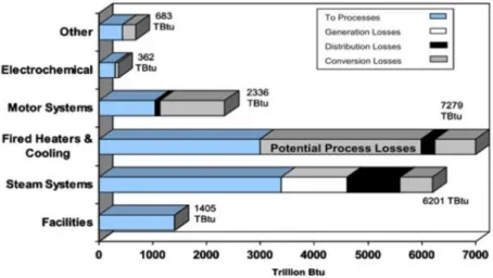
Numerous facts, such as the current energy crisis, its impact on the economy, the increase in the price of a barrel of oil, the decline in hydrocarbon and nuclear fuel reserves and the need to reduce air pollution put the energy issue at the forefront of global emergency. From an economic point of view, a reliable source of energy is essential for the industrial progress that underpins the economic development of any country [1]. Concerning environmental pollution, existing batteries to date have their own environmental issues, and their production and disposal present an environmental hazard. In 2001, Tanaka [2] showed that only 17% of primary and less than 5% of rechargeable batteries were respectively correctly recycled. At the same time, the energy needs of the industry (ENI) continue to increase and represent more than 1/3 of the total energy consumed (TEC) in the industrialized countries. For example, in 2014 the ENI in France was 19.2% (Energy balance), 70% in China [3] and 33% in the USA [4]. The problem that must be emphasized is that 20 to 50% of this consumption is dissipated by conduction, convection and radiation from hot equipment or in the form of hot smoke, as this is the case in the USA [5]. In France, for example, it is estimated that more than 27 TWh of heat whose temperature is between 100 and 200°C is lost each year [5]. In the United Kingdom, it is estimated that 14 TWh / year is recoverable, which represents 4% of its annual energy consumption [5]. Moreover, in an internal combustion motor, it is estimated that 75% of the thermal energy generated during combustion is lost through the motor equipment [6]. Thus, the recovery of heat energy lost in different fields (cf. Figure 1-1) such as power plants, industries, electric or thermal motors, electronic components an so on, is an invaluable way to reduce the energy crisis. Other energy sources such as vibrations, water flow and airflow could be harvested [7]. Nowadays, the harvesting and conversion of these energies present in the environment plays a prominent role in the fight for both the reduction of hydrocarbon consumption and the autonomous and continuous energy supply of MEMS (Micro-electromechanical systems) devices (such as mobile phone devices, remote devices etc.) to achieve a long operating time. Therefore, self-powered systems that harvest their operating energy from the environment hold great promise to power future portable and wearable electronics. Some conversion techniques of energies available in the environment and soil (like hydrocarbons) are summarized in the Table 1-1 and they depend on the type of energy.
Type of natural energy present in the
environment
Vibrations Oils Wind Heat
Conventional means of conversion Electromechanical Systems (EMS) Thermal motors with internal combustion Wind Turbines
Thermal Motors with External Heat input (TEEH) & thermoelectric materials (TEM)
Essentials components involved in harvesting
Mass, spring Cylinder, pistons Blades (helix)
Cylinder, pistons (for TEEH)
Essentials components involved in electrical
conversion
Coil & magnet or piezoelectric material
Coil & magnet Coil & magnet
Coil & magnet or a piezoelectric material (for TEEH) Table 1-1 : The energies present in the environment and their traditional techniques of exploitation.
These different machines or techniques used to recover these energies require a material or a combination of materials to convert them into electric energy. In fact, usually, energies from the environment are first converted into mechanical energy, and then into electrical one. To do so, conventional machines can rely on, for instance, electromagnetic systems (a combination of magnet and electric coil). Electric energy is particular, in the sense that it is not a primary energy, i.e. it requires another energy to produce it. In addition, it is, in turn, used directly to produce light or heat and can be converted into mechanical energy by powering an electric motor or can also be used to produce some chemical reactions.
Figure 1-1 : Estimation of energy losses for major energy use areas in manufacturing according to the U.S. Department of Energy (Industrial Technology Programs estimated by Energetics Incorporated) [8].
This lost thermal energy is divided into three categories, defined as follows [4]: • low temperatures when below 230 °C.
• average temperatures when between 230 and 650°C. • high temperatures when above 650 °C.
One way of harvesting this energy (lost otherwise) is the use of Stirling motors. For instance, cogeneration systems are commercialized, consisting of a conventional boiler that provides heat to homes and a Stirling motor coupled to it that recovers heat losses to convert it into electricity [9]. A working prototype of a portable micro motor, such as a miniature Stirling motor, capable to generate electric energy from any natural source of heat in the environment (or industrial heat losses) could interest various industries such as automotive, aeronautics, microelectronics and telecommunications ones.
The aim of this PhD was to design a prototype of a miniature Stirling motor that could be used for heat energy harvesting. First, the general context of this work will be presented. In the case of miniaturized machines, three main transduction mechanisms are used to obtain electric energy: piezoelectric, electromagnetic and electrostatic ones. Some harvesters based on mechanical vibration will be shortly presented in the section 1.2. a more detailed presentation will be given in appendix A. Then a focus on the Stirling motor will be proposed, followed by a literature review of some power generation and energy harvesting device at small scales.
1.1.
Context of the thesis
1.1.1. Project history and context
This PhD thesis, started in 2015, was part of the MISTIC (Micro STIrling Clusters for low temperature heat recovery) ANR (National Agency of Research) project, which started in January 2013, (duration: 42 months)1. The project’s partners were the SYMME institute (University of Savoie; project promoter), the FEMTO-ST Institute (University of Bourgogne Franche-Comté) and the UMI-LN2 institute (Universeurity of Sherbrooke). The project aimed to do a proof of concept of a Stirling micro-motor fabricated with MEMS technology’s batch fabrication for the recovery of waste heat at low temperatures in industrial thermal processes, with a specific architecture, based on a meso-scale (tens of centimeters) motor develop at SYMME institute (cf. Figure 1-2).
The use of MEMS technologies (collective structuring and assembling) was chosen, since it will allow the implementation of clusters of this type of machines (as illustrated on the left in Figure 1-3) to reduce the cost per electric Watt generated.
A preliminary work was to build the meso-scale machine to validate the feasibility. Therefore, in 2013, the first 6 months of the project were devoted to the modelling and identification of manufacturing strategies. This work led
to the production of an instrumented centimeter-scale Stirling motor (C-SE) at the SYMME laboratory, as shown in Figure 1-2. This motor architecture was inspired from a symmetric three-phase free-piston Stirling motor system developed by Der Minassians and Sanders (cf. Figure 1-4 [10].
Figure 1-2 : On the left : the meso-scale Stirling motor design [11] and below the description of one module. On the right: a) Global view of the experimental setup and (b and c) close up of the motor instrumentation [5].
Figure 1-3 : Concept and general design of the MISTIC project. On the left are clusters schema and on the right the schematic view of the Stirling micromotor.[Images From ANR project MISTIC]
This architecture has many advantages, such as technological simplicity and reliability (such as a multiphase double acting membranes avoiding friction losses). In the C-SE, the connection between membranes was ensured by mechanical links and experimental measurements were to be used to validate those made with the micro machine after its microfabrication. Therefore, at first, a new design for the C-SE instrumentation became mandatory and
had to be built. The global initial design of the micro-Stirling motor for the MISTIC project, with its constitutive parts, is given in the right part of the Figure 1-3.
At the beginning of this PhD thesis in november 2015, the main scientific outputs were that, at the University of Savoie, a design tool based on an equivalent electrical network analogy has been proposed and validated in relation to the experimental results of the meso-scale Stirling motor [11].
Figure 1-4 : Fabricated three-phase Stirling motor system of Der Minassians and Sanders [10].
Regarding the Stirling micro-motor, square membranes containing a liquid, with the aim of reducing their natural oscillation frequencies, have been designed, manufactured and dynamically characterized at the FEMTO-ST Institute [12]. A MEMS-based micro-regenerator to boost the Stirling micro-motor efficiency was also being designed and manufactured [13] at FEMTO-ST Institute.
1.1.2. Objectives of this thesis
The main objectives of this PhD were the design optimization, the microfabrication in the MIMENTO clean room facility and the characterization of the Stirling micromotor (based on the design given in Figure 1-3). Therefore, this work implies scientific and technological challenges linked to an motor size reduction.
Our contribution focused on all parts of the micro machine such as: a) The design part:
-
Improvement and optimization of the initial design of the membranes (shape, size, arrangement, resonance frequency):o Creation of a numerical model under COMSOL for the prediction of the stresses and the natural frequency of the membranes.
o Design of test specimens to characterize the mechanical properties of the elastic material of the membranes.
-
Introduction of the location of thermal regenerators (under development in the FEMTO-ST ENERGY department)-
Design of the micro chambers for compression and expansion of the membranes as well as their connecting channels.-
Designing the new ducts for the liquid filling (for the intermembrane connection) and assembly steps of the motor to avoid several technological problems related to the contamination of the equipments (availables in FEMTO-ST clean room) encountered with a former geometry.-
Identification of an efficient assembly technique and design of test samples b) The manufacturing part:-
Fabrication of membranes for necessary complementary tests-
Optimization of the membrane manufacturing process (repeatability, reproducibility) in a clean room.-
Manufacture of compression and relaxation chambers-
Integration and assembly, by the appropriate bonding methods, of all the constituent parts of the micro-machine (membranes, chambers, channels) to obtain the full micro motor.c) The characterization part:
-
Installation of thermal characterization benches (temperature resistance of membranes, etc.), dynamic (resonance frequency) and static (flexion or elasticity of membranes).-
Mechanical tests of membranes’s material properties with dedicated machines.The conversion part (mechanical motion into an electrical energy) was not the aim of this work. Thus we’ll only shortly begin by presenting the means to harvest and convert mechanical energy. Then we’ll focus on the Stirling motor principle followed by a literature review on works on miniature motor and/or harvesters.
1.2.
Vibrational Energy Harvesting and transducers
Vibration sources are an attractive option for the development of adequate power sources for low power supplying or for the autonomy of remote sensors and portable electronics. The typical vibration frequencies are between 20 to 100 Hz [14], [15] and acceleration values greater than 9.807 ms-2 are very rare in environment and industrial applications. The estimated harvestable power is in the micro to milliWatt range [16]. Energy transducers are materials, or combinations of materials, that convert energy into another form of energy (usually electrical). The main transducers to obtain electrical energy from vibrations are piezoelectric, electromagnetic and electrostatic. Piezoelectric materials are active materials that generate charges when mechanically stressed. Electromagnetic systems employ electromagnetic induction resulting from the relative movement between a permanent magnet (magnetic flux) and an electrical conductor as a coil. Electrostatic converters use the vibration-induced relative movement between charged plates (electrically isolated) against the electrostatic force to generate energy. Because of their low-cost manufacturing process, piezoelectric transducers, have often been proposed to implement easily exploitable energy harvester systems. But, solutions combining both electromagnetic and piezoelectric transducers were also explored to improve the energy density and the conversion efficiency [17]. Other solutions such as electrets or magnetostrictive materials have also been proposed for this purpose [18]. More details on the state of the art concerning all the converters above are presented in Appendix A.
Vibration-powered generators are generally constituted with inertial spring and mass systems (cf. Figure 1-5) employing the three main transduction mechanisms (piezoelectric, electromagnetic and electrostatic) to obtain electric energy from vibrations. A term commonly used to describe the adequacy between the harvester and its electric transducer is the coupling coefficient (kc), which connects the total input energy (Uin) with the output energy of the transducer (Ust) as follows:
𝐾𝑐 = √ 𝑈𝑠𝑡
𝑈𝑖𝑛 Eq. 1-1
From a practical point of view, the energy harvesters must deliver the minimum output mechanical power required by power converters (i.e. transducers) to operate with acceptable efficiency.
Figure 1-5 : Generic principle of vibration energy harvesting [7].
Thanks to the improved technology of MEMS, potentially integrable vibratory energy sensors exist with low power applications such as Wireless Sensor Network (WSN) nodes [16], [17], [19], [20]. Several energy harvesters in the literature used to have low output power and voltages, are large and bulky. But, fortunately, their efficiency is now turned to not peak only in a very narrow frequency range, thus making them suitable to scavenge energy from actual ambient vibrations. Research activities are currently oriented towards the improvement of the power
efficiency and the output power of the vibration energy harvester, to decrease the size of the transducers, the operating frequency to match the low frequency ambient vibrations. Moreover, knowing that ambient vibrations rarely occur at exact frequencies, their bandwidth widening is necessary to maximize the energy collection [21]. The vibrational energy harvesting mechanisms and architectural development in the recent years have been discussed. There have been many improvements on the designs (e.g. more compact, flexible, and wearable…). However, the main challenges, such as the wide bandwidth of ambient vibrations, make the vibrational energy harvesting systems with significant performances complicated to achieve. Development of MEMS system with low resonance frequencies are a real challenge.
1.3.
Stirling motors
Motors that can use heat energy (released from burning an energy-rich fuel like coal, gasoline, etc.) to make a gas expand, push a piston, drive a vehicle or factory machines wheel, are examples of heat motors. Heat (or thermal) motors can be classified into two types:
− Internal combustion motors (for example, Otto car motors): these motors burn the fuel and produce the mechanical power in exactly the same place inside the motor. In a car Internal combustion motor, it all happens in the rigid metal cylinders.
− External combustion motors (such as steam motors): In these types of motors, the place where the fuel is burned is completely separated from the place where the mechanical power is generated.
The Stirling motor belongs to the category of external combustion motors while remaining unique because it heats, cools and recycles the same gas (environmental friendly gas like air) to produce a useful mechanical power [22].
1.3.1. Principle and thermodynamic cycle
In 1824, Carnot developed a theoretical thermodynamic cycle whose effficiency is maximum [23]: a motor cycle, which is only valid theoretically and which consists of four successive transformations (reversible isothermal compression at a cold temperature (𝑇k), reversible adiabatic compression, reversible isothermal relaxation at a hot temperature (𝑇ℎ) and reversible adiabatic relaxation. The output of this cycle is the ratio between the useful output work (𝑊) and the input thermal energy (𝑄):
𝜂𝑐 = − 𝑊 𝑄ℎ= 1 − 𝑇𝑘 𝑇ℎ Eq. 1-2
For instance, with 𝑇ℎ = 500 K (230 °C) and 𝑇k = 293 K (20°C), we have a maximum yield of 41.7%. It should be noted that with these temperature levels, under no circumstances will it be possible to exceed this yield. The yield of Carnot, which constitutes the ideal case, makes it possible to compare the different systems of conversion of thermal energy to a theoretical maximum, and this even when the levels of the temperatures between these machines are different. It therefore serves as a reference for existing thermal machine technologies. Consequently, the efficiency (𝜂𝑟) of any thermal machine is the ratio between the yield of the considered motor (η)
and the yield of the Carnot cycle calculated at the same temperatures:
𝜂𝑟 =
𝜂
𝜂𝑐 Eq. 1-3
In the early 19th century (1816) during the Britain industrial revolution [24], Reverend Robert Stirling (Scottish pastor) invented the Stirling type motor (i.e. external combustion motor (cf. Figure 1-6)) when he was only 26 years old. The original patent number of 1816 was 4081 and was entitled "Improvements for Diminishing the Consumption of Fuel, and in particular an Motor capable of being Applied to the Moving (of) Machinery on a Principle Entirely New" [25].
This motor was invented well before the diesel motor (1893), the gasoline motor (1860) and the electric motor (1869), and it was, at that time, with the steam motor, almost the only possibility to convert heat into mechanical energy. Since steam motors are rather reserved for the great powers, the motor (2 Horse Power 1.5 kW) that he developed had a very important commercial success until the beginning of the 20th century in the field of low-power
motors [26]. Figure 1-6 presents the Stirling motor (a) and its working principle (b). The classical Stirling motor will be composed of two chambers (a hot and a cold one) usually separated by a heat regenerator component (to improve the motor yield).
If we consider the theoretical case of a perfect regenerator (i.e. a heat transfer without heat loss), the efficiency of the Stirling machine becomes equal to the yield of Carnot. Therefore, the invention of the regenerator by Robert Stirling has significantly improved the performance of its motor
Figure 1-6: The first Stirling motor, as specified in the 1817-1840 patents [25]. Coloration and annotation is added. In general, any Stirling motor contains at least two pistons (which do not necessarily have the same geometry) called according to their location (or their role) "displacer"-piston and "work-" or “power”-piston:
▪ The “displacer” piston is a piston (sometime with a little space between the edge of the piston and the cylinder wall depending on motor configuration) whose job is to move the gas between the heat source and the heat sink.
▪ The “working” piston or power piston (closely adapted to the cylinder wall), transforms the expansion of the gas into useful mechanical work that drives everything the motor feeds.
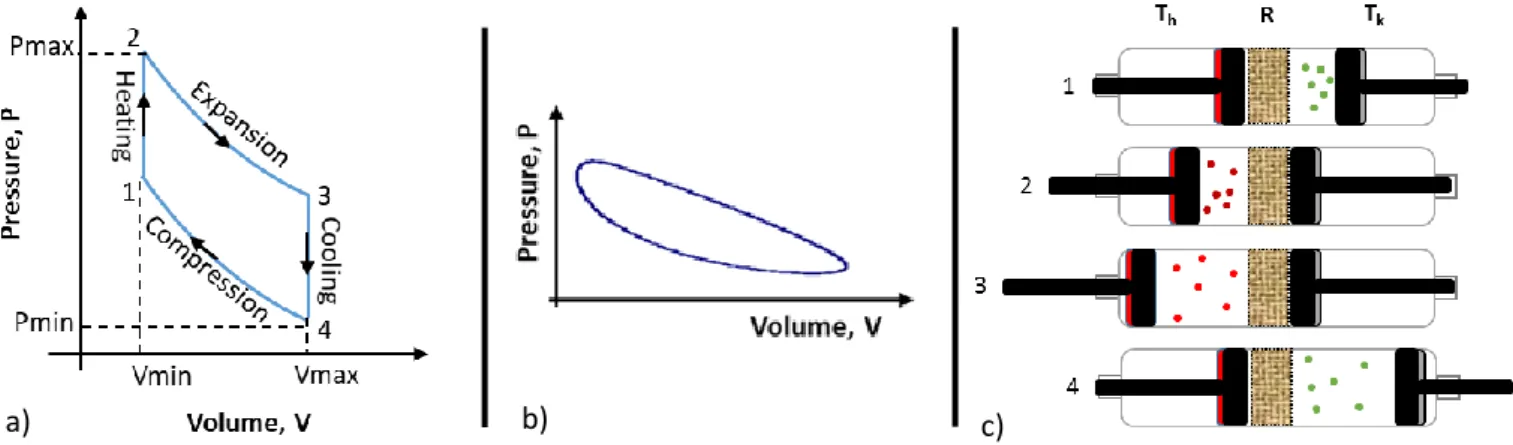
In conventional Stirling motors (Figure 1-6), pistons are usually connected to a heavy flywheel that allows the machine to operate smoothly. In operation, the two pistons move constantly, but they are out of phase. Generally, the displacer piston is in advance of 90° (i.e. a quarter cycle) in front of the working piston and they are powered back by the same flywheel. Being linked, the two pistons ensure that heat energy is repeatedly being moved from the heat source to the heat sink and converted into useful mechanical work. A Stirling motor converts thus heat energy into mechanical energy by repeating a series of operations, known as its thermodynamic cycle (cf. Figure 1-7 Figure 1-6c). The gas inside is alternately expanded and compressed, and in between, moving from a hot side (expansion side) to a cold side (compression side) and so on. The work piston (in red color Figure 1-6 b) is pushed by the pressure from the expansion of the gas to drive the flywheel, then it compresses back the gas so the cycle can repeat. The (gray) displacer piston displaces the gas from the hot side of the motor to the cold side (on the right) and so on. The theoretical thermodynamic cycle of the Stirling motor (cf. Figure 1-7 a), and c) for associated cycle) can be divided into four steps:
• 1-2 Isochoric transfert through the regenerator: the gas (shown by the red circles in Figure 1-6) is heated without volume variation at the hot end of the cylinder
• 2-3 Isothermal expansion : the heated gas has its pressure which increases until it expands. As the gas expands, it pushes the working piston, which, in turn, drives the flywheel. It is in this part of the cycle that the motor converts thermal energy into mechanical energy. In the ideal cycle, the expansion is assumed isothermal.
• 3-4 Isochoric transfert through the regenerator : The displacer piston thanks to the inertia of the flywheel brings the hot gas towards the cooled part. Before arriving in the cold part, the gas passes through the regenerator, it gives up some of its heat on the way at constant volume.
• 4-1 Isothermal compression : During this phase, the gas (shown by the green circles) is at the cooled cylinder. The piston compresses the gas while its heat is removed by the heat sink. Thanks to the flywheel's inertia, the displacer piston brings the cold gas back to the hot part of the machine. Before reaching this
part, the gas (at constant volume) heats as it passes through the regenerator, the latter gives up part of its stored heat from the previous phase of the cycle.
In theory, it is considered that the expansion and compression phases are isothermal and that the thermal phases (i.e. heating and cooling) are isochoric. In fact, the four steps are not physically separated but merge into each other. Although the motor goes through a cycle, it is not a symmetrical process: heat energy is constantly removed from the hot source and released at the heat sink and the real Clapeyron diagram is modified as shown in Figure 1-7 b).
Figure 1-7: Clapeyron diagram Pressure-Volume diagram of a) an ideal Stirling motor cycle. b) a real cycle of a Stirling motor. c) Simplified working principle of a Stirling motor, the subscripts “h” and “k” will respectively stand for “hot “ and “cold” and the letter “R” on the figure is for the regenerator, “c” and “e” will represent respectively the compression and the expansion. That happens because the hot gas when it expands does a certain amount of work on the work piston, but the piston does not do the same work when compressing the cooled gas and returning it to the start point [27], [28]. Those differences between real and ideal cycles are mainly due to the following facts:
• The heat exchangers and the regenerator are not perfect.
• Dead spaces exist (volumes not swept by the pistons) in the actual motor.
• The synchronization of the pistons is not discontinuous: it is often approached by a continuous sinusoidal movement
• The gas flow dissipations and frictional drag generate pressure drop.
• The viscous dissipations in the different components of the machine primarily in the regenerator cause mechanical power loss.
• Mechanical losses such as vibrations are present
• Seal leakage through the rings results in a loss of gas pressure. • Gas spring effects generate hysteresis losses.
• Heat conduction happens through the walls and from the hot side to the cold side of the machine. When you apply mechanical energy into a Stirling motor and run it backward, the motor will effectively remove heat from the heat sink part of the motor and will expel it towards the part that should be heated. That turns a Stirling motor into a very efficient cooling device ("cryocooler") [29]. Due to the high efficiency achieved by Stirling macro machines for cooling, Stirling micro chillers are a potentially interesting alternative for small devices cooling. This cooling mode will be studied in chapter 5.
1.3.2. Stirling motor architectures
1.3.2.a.
Mechanical connection of pistons
There are several Stirling motor architectures, the most classic being able to be considered as the types Alpha (α), Beta (β) and Gamma (γ), and distinguished as follows [30]:
• Alpha motors (cf. Figure 1-8) have two separate cylinders in each of which is a piston. Variations in hot (expansion space) and cold (compression space) volumes are created separately by separate piston
movements. Their main advantage is the possibility to assemble several Alpha motors to give rise to compact configurations (multicylinders motor) that provide more power.
Figure 1-8: Alpha type Stirling machine configuration (left) and it simplified view (right). (https://www.ohio.edu/mechanical/stirling)
• Beta type motors (cf. Figure 1-9) designate a single-cylinder arrangement. The displacer piston, and the working piston, move together linked by a crank shaft mechanism. Variable hot and cold volumes are created by the combined action of the two pistons.
Figure 1-9: Beta type Stirling machine configuration (left) and it simplified view (right). (https://www.ohio.edu/mechanical/stirling)
• Gamma type motors (cf. Figure 1-10) have two cylinders like the Alpha type but variable hot and cold volumes are created as for the Beta type. The Gamma type has more dead space, which reduces its specific power.
Figure 1-10: Gamma type Stirling machine configuration (left) and it simplified view (right). (https://www.ohio.edu/mechanical/stirling)
There are several types of drive systems that ensure the appropriate movements of the working gas to achieve the Stirling cycle [31], [32], [33]. The Stirling motor can operate from a linked kinematic chain or free pistons type version.
1.3.2.b.
Linked kinematic chain
The standard links use conventional mechanical elements such as cranks, connecting rods, flywheels. Standard Kinetic drive mechanisms are crank-slider drive, rhombic drive, swach-plate drive, Ross-Yoke drive (diagrams can be found in [31].
Figure 1-11: Compact multiple cylinder configuration of Alpha Stirling Motors. (https://www.ohio.edu/mechanical/stirling/) There are other categories of Stirling machines. The multiphase architectures (multicylinder) where a piston have a double action ; plays the role of power piston and displacer for two Alpha Stirling motors connected. This system consists of several Stirling motors assembled in series. Figure 1-11 is a diagram illustrating the concept. One of the essential aspects of these motors is to have imposed kinematics, namely that the piston stroke and the phase shift are fixed by specific mechanical elements [5].
1.3.2.c.
Free-piston Stirling motor
In a free-piston Stirling motor, reciprocating pistons are coupled to springs and move entirely in response to spring forces (gas, membrane or mechanical spring) acting upon them. Invented by Beale [34] in 1969, a Free-piston Stirling motor is a dynamic resonant system. The operating frequency is determined by the stiffness provided by the springs and the mass of the moving elements. Although this system seems mechanically simple, free-piston Stirling motor is the most difficult and complicated to put into practice [31].
The main characteristics of free-piston Stirling motors are : • It is a resonant system operating at a constant frequency.
• A self-starting capability. When it is heated up, the system changes into an unstable equilibrium state and starts to oscillate automatically at a natural frequency without any requirement for external excitation. • The displacements of moving pistons change accordingly with the mass. If more loads are added, the
displacements decrease.
• Pistons move linearly inside the cylinders.
• The requirement for lubrication is ensured by the working gas rather than oil. Oil-free operation of the motor eliminates the problem of regenerator contamination.
• Motor cylinders are hermetically sealed thereby eliminating entirely the problems of dynamic seals of kinetic Stirling motors.
• Motor operation is quieter and more stable compared to kinetic Stirling motors.
If the piston in a free-piston Stirling motor is replaced by a diaphragm, the mechanical friction and wear are eliminated. This type of special free-piston Stirling motor is called the diaphragm Stirling motor, invented by Cooke– Yarborough in the 1960s [35] as a power generator with a substantially higher efficiency than thermoelectric systems at the time [35], [36]. To date, the disadvantage of diaphragm Stirling motor is the low power density because of the much smaller swept volumes of diaphragms compared to those of pistons.
To model a Stirling machine, there are numerical models that we will briefly introduce in the next section. However, for more information and details (on the calculations for example) we invite the reader to consult the appendice A.
1.3.3. Modeling the operation of Stirling motors
There are generally four theoretical approaches to modeling Stirling motors. These different theoretical analyzes are classified according to a concern of increasing accuracy with respect to the actual operation of the machine. The first model, which is the simplest because approximate, is the zero-order analysis. The second model is the first order one and is based on the isothermal analysis developed by G. Schmidt [37]. The second order, which is a little complex, includes the calculation of the various losses assumed to be decoupled (i.e. separately calculable from each other). Last, the most complex is the third-order analysis or "coupled analysis". In this work, only the zero, first and second order method are detailed below. More informations on the more complex approach can be found in [28] and more details on the simple approaches listed above are presented in appendices.
There are other 1st order modelling methods in the literature that consider Stirling engine losses. These methods are based on the theoretical cycle but they allow obtaining results closer to reality than the Schmidt model. One example is the TDF (Thermodynamics in Finite Physical Dimensions) method [38] in which thermal and mechanical losses are individualized, thus making it possible to quantify them during actual engine operation. There is also the so-called direct method [39] allowing, through adjustment coefficients, to take into account the different losses of the Stirling engine during operation.
1.3.3.a.
Zero order analysis
Based on experimentally obtained results, the zero-order analysis developed by William Beale during the 1970s [33], makes it possible to determine corrective coefficients for the theoretical formulas. According to Beale [34], when considering a Stirling machine running in the motor cycle, its mechanical power Wm could be expressed by the relation (Eq. 1-4).
𝑊𝑚 = 𝐶𝑡. 𝑃𝑐𝑦𝑐𝑙𝑒. 𝑓. 𝑉𝑠𝑤𝑐. 𝑓(𝑇) Eq. 1-4
With Ct a constant depending on the system, Pcycle the pressure over a cycle , f the frequency, VSWC the swept volume in the compression chamber and f(T) a function of the temperature.
Around 1980, Walker ( [40]) based on several practical tests on Stirling machines, proposed the following formulation of Beale's initial formula:
𝑊
𝑚= 0.15 𝑃
𝑐𝑦𝑐𝑙𝑒. 𝑓. 𝑉
𝑠𝑤𝑐 Eq. 1-5In general, the Beale formula is used in optimizing the choice of the temperature regime. Its formula has been widely used by Senft (1982) [41], West (1986) [42] and Organ (1992) [43]. These scientists validated it by including the effects of the temperature ratio. According to West [42], Beale's formula should be modified as follow:
𝑊𝑚 = 0.25 𝑃𝑐𝑦𝑐𝑙𝑒. 𝑓. 𝑉𝑠𝑤𝑐 𝑇ℎ−𝑇𝑐
𝑇ℎ+𝑇𝑐 Eq. 1-6
For Stirling machines operating in a cooling cycle (cryogenic), Walker in 1983 [32] (based on the Beale formula) establishes an expression to approximate the cooling capacity of a Stirling machine based on the analysis of experimental results :
𝑄𝑐 = 10−6𝑃𝑐𝑦𝑐𝑙𝑒. 𝑓. 𝑉𝑠𝑤𝑐𝑇𝑐 Eq. 1-7
Results such as thermal efficiency and power, obtained from these formulas, are estimates that can only give an order of magnitude in pre-studies for a Stirling machine design. In fact, this Beale analysis is about an ideal Stirling machine, the results are not realistic because there are very important differences between the ideal Stirling cycle and the actual operation of a Stirling machine.
1.3.3.b.
First order analysis or Ideal Isothermal Analysis
The first order analysis (or isothermal), proposed by Gustave Schmidt in 1871 [37], makes it possible to estimate the mechanical power of an motor as well as its performance. It is often the basis of pre-studies of the Stirling motor. In Schmidt's model there are assumptions:
• The movement of the pistons is sinusoidal and their oscillation frequency is constant. • The evolution of compression and expansion phases are isothermal.
• The gas is ideal so the ideal gas state equation is applicable. • The regenerator is perfect (infinite heat capacity).
• The mass of injected gas is constant and its instantaneous pressure is uniform (no leakage) so that the conservation of the mass applies.
• The thermal equilibrium conditions are then assumed to be established. There is no mass accumulation inside a chamber.
Figure 1-12 : Schematic view of the zones and cells of the isothermal model [28] extracted from https://www.ohio.edu/mechanical/stirling/ swe h swc swe k h V sin T arctan V V cos T T = + 2 2 swe swc swe swc h k h k
1
V
V
V
V
c
2
cos
2
T
T
T
T
=
+
+
(
)
h k clc swc k h cle swe r k k k h k h h hT
ln
T
V
V
V
V
V
V
s
V
T
2T
T
T
T
T
T
2T
=
+
+
+
+
+
+
−
andb
c
s
=
Schmidt number(
)
(
)
2 swc swe sw sw1 b
1
V
V
Sc
sin
sin
b
V
V
− −
=
+
−
Mean pressure (with r =R/M) mean
2 m r P s 1 b = − Work in the compression and expansion
chambers W=S Pc meanVsw
Power W=W f
Heat transferred over a complete cycle on the expansion chamber (equal to the work done in
the expansion chamber)
(
)
(
2)
e swe mean 1 b 1 Q V P sin b − − = − Efficiency e W Q = Table 1-2: Parameters and expressions for isothermal analysisBased on the first order analysis, the Table 1-2 presents the main equations describing the performances of a Stirling motor (more details concerning the equations determination are given in appendix B). The letters c, k, r, h and e respectively designating the compression chamber, the cold exchanger, the regenerator, the hot exchanger and the expansion chamber (cf. Figure 1-12 and Figure 1-8). The known data are the volumes of the cold space Vk, of the regenerator Vr, of the hot space Vh and the temperatures of cold space Tk and hot space Th. The swept volume in the compression and expansion chambers are respectively denoted Vswc and Vswe. α is the phase shift between the piston and the displacer. This angle represents the phase advance of the expansion space volume variations with respect to the compression space volume variations. R and M are respectively the ideal gas constant and the molecular weight.
1.3.3.c.
Second order analysis or Ideal Adiabatic Analysis
This analysis allows to determine the effects of the adiabatic operation of the compression and expansion spaces on the motor performance and to examine the detailed behaviour of the relevant variables across the cycle (temperature ratio, phase angle, swept volume ratio, ratio of dead space). This model (cf. Figure 1-13 for a schematic view of the parameters) is more realistic for estimating the mechanical power of an motor as well as its performance from its geometry.
Figure 1-13: Schematic view of the zones and cells of the adiabatic model [28], extracted from https://www.ohio.edu/mechanical/stirling/
The advantages of this analysis are that the amount of heat transferred to the regenerator is estimated and the method may include heat transfer and friction flow analysis of the heat exchangers. The disadvantage is that this analysis leads to nonlinear differential equations that can only be solved numerically. A detailed presentation of this model, that was not used in this PhD (due to the number of unknown variables), is given in the appendix B. To conclude on this part, Stirling motor can be used, for instance, as motorization motor; as cooler or heat pump, as heat harvester etc. In this present work, it is this last application we will focus on. Classical Stirling motors are usually macro-size or (more rarely) meso-size. Nowadays, many devices in the millimeter scale range are being fabricated using MEMS batch-manufacturing techniques with low unit cost characteristics [44], [45] and rapid prototyping, with basic materials such as silicon and glass that are like those used in the integrated circuit/microchip industry. Although initially the micro-devices fabricated using MEMS were sensors and actuators, recently more complex mechanical devices such as micro-coolers, pumps and motors are being developed. Indeed, a miniaturized device, even with a moderate conversion efficiency (of heat or hydrocarbon fuels into electric energy), would indeed increase the lifetime and reduce the weight of an electronic or mechanical system often powered by heavy batteries [46]. Moreover, the numerous advantages related to the miniaturization of electromechanical systems such as their use in isolated locations that are difficult to access (for example in space or in the deep sea) have increased the need to produce microgenerators of power (milliwatts to watts) which are not bulky, have low weight and long lifetime. Since thin films batteries are still in development and are not sufficient (~ 1 kJ / g) to sustain small device’s power requirements during long periods [47], producing miniaturized power-generation devices opens exciting new opportunities, especially in the field of everyday-devices size reducing and sophistication. Improvements in this area can make possible new applications and/or capabilities.
On the next sections, we will present a literature review on heat generation and harvesting methods at small scales: first for miniature motor with internal combustion/heat source, then for miniature motor with external combustion/heat source. Knowing that we are trying to manufacture a micro machine to convert thermal energy
![Figure 1-2 : On the left : the meso-scale Stirling motor design [11] and below the description of one module](https://thumb-eu.123doks.com/thumbv2/123doknet/14694461.745890/17.892.121.776.199.696/figure-left-scale-stirling-motor-design-description-module.webp)
![Figure 1-16 : a) Integrated catalytic combustor/ thermoelectric micro-power generator developed at the University of Michigan [46]](https://thumb-eu.123doks.com/thumbv2/123doknet/14694461.745890/30.892.118.762.738.934/integrated-catalytic-combustor-thermoelectric-generator-developed-university-michigan.webp)
![Figure 1-18 : a) EDM technologies steel fabricated mini-rotary motor with a 10 mm rotor [46], [59]](https://thumb-eu.123doks.com/thumbv2/123doknet/14694461.745890/32.892.126.772.426.590/figure-edm-technologies-steel-fabricated-rotary-motor-rotor.webp)
![Figure 1-22 : a) Turbo-shaft setup. b) Schematic view of the compressor and turbine. c) Compressor (left), turbine (right) and air bearing insert (Rotor diameter: 20 mm- Size compared to 1 euro coin) [81]](https://thumb-eu.123doks.com/thumbv2/123doknet/14694461.745890/34.892.110.770.279.496/figure-schematic-compressor-turbine-compressor-turbine-diameter-compared.webp)
![Figure 2-1: Schematic view of the MISTIC free piston multi-cylinder double acting microStirling motor [107]](https://thumb-eu.123doks.com/thumbv2/123doknet/14694461.745890/47.892.224.665.375.607/figure-schematic-mistic-piston-cylinder-double-acting-microstirling.webp)
![Figure 2-5: Dead spaces in a classic Alpha Stirling machine symbolized by Vclc, Vcle, Vh, Vk and Vr (Extracted from https://www.ohio.edu/mechanical/stirling/ and [28])](https://thumb-eu.123doks.com/thumbv2/123doknet/14694461.745890/51.892.148.719.629.898/figure-classic-stirling-machine-symbolized-extracted-mechanical-stirling.webp)