Science Arts & Métiers (SAM)
is an open access repository that collects the work of Arts et Métiers Institute of
Technology researchers and makes it freely available over the web where possible.
This is an author-deposited version published in: https://sam.ensam.eu
Handle ID: .http://hdl.handle.net/10985/9061
To cite this version :
Eric BECKER, Régis BIGOT, Laurent LANGLOIS - Thermal exchange effects on steel
thixoforming processes - The International Journal of Advanced Manufacturing Technology - Vol. 48, n°9-12, p.913-924 - 2010
Any correspondence concerning this service should be sent to the repository
Thermal exchange effects on steel thixoforming processes
Eric Becker&Régis Bigot&Laurent Langlois
Abstract Steel thixoforging is an innovative semi-solid forming process. It allows the manufacturing of complex parts and minimises the forming load. This work aims to identify and characterise the main feature zones of a thixoforging part. The material flow and the forging load are dependent on the thixoforging speed, the tool temperature and the initial temperature of the slug. The data are obtained for C38 thixoforging steel. A specific extrusion tool was designed that integrates the heating of the tool and the slug. This tool was set up on a high-speed hydraulic press. This work highlights the effects of heat exchange on the microstructure, the internal flow and the mechanical characteristics of thixoforging material. These heat exchanges depend primarily on the working speed and tool temperature. The internal flow is composed of three distinct zones. Among them, only semi-solid zone is observed during working. The microstructures of thixoforming C38 steel consist of ferrite, pearlite and bainite.
1 Introduction
The manufactures always seek to minimise production time and manufacturing costs while maximising the quality of their products. This approach is also valid for the metal forming industry; the consequences of that are
& An increase of the material properties in the hot stamping domain [1]
& Important springbacks in cold stamping [2]
& Design of new manufacturing process related to the development of new alloys [3]
& Manufacturing of blanks, near net shape or net shape parts [4,5] and reduction material ratio billet/part [6,7] In this context, two innovating forming processes, thix-oforming and thixocasting, were developed. They allow manufacturing parts with complex shape and high mechanical properties. They also minimise the numbers of step involved in manufacturing process [8–10]. The objective is to obtain parts combining the advantages of casting and forging processes: & The casting using the properties of fluidity of molten
metal alloys makes it possible to obtain blanks of complex form in only one stage. The main defects of the manufactured parts are porosities and consequently weak mechanical properties.
& On the contrary, forging provides parts with high mechanical characteristics but often requires numerous stages to obtain the final part.
These two processes use the semi-solid state of material. In thixocasting, semi-solid state is reached by partial solidification of the molten metal, while in thixoforging it is reached by partial fusion of the solid [11]. The forming of aluminium alloys, by thixoforging and especially by thix-ocasting, is rather well controlled and industrialised [8–10]. In the case of steel thixoforging, difficulties lie in:
– The high forming temperature
– The mechanical and thermo-mechanical behaviour of the semi-solid steel is not well defined.
The presented work has the aim to collect data for better comprehension of the steel behaviour during thixoforging process. The collected results will help in implementation of the original two phase multi-scale“micro–macro” model [11–14] in Forge 2008® in 2D and 3D version.
Major C38 steel thixoforging experimental results are presented in this paper. So future works can use this E. Becker
:
R. Bigot (*):
L. LangloisArts et Métiers Paristech, CER de Metz,
Laboratoire de Conception, Fabrication, Commande, 4 rue Augustin Fresnel,
57078 Metz Cedex 3, France e-mail: [email protected]
experimental data (macro- and micrographies) concerning thixoforged parts. The first part of this paper presents experimental data on heating system, material, tool and forming press. Impacts of forming parameters on part geometry and forming load [15,16] are studied.
The second part is related to heat exchange impact on part versus experimental parameters, i.e. forming speed, die temperature and initial slug temperature. Some mechanical results are presented before discussions and final analyses about thixoforging flow in steel part.
2 Experimental data of thixoforging steel
This paragraph describes the experimental details of the tests, which were performed in order to study the influence of forming speed, tool and initial slug temperature on steel thixoforging. Specific tools were designed to minimise the dynamic defects of the press and to possibly remove the transfer time of the slug towards the tool. The control of the heating is also important to obtain homogeneous temperatures in the slug while minimising the cycle time. 2.1 Experimental device
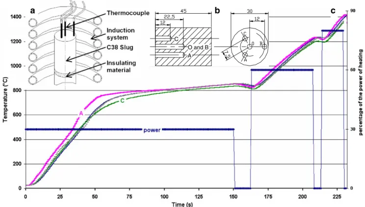
In this work, in order to identify and quantify the key parameters influencing thixoforging, a forward extrusion test is performed. It consists of thixoforging a cylinder of diameter 30 mm to the diameter 40 mm and to reduce it at once to 12 mm (Fig.1). The forming process is made of two stages:
– First, the slug fills simultaneously the cylinder with diameter 40 mm and the entrance cone (Fig.1b).
The slug is then extruded in the cylinder of diameter 12 mm (Fig.1c, d).
The die is at room temperature or can be heated at 400°C using a heating resistance rolled up around the tools. This heating resistance moves with the die during forging.
In this configuration, the die is fixed on the upper part of the hydraulic press. The slug is posed on a punch, fixed to the hydraulic press. The test is thus a backward extrusion.
The stop of upper die of the high-speed hydraulic press (vMAX=750 mm s−1) is not instantaneous because of its
inertia. Thus then the metal is still being deformed while the speed decreases. In order to avoid this problem, a shock absorption system of the punch was developed and integrated into the tools. This device consists of shock absorbers and guide. It is placed on the press table and supports the punch (Fig.2). This active part of the tools is also made up of two tubes, which will transmit the press loading. The superior tube is fixed on the press tool axis, and the inferior one is fixed on the damper system. When the two tubes come into contact, the thixoforging is finished (Fig. 2 c, step 5). The damper table does not move before the tube contact. Displacement after contact (yBon Fig.2c,
step 5 and 6), which corresponds to the deceleration stage of the press, is absorbed by the dumper system (Fig. 2 c, step 6).
This tool is instrumented with load and displacement sensors. The load sensor is placed under the punch and measures only the extrusion load exerted on the thixoforged part. Friction and heat exchanges of the active parts of the die are improved by pulverising a ceramic particle layer. This last one decreases friction and acts like heat insulator between the tool and the hot parts [17].
b c d 40mm 12mm 30˚ 30mm a
Fig. 1 a–d Part at different stages of the thixoforging extrusion
Heating of in situ piece
Tool Approach Descent of the upper
plane (yA)
End of the heating Start of forming Displacement of the tool axis
Thixoforging End of thixoforging
The tube are in contact
Stop of the tool axis Compression of the
dampers (yB)
Step 1
Step 2
Step 3
Step 4
Step 5
Step 6
y
Ay
Ba
b
c
Fig. 2 Complete extrusion device set up on the press (a and b) and various steps of the extrusion operation (c)
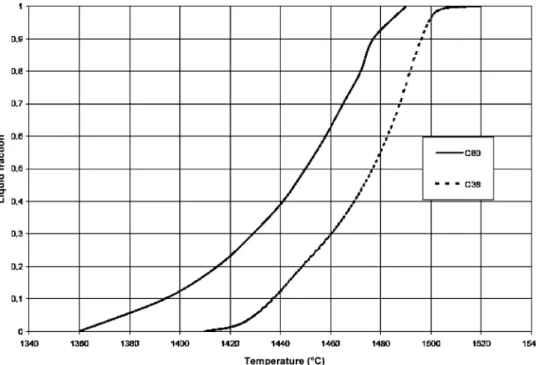
Fig. 3 Liquid fraction curves for different steels as a func-tion of temperature
2.2 Slug
The slug is characterised by two major parameters: its geometry and its steel grade. The height of the slug should not be too large in order to avoid its collapse under its own weight. This depends on the liquid fraction of the slug. The choice of the steel grade for a semi-solid forming is essential. In order to increase the thixoforgeability, it is necessary to choose a steel, which has melting point as lower as possible and which has fusion temperature range as larger as possible. Thus it is possible to obtain a liquid fraction not very sensitive to a temperature variation within the slug. Differential calorimetric analysis and differential calorimetry scanning allow to evaluate these two aspects. Figure 3 illustrates the decreasing of steels melting point according to the increase in the carbon percentage and also in the associated elements of addition [17–20]. These elements also influence the interval liquidus–solidus and give the possibility of increasing the reliability of the process of thixoforging. Steel grades can thus be developed not only according to the thixoforgeability [17,21] but also according to the specifications of the product.
It is important to note that differential scanning calorimetry (DSC) analysis is carried out at lower heating rates (20°C min−1) than induction heating rates classically implemented in thixoforging (100–900°C min−1). Thus,
the kinetics of solidification and fusion is not the same. It makes it difficult for evaluation of the exact liquid fraction in the case of high-speed heating from DSC curves. Thus, in this article, in order to avoid the difficulties of determination of the liquid fraction, only the heating temperature of the slug and its steel grade are mentioned. The reader will be able quickly to realise that thixoform-ing process is obtained with a fraction of liquid lower than 30%, according to DSC curves. In this work, only C38 steel is tested (Table1); the temperature of solidus is 1,410°C and the temperature of liquidus is 1,490°C (Fig. 3). Former works of Rouf [12] and Cézard [17] show that the induction heating of a laminated steel allows its thixoforging forming, and a spheroidization of the material is not necessary.
The slugs have a diameter of 30 mm and height of 45 mm and are extracted from a laminated bar.
2.3 Heating mode
The heating of the slug is carried out using an induction heating of a maximum power of 100 kW and of a
frequency close to 100 Hz. In order to obtain a homogeneous slug temperature, heating cycles consisting of several power stages separated by dwell time are used (see Fig. 4 a). The parameters of the heating process are determined experimentally with an instrumented slug as shown on Fig.4 b.
To control the initial temperature of the slug at the beginning of the forming process, the induction heating is integrated into the tools, limiting the heating losses due to the slug transfer towards the tools (Fig.2).
2.4 Influencing thixoforging parameters
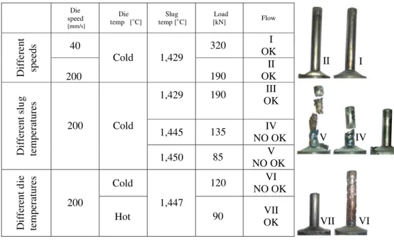
After having performed greater number of tests (more than 16), it was identified that the tool speed, the initial temperature of the slug and the temperature of the tool have dominating influence on the nature of the material flow and the forming load. Figure 5 illustrates typical evolution of forming load versus time and the maximum load determination on experimental curves. Table 2 illus-trates the influence of these parameters as a synthesis of the former works.
These parameters mainly affect heat exchange between die and part. This influences the forming slug temperature and as a result its liquid fraction and therefore, the viscosity and consistency, the desagglomeration of the solid skeleton, the forming load, the type of flow and finally the microstructure of the thixoforged parts and its mechanical properties.
3 Impact of heat exchange on thixoforged part
This part article presents an investigation of the heat exchange impact by macro- and microscopic analysis of parts obtained under various thixoforging conditions. These analyses are correlated to mechanical testing (microhard-ness and tensile test).
3.1 Illustration of the heat transfer influence by numerical approach
The numerical simulations, shown in Fig. 7, are carried out using the software Forge 2008® with the original multi-scale model micro–macro, the friction law of Tresca (m = 0.45), a homogeneous heat transfer coefficient on all the surface of the tools of 10 kW m−2K−1, an initial slug temperature of 1,430°C and initial tools temperature of
C Mn P S Si Al N Ni Cr Cu
0.418 0.751 0.010 0.021 0.19 0. 021 0.065 0.077 0.144 0.133
Table 1 Chemical composition of C38 steel (wt.%)
400°C. Two values of the tool speed are considered, 50 and 200 mm s−1.
For the lower die speed, heat exchange between the tool and the part is naturally more important, especially in the entrance cone where the contact time is longest. The only aim of these simulations is to reinforce the experimental methodology developed during this work and to prepare future works by exploiting multi-scale micro–macro model [14,22,23].
3.2 Macroscopic analysis of the thermal affected zone Figure6is defined by a number that represents the position of the various points which can be studied on an axially cut of thixoforged part. These locations are used for micro-hardness and micrographies in this study.
Figures 8 shows the macrographies obtained by HCl etching of two samples thixoforged under different con-ditions (minimal/maximum speeds, initial temperature of
Fig. 5 Experimental data of load versus displacement and identification of maximum load (Vdie=200 mm s−1, Tdie=30°C) O and B A C
a
b
c
the slug and tool temperature) and thus with different heat exchanges. Three areas (called A, B and C on Fig.8a) can be observed for each sample. Table 3 presents the macrographies (Bechet–Beaujard etching) obtained in these three zones for all the samples.
For the sample 40CM, extruded with strong heat exchange, the zone A exhibits a weak flow, and the material remains in contact with the tool and is cooled quickly (40CM point 13 Table3). A part of A is deformed (40CM point13 Table 3) and is extruded. During the forming process, area B contains an amount of semi-solid metal that is useful to feed the whole shape. Area C illustrates the axial flow similar to traditional forging process (items 4, 6 and 9, Table3).
For the extrusion specimen in low thermal exchange conditions, area D is identical to area A, except that its thickness is lower. This confirms the numerical simulation conclusions. Metal from area E forms waves during the yield, and material is semi-solid during the whole forming process. Area F illustrates an axial flow on a part of the extruded area.
The difference thickness between area A and D corre-sponds to a much more important and deeper solidification due to a high level of thermal exchange between die and slug. This can also be observed in Figs.7and8. Some high thermal exchanges exist too in area F and at the end of area C, and they explain this typical forging yield. Then, a high gradient is created between the inside and outside of the part, leading to a semi-solid heart during the whole forming process (points 19, Table3). Area E keeps its semi-solid properties, surrounded by a material having solid-type behaviour.
The macrographs of the points 4, 6 and 9, located in area C or F, confirm a material flow identical to that of traditional forging. The area F of the sample 200CH is rather smaller and does not excess point 6. Beyond this, there is a zone in which steel contained liquid during the whole forming process.
All the macrographies at point 10 show a limit between the two areas A and B or D and E. The first area was solidified very quickly as it was in contact with the “cold” die but also because it corresponds to the initially coldest part of the slug. Area B or E do not exhibit axial fibre but Table 2 Influence of speed, slug temperature and die temperature on steel thixoforging
Die speed [mm/s] Die temp [o o C] Slug temp [ C] Load [kN] Flow 40 320 I OK Diffe rent speeds 200 Cold 1,429 190 II OK 1,429 190 III OK 1,445 135 IV NO OK Differ ent s lu g temperatures 200 Cold 1,450 85 V NO OK Cold 120 VI NO OK D if fer ent d ie temperatures 200 Hot 1,447 90 VII OK II I III IV V VI VII
Fig. 6 Localization of the stud-ied points of the samples
radial undulations, those that correspond to a semi-solid material with a fluid behaviour. The line separating area A and B or D and E is located close to the surface of the part when heat exchanges are weak. This is the case of the sample 200WH obtained for a speed of 200 mm s−1with heated tools.
All macrographies at point 13 indicate that the material flow in this area was weak and that solidification was fast due to the contact with the cold tool and lower initial slug temperature. For specimens extruded with cold tool, 40CM and 200CH, one can observe lines corresponding to the orientation of the structures of the rolled slug before thixoforging. These areas are deformed by the flow of semi-solid area B, which curves them towards the reduction of diameter.
3.3 Microscopic analysis of the areas
The forming speed and the tool temperature have influence on the metallurgical structure of the part. The micro-structures at the different points of the samples are shown Fig.9. They are revealed by a nital (nitric acid 3%) etching.
3.3.1 Grain size
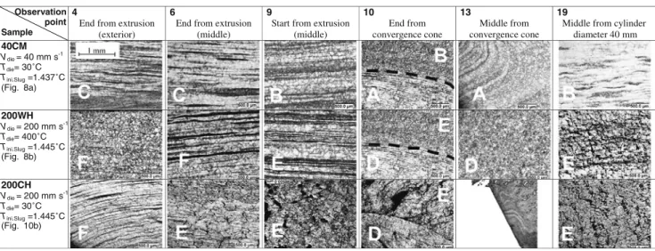
Grain size changes with respect to different position in the part and depends primarily on the temperature of the tool. Also the structures are close to the hot zones (along the axis of symmetry and in the zone B or E), and during forming process more grains are large. The areas that are cooled less quickly exhibit nucleation of large grains. In the same way Table 3 Bechet–Beaujard macrographies at several points of thixoforging parts under different conditions
Observation point Sample
4
End from extrusion (exterior)
6
End from extrusion (middle)
9
Start from extrusion (middle) 10 End from convergence cone 13 Middle from convergence cone 19
Middle from cylinder diameter 40 mm 40CM Vdie = 40 mm s-1 Tdie= 30˚C Tini.Slug =1.437˚C (Fig. 8a) (Fig. 8b) (Fig. 10b) 200WH Vdie = 200 mm s-1 Tdie= 400˚C Tini.Slug =1.445˚C 200CH Vdie = 200 mm s-1 Tdie= 30˚C Tini.Slug =1.445˚C
Fig. 7 Temperature distribution in part test for two die speeds (thermal exchange coefficient 10 kW m−2)
the heated tools limit heat exchange between the part and the tool and, thus, support the nucleation of large grains in the contact zone.
The initial temperature of the part does not have a great influence on the grain size, and few differences are observed. The grain size seems to be slightly more important for a higher temperature.
3.3.2 Type of structure
In areas A or D at points 13 and 14 and at the end of the zone C or F, there is more ferrite than everywhere else, and this corresponding to a decarburization. During heating, the slug surface decarburised as it is in contact with the atmosphere. Decarburization is all the most important as the heating temperature is high. Area A, D, C or F is fed by these external and decarburised slug areas.
3.4 Impact of heat exchange on the mechanical properties 3.4.1 Hardness
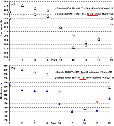
Extruded part hardness is analysed by Vickers hardness tests under a 3-kg load. Figure 10 shows a summary of experimental hardness results.
The Vickers hardness decrease at points 13 and 14 illustrates a low cooling speed after the forming (the slug is cooled into the dies) or a chemical gradient of the slug. Micrographs are confirmed by high ferrite grade of decar-burised area that it is not very sensitive to the cooling speed. The variation of the Vickers hardness is less important when the forming speed is higher than 200 mm s−1 as compared to case-forming speed 40 mm s−1(Fig. 10a).
Figure10bcompares hardness of parts forged with heated dies (400°C) and those with room temperature dies. Vickers
6 mm 20 mm D E F Dn 20 mm 6 mm C A B An SAMPLE 200WH Tinit. slug = 1445˚C Vdie = 215mm/s Tdie = 400˚C SAMPLE 40CM Tinit. slug = 1437˚C Vdie = 40mm/s Tdie = 30˚C
a
b
Fig. 8 Macrostructure: display from heat flux effect between the die and the shape of the yield from steel
200WH D E F C A B 100µm a) b) 40CM 4a 4b 13a 13b 14a 14b 19a 19b 4a average cooling Structure consists of envelopes of proeutectoid ferrite (light) with emerging spines of ferrite, in a matrix of pearlite (grey)
4b average cooling
Ferrite (light) at prior austenite grain boundaries and plates within grains in a matrix of pearlite (grey) 13a and 14a Very fast cooling Surface shows decarburization. The light areas near bottom of micrograph are ferrite; the matrix is pearlite (grey) 13b and 14b fast cooling Note absence of decarburization. Ferrite at grain boundaries and as plates in fine pearlite grains 19a and 19b Slow cooling
Ferrite (light) within in a matrix of grains of big size of pearlite (grey) Fig. 9 Micrographies for two
tests versus experimental conditions: a Tinit.Slug=1,437°C,
Vdie=40 mm/s, Tdie=30°C;
b Tinit.Slug=1,445°C,
Vdie=215 mm/s,
hardness is less important when the dies are heated, so there is less thermal exchange between slug and die. Points 13 and 14 have the lowest hardness, and microstructures show a decarburised area already observed before. Point 19, at the heart of the sample, has an important grain size, independent from the tool temperature. This point is maintained at high temperature for a long time during the forming process. 3.4.2 Yield stress and strength
Yield stress and strength are determined by tensile tests. Table4shows a synthesis of the results obtained on groups of three specimens sampled among thixoforged extruded parts in different conditions of speed, die temperature and slug temperature.
Yield stress and strength are nearly constant while forming speed varies (max. 6% for Rp and max. 2.3% for Rm), though they decrease when die temperature increases (min. 10% for Rp and min. 4.4% for Rm), which is normal for a high variation of the thermal gradient (die–part) during the forming process and for high temperature level for heated dies.
Characteristics are nevertheless close to the native state of the steel.
4 Discussions
The use of innovative designed tools, including the induction heating of the slug and resistance heating tool, allows the study of the complex flows of thixoforging
150 160 170 180 190 200 210 220 230 240 250 260 270 280 1 2 3 6 Point 10 13 14 15 19 Hardness HV
Sample 40CM Tl=1437 To= 30 v=40mm/s HVmoy=225 Sample200CM Tl=1437 To= 30 v=215mm/s HVmoy=227
150 160 170 180 190 200 210 220 230 240 250 260 270 280 1 2 3 6 Point 10 13 14 15 19 Hardness HV
Sample 40CM Tl=1437 To= 30 v=40mm/s HVmoy=225 Sample 40WM Tl=1437 To= 400 v=40mm/s HVmoy=197
a)
b) Fig. 10 Vickers hardness
(weight 3 kg, steel C38, Tslug=1,437°C) for different
forming speeds (a) and different tool temperatures (b)
Speed (mm/s) Tdieo/Tslugo(°C) Rp 0.2 (N/mm2) Rm (N/mm2) Rp/Rm A (%) Z (%)
50 30/1,420 537 818 0.66 18.9 37.1
50 400/1,429 457 756 0.60 21.0 33.2
200 30/1,420 504 800 0.63 20.7 38.7
200 400/1,429 458 765 0.60 16.0 25.0
Steel data from C38 ≥430 650 to 800 ≥16
Table 4 Influence of different thixoforging parameters on C38 steel mechanical characteristic
forward extrusion of C38 steel. These tests quantify the influence the forming speed, tool temperature and initial slug temperature on the thixoforging load and the material flow mode. An increase in any one of these three parameters involves the reduction in the forming load. The distinct flows are the result of the meticulous association of the different parameters. These parameters primarily act on heat exchange tool/part and thus have an influence on the behaviour of the part. These parameters affect the liquid fraction, therefore the viscosity and consistency, the desagglomeration, the forming load, the type of flow, the microstructure and the mechanical characteristics.
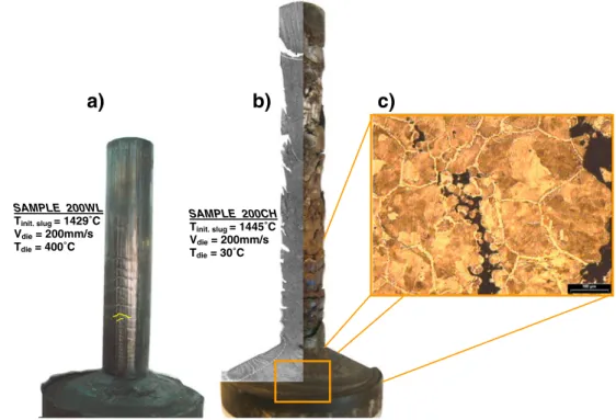
The flow within the parts is represented by different types of longitudinal macrographies. These show three distinct flows: B–E semi-solid, A–C quasi-static and D–F traditional forging, the dimensions of which depend primarily on the thixoforging speed and the tool tempera-ture. The size of the semi-solid zone grows with the increase of the forming speed and tool temperature, and this will determine the size of the two other zones. When the tool temperature and the forming speed are high enough, the flow of the semi-solid area is the same as that of a fluid, a very complex flow is then observed with characteristic lines illustrating conical gradients of displacement as opposed to the displacement of the material. Under special forming conditions, it is possible to see defects appearing on the surface of the parts (Fig.11a). These defects can be extreme and lead to a part that is made up of several pieces (Fig. 11 b). The micrographic analysis in the semi-solid samples centre (Fig. 11 c) exhibits the existence of an
intragranular defect thus excluding an origin related to the volumetric gradient from the liquid and solid phases of formed alloy. An investigation of the skin of the formed part (Fig. 12 a, b) confirms the existence of this intra-granular crack. Nevertheless, this one is not emerging. The crack is not emerging because the skin of the part has higher mechanical properties related to the temperature cooling due to heat exchange.
c)
a)
b)
SAMPLE 200WL Tinit. slug = 1429˚C Vdie = 200mm/s Tdie = 400˚C SAMPLE 200CH Tinit. slug = 1445˚C Vdie = 200mm/s Tdie = 30˚CFig. 11 Flow defects for thixoforging parts under extreme conditions SAMPLE 200WL Tinit. slug = 1429˚C Vdie = 200mm/s Tdie = 400˚C a) b) 200 µm
Fig. 12 Non-emerging intragranular cracks as flow defects during thixoforging
The micrographic study reveals that the grains of the semi-solid zone are larger. The grain size increases with the increase of the forming speed and tool temperature, corresponding to a reduction in heat exchange between the part and the die. Observations by SEM reveal the presence of bainite, which is an indication of a very fast cooling and thus high heat exchange. Decarburised zones can be observed at the exterior of the extruded part and in the entrance cone. Decarburising occurs during the induc-tion heating.
Increasing the thixoforging speed allows to obtain a more homogeneous hardness in the part. The increase in the tool temperature decreases the hardness slightly. Between two extreme thixoforging cases, the mechanical character-istics vary slowly, up to a maximum of 6%.
5 Conclusions
This paper presents steel thixoforging process and particu-larly explains process parameters of obtained part. This original work on C38 steel characterises macro–micro structures, mechanical properties, microhardness and ge-ometry of test parts. The main results of the study are as follows:
& Thermal exchange impacts strongly the material flow and the properties of the obtained parts.
& The thermal exchange is particularly influenced by the forming speed and the die temperature. Thus, these parameters are important control parameters of the thixoforging process.
& The slug temperature should be optimised in order to: allow the increase of the material desagglomeration and thus decreases the thixoforging load
avoid the collapse of the slug during heating and cooling during forming process leading to the ruin of the flow
& The thixoforging load decreases as the tool speed increases; shear strain leading to desagglomeration and the tool heat avoiding reagglomeration of the grains. Further experimental investigations are necessary for better determine action of condition for the nucleation of defects like cracks. The aim of this investigation is to determine the influence of the extrusion parameters on the nucleation of the cracks.
This work aims at the identification of the physical phenomena during steel thixoforging. This analysis also allows the reinforcement of the modelling of semi-solid materials. Thus it is important to quantify the thermal exchanges between the semi-solid part and the thixoform-ing tools as shown in our first results [24].
Moreover, this work associated with part research confirms the need to use closed die. Thixoforging process looks like net shape process. Experimental results lead to a need for (re)design of part starting from a functional specification [25, 26]. This approach of (re)design uses predictive tools such as constitutive laws developed and implemented in software such as Forge2008® [17,22].
These experimental works can be used to validate material modelisation and damage laws in semi-solid state. Industrial applications include not only global optimisation of thixoforging process (heating, transfers step die–press) but also“thixopart” (design, mechanical characteristics). Acknowledgements The authors thank Mr. Bastien and Mr. Morhain for their technological support and Mr. Pesci and Mrs. Favier for their scientific exchanges during this work. This work was also supported by the Ascometal Creas. Some tests were carried out on the experimental platform of Liege, under the responsibility of Mr. Rassili and with the technical support of Mr. Vaneetveld and Mr. Pierret.
References
1. Mori K, Saito S, Maki S (2008) Warm and hot punching of ultra high strength steel sheet. CIRP Annals—Manufacturing Technol-ogy 57(1):321–324
2. Kolleck R, Pfanner S, Warnke EP (2007) Development of cooled tools for press hardening of boron steel sheets. Key Eng Mater 344:225–232
3. Fukuda S, Eto H (2002) Development of fracture splitting connecting rod. JSAE Review 23(1):101–104
4. Doege E, Behrens B-A (1997) Reduce process chains due to the precision forging of gears-effect on the conventional forging technology. J Mater Process Technol 71(1):14–17
5. Berviller L, Bigot R, Martin P (2006) Technological information concerning integrated design of “net shape” forged parts. Int J Adv Manuf Technol 31(3–4):247–257
6. Takemasu T, Vazquez V, Painter B, Altan T (1996) Investigation of metal flow and preform optimization in flashless forging of a connecting rod. J Mater Process Technol 59:95–105 1–2 SPEC. ISS 7. Vazquez V, Altan T (2000) New concepts in die design—physical and computer modeling applications. J Mater Process Technol 98 (2):212–223
8. Chiarmetta G (1996) Thixoforming of automobile components. Proceeding of the 4th international conference on semi-solid processing of alloys and composites, Sheffield, 204–207 9. Chiarmetta G (2000) Thixoformage et gain de poids: application
industrielle du formage à l'état semi-solide. Hommes et Fonderie 302:29–34
10. Chiarmetta G, Zanardi L (1994) Production of structural compo-nents by thixoforming aluminium alloys. Proceeding of the 3rd international conference on semi-solid processing of alloys and composites, 235–244
11. Atkinson HV (2005) Modelling the semisolid processing of metallic alloys. Prog Mater Sci 50(3):341–412
12. Rouff C (2003) Contribution à la caractérisation et à la modélisation du comportement d'un acier à l'état semi-solide. Application au thixoforgeage. Thesis, ENSAM, Metz
13. Favier V, Rouff C, Bigot R, Berveiller M (2004) Micro-macro modelling of the isothermal steady-state behaviour of semi-solids. Int J Form Process 7:177–194
14. Favier V, Bigot R, Cezard P (2009) Transient and non-isothermal semi-solid behaviour: a 3-D micromechanical modeling. Mater Sci Eng A 1–2:8–16
15. Bigot R, Favier V, Rouff C (2005) Characterization of semi-solid material mechanical behavior by indentation test. J Mater Process Technol 160:43–53
16. Cezard P, Bigot R, Becker E, Mathieu S, Pierret JC, Rassili A. Thixoforming of steel: new tools conception to analyse thermal exchanges and strain rate effects. ESAFORM 2007, Zaragose, Spain pp. 2007, April 17–20
17. Cezard P (2006) Caractérisation, Modélisation et Simulation du comportement des alliages métalliques semi-solides. Application au thixoforgeage de l'acier. Thesis
18. Puttgen W, Bleck W, Seidl I, Kopp R, Bertrand C (2005) Thixoforged damper brackets made of the steel grades HS6-5-3 and 100Cr6. Adv Eng Mater 7(8):726–735
19. Puttgen W, Hallstedt B, Bleck W, Uggowitzer PJ (2007) On the microstructure formation in chromium steels rapidly cooled from the semi-solid state. Acta Mater 55(3):1033–1042
20. Puttgen W, Pant M, Bleck W, Seidl I, Rabitsch R, Testani C (2006) Selection of suitable tool materials and development of
tool concepts for the thixoforging of steels. Steel Research International 77(5):342–348
21. Robelet M (2004) Machine construction steel, process for hot forming a piece of this steel and piece obtained by this process. In European patent application, vol. EP1426460: ASCOMETAL 22. Cezard P, Favier V, Bigot R, Balan T, Berveiller M (2005)
Simulation of semi-solid thixoforging using a micro–macro constitutive equation. Comput Mater Sci 32(3–4):323–328 23. Favier V (2008) Micromechanics and homogeneisation techniques
for disordered materials: application to semi-solid materials. In: Atkinson HV (ed) Modelling of Semi Solid Processing, Chapter 6. Verlag, pp. 123–152
24. Becker E, Cezard P, Bigot R, Langlois L, Favier V, Pierret JC (2008) Steel thixoforging: heat exchange impact on the mechan-ical and metallurgmechan-ical features of thixoforged samples. Solid State Phenom 141–143:701–706
25. Puttgen W, Bleck W, Hirt G, Shimahara H (2007) Thixoforming of steels—a status report. Adv Eng Mater 9(4):231–245 26. Cezard P, Sourmail T (2008) Thixoforming of steel: a state of the
art from an industrial point of view. Solid State Phenom 141– 143:25–36
![Figure 3 illustrates the decreasing of steels melting point according to the increase in the carbon percentage and also in the associated elements of addition [17–20]](https://thumb-eu.123doks.com/thumbv2/123doknet/7305501.209499/5.892.264.822.1008.1067/illustrates-decreasing-according-increase-percentage-associated-elements-addition.webp)