UNIVERSITÉ DE SHERBROOKE Faculté de génie
Département de génie chimique et de génie biotechnologique
Liquéfaction de différentes sources de biomasse et de
lignine en présence de 2-MeTHF et de Nickel de Raney
Mémoire de maîtrise Spécialité : génie chimique
François LEMOINE
Jury : Jean-Michel Lavoie (directeur)
Ludovic Pinard (évaluateur externe) Esteban Chornet (évaluateur)
Michèle Heitz (rapporteur)
RÉSUMÉ
Au cours de ce projet, il a été démontré qu’il était possible d’appliquer un procédé utilisant comme solvant du 2-MeTHF ainsi que du Nickel de Raney comme catalyseur afin de valoriser par hydroliquéfaction différentes formes de biomasse résiduelles. Dans un premier temps, ce procédé, résumé dans un premier article, s’est avéré efficace pour trois différentes sources de carbone : des déchets ménagers, des boues de station d’épuration et des microalgues. Malgré que la réaction soit affectée par le type de solvant ainsi que la température d’opération, il a été démontré que le 2-MeTHF (un solvant vert) pouvait remplacer la tétraline (un solvant de source fossile) pour l’hydroliquéfaction de ces différentes sources de carbone. L’hydroliquéfaction de ces biomasses a permis la production d’huiles à haute valeur énergétique, se comparant à celle d’un biocarburant. Dans un deuxième article, le même procédé (utilisant le même solvant et catalyseur) a été optimisé pour la liquéfaction d’une fraction de la biomasse lignocellulosique soit la fraction oligomérique issue de la dépolymérisation alcaline de la lignine. Une analyse complète de la liquéfaction d’oligomères d’induline, lignine provenant des liqueurs issus de l’industrie papetière, a révélé la production de trois fractions : une fraction gazeuse, une liquide (soluble dans l’hexane) et une solide (insoluble dans l’hexane). L’analyse élémentaire de la fraction solide a révélé une baisse massique de 15,4% d’oxygène et une augmentation massique de 1,4% d’hydrogène par rapport aux oligomères utilisés comme réactifs. Une chaleur massique (HHV) de 34,0 kJ/g a été mesurée par bombe calorimétrique pour la fraction solide. L’analyse par chromatographie en phase gazeuse couplée à un spectromètre de masse (GC-MS) de la fraction liquide a permis d’identifier la présence de nombreux monomères tel le 2-methoxy-phénol, de 4-éthylgaïacol et le crésol. Une HHV de 34,2 kJ/g a été mesurée par bombe calorimétrique de la fraction liquide. La fraction gazeuse était principalement constituée de méthane et de CO2.
REMERCIEMENTS
En premier lieu, je voudrais remercier l’Institut de Chimie des Milieux et des Matériaux de Poitiers (IC2MP), la Chaire de Recherche Industrielle sur l’Éthanol Cellulosique (CRIEC) ainsi que CRB innovation pour avoir supporté cette étude.
Une mention toute spéciale à l’intention du Professeur Jean-Michel Lavoie de l’université de Sherbrooke pour m’avoir supervisé à travers un sujet récent et complexe comme la lignine. Il faut aussi mentionner Nicolas Béland et Luc Gilbert qui ont toujours pris le temps de me montrer comment exécuter efficacement les travaux manuels, sans qui les pertes en temps et en matériel auraient pu être substantielles.
Merci à ma famille pour m’avoir encouragé à essayer de nombreux domaines tout au long de mon parcours à travers le système d’éducation, qu’il soit au Québec, aux États-Unis ou encore en France. Je les remercie également pour leur support moral et financier tout au long de mes études.
Merci à :
Pour la vision industrielle amenée au projet et pour le soutien financier.
Et finalement merci à :
TABLE DES MATIÈRES
RÉSUMÉ ... iii
REMERCIEMENTS ... iv
LISTE DES TABLEAUX ... ix
CHAPITRE 1 LITTÉRATURE ... 11
1.1 Introduction ... 11
1.2 État de l’art de la valorisation de la biomasse ... 12
1.2.1 Biocarburant de 2e génération ... 12
1.2.2 Propriétés d’un biocarburant ... 15
1.2.3 Interactions entre le solvant et le catalyseur ... 16
1.2.3 Premier objectif et problématique ... 19
CHAPITRE 2 ALTERNATIVE FUEL PRODUCTION BY CATALYTIC HYDROLIQUEFACTION OF SOLID MUNICIPAL WASTES, PRIMARY SLUDGES AND MICROALGAE ... 21
2.1 Avant-propos ... 21
2.2 Résumé ... 22
2.3 Abstract ... 22
2.4 Introduction ... 23
2.5 Materials and Methods ... 25
2.5.1 Carbonaceous materials ... 25
2.5.2 Apparatus and characterization techniques ... 25
Proximate analysis ... 25
Chemical composition ... 26
Ultimate analysis ... 26
Higher Heating Value calculation and measurement ... 26
Hydroliquefaction reaction ... 27
Products analysis ... 28
2.6.1. Characterization of the carbonaceous materials ... 29
2.6.2 Hydroliquefaction reaction ... 36
Hydroliquefaction in the presence of tetralin ... 38
Hydroliquefaction in the presence of 2-methyl-hydro-furan ... 40
2.7 Conclusion ... 41
2.8 Acknowledgements ... 41
CHAPITRE 3 LA LIGNINE ... 43
3.1 LA CRIEC et la lignine ... 43
3.2 Potentiel énergétique de la lignine ... 44
3.3 Objectifs de la liquéfaction de la lignine ... 44
3.4 La lignine et ses défis ... 46
3.4.1 La lignine, le polymère ... 46
3.4.2 Les approches de valorisation de la lignine ... 49
3.4.4 Les composés modèles ... 51
3.4.5 Les oligomères (lignine dépolymérisée) ... 52
3.5 Second objectif et problématique ... 55
CHAPITRE 4 LIQUEFACTION OF ALKALINE PROCESSED LIGNIN USING RANEY NICKEL CATALYST AND 2-METHF AS SOLVENT ... 57
4.1 Avant-propos ... 57
4.2 Résumé ... 58
4.3 Abstract ... 58
4.4 Introduction ... 59
4.5 Materials and methods ... 62
4.5.1. Materials ... 62
4.5.2. Depolymerization ... 62
4.5.3 Precipitation & purification ... 62
4.5.4 Liquefaction of the oligomeric fraction... 64
4.5.5 Separation and recovery of the fractions ... 65
4.5.6 Characterization... 66
4.6 Results and discussion ... 67
4.6.1 Optimization of the liquefaction of hemp oligomers ... 67
4.6.2 Mass balance and chemical composition of the fractions produced from indulin lignin depolymerization ... 70
4.6.3 Composition of the solid fraction ... 72
4.6.4 Composition of the gas fraction ... 73
4.6.5 Durability of Raney Nickel catalyst ... 74
4.6.6 LF analysis and solvent degradation ... 75
4.7 Conclusion ... 78
4.8 Acknowledgment ... 78
CHAPITRE 5 CONCLUSION ... 79
ANNEXE A – DONNÉES ... 81
LISTE DES FIGURES
Figure 1 Diagramme élémentaire du cycle du carbone ... 13 Figure 2 Procédés de production de biocarburants ... 14 Figure 3 Schématisation simplifiée de la réaction entre un solvant donneur d’hydrogène (tétraline) au contact de radicaux libres ... 17 Figure 4 Schéma de l’hydroliquéfaction de la biomasse en utilisant le Ni Raney comme
catalyseur et la tétraline comme solvant (Beauchet et al., 2011) ... 18 Figure 5 Hydrogen transfer for tetralin (Scheme 1) and 2-MeTHF (Scheme 2) ... 24 Figure 6 Weight loss (solid line) and weight loss rate (dotted line) obtained by TGA coupled with mass spectrometry for primary sludge (a) and municipal solid wastes (b) materials ... 32 Figure 7 CO2 formation in function of temperature obtained by TGA coupled with mass
spectrometry for primary sludge (a) and municipal solid wastes (b) materials ... 33 Figure 8 NO emissions in function of temperature obtained by TGA coupled with mass
spectrometry for primary sludge (PS) and municipal solid wastes (MW) materials... 34 Figure 9 Weight loss (solid line) and weight loss rate (dotted line) (a), and CO2, NO formation
in function of temperature (b) obtained by TGA coupled with mass spectrometry for
microalgae ... 35 Figure 10 Solubilisation d’un phénol dans une solution basique aqueuse ... 45 Figure 11 Schéma de la matrice d'une paroi cellulaire de plante (Doherty et al., 2011) ... 46 Figure 12 Structure moléculaire hypothétique et partielle de la lignine (Dorrestijn et al., 2000) ... 47 Figure 13 Schéma du traitement de la lignine d'une bio raffinerie (Fechete et al., 2012) ... 48 Figure 14 Principales liaisons de la structure de la lignine (Dorrestijn et al., 2000) ... 51 Figure 15 Composés modèles imitant les liaisons ß-O-4 (Doherty et al., 2011) et 5-5 (Fechete et al., 2012; Jongerius et al., 2011) ... 51 Figure 16 2-méthyl-1,4-benzènediol (gauche) et 2-methoxyphénol (droite) ... 53 Figure 17 BCD of lignin and separation of the oligomeric fraction from the monomeric as described by (Beauchet et al., 2012) and recuperation of the refractory part of lignin ... 63 Figure 18 Scheme of the procedures used for the isolation and quantification of the Solid (SF) and Liquid (LF) fractions generated from the liquefaction of indulin lignin ... 65 Figure 19 Effect of temperature (a), of the amount of catalyst (Raney Nickel) (b), of the amount of solvent (2-MeTHF) (c) and of the initial pressure of hydrogen (d) on the
liquefaction of 5g of hemp oligomers. ... 69 Figure 20 H2/oligomers versus H2/2-MeTHF ratios with regards for the liquefaction of 5g of
LISTE DES TABLEAUX
Table 1 Quantitative characterizations of the different carbonaceous materials ... 30 Table 2 Effects of temperature and solvent on the municipal solid wastes (MW)
hydroliquefaction ... 36 Table 3 Effects of temperature and solvent on the primary sludge (PS) hydroliquefaction ... 37 Table 4 Effects of temperature and solvent on the microalgae (MA) hydroliquefaction ... 38 Table 5 Mass balance of the liquefaction reaction comprising the Solid Fraction (SF), the Liquid Fraction (LF), the produced gases and the quantification of the produced gas and the respective molar elemental loss ... 71 Table 6 Comparative results of the TGA and Elemental analysis of lignin, oligomers and SF and TGA curves for three replicates of the solid fraction obtained post treatment with Raney Nickel as compared to the original oligomers. ... 72 Table 7 Quantification of the produced gas and quantification of the respective molar
elemental loss ... 74
Table 8 Products identified by GC-MS analysis and obtained by the liquefaction reaction of Indulin oligomers ... 76
Table 9 Chaleurs de combustion des réactifs et les produits par bombe calorimétrique ainsi que la chaleur de réaction de la liquéfaction des oligomères d'induline ... 81
11
CHAPITRE 1
LITTÉRATURE
1.1 Introduction
La liquéfaction directe de matériel à base de carbone en huiles de solvolyse pourrait être une possibilité intéressante pour la production de carburants liquide. Cette énergie alternative renouvelable pourrait s’adapter à une large gamme de substrats souvent retrouvés sous la forme de déchets. En principe, presque toutes les sortes de biomasse du monde retrouvées peuvent être utilisées pour la production de biocarburants (Swain et al., 2011). Plusieurs résidus d’agriculture et de foresterie pourraient être considérés comme des sources abondantes et renouvelables de matrices carbonées avec un potentiel pour la liquéfaction en biocarburants (Liu & Zhang, 2008; Yip et al., 2009). Les substrats peuvent même inclure les déchets domestiques ainsi que les déchets d’industries alimentaires (Amin, 2009).
Le but de la réaction de liquéfaction consiste à réduire la quantité d’oxygène contenu dans les matériaux à base de carbone afin d’augmenter leur valeur énergétique. Si suffisamment d’hydrogène est incorporé dans la biomasse alors que l’oxygène est retiré, des produits liquides (aussi appelé huile de solvolyse) seront formés (Beauchet et al., 2011). De plus, les huiles résiduelles obtenues par réaction de liquéfaction pourraient être intégrées dans les raffineries de pétrole puisque le procédé mène à la production d’un intermédiaire pompable (Stevens et al., 2012).
Ce document présente donc, en une première section, une revue de la littérature sur la revalorisation de la biomasse en apportant notamment des précisions sur la réaction de liquéfaction. Ensuite, les résultats du premier objectif de cette recherche sont présentés à la 2e section de ce document. Ce premier objectif visait à vérifier la souplesse du procédé d’hydroliquéfaction en l’appliquant à différentes sources carbonées (microalgues, déchets ménagers et boues de station d’épuration) et en utilisant différents solvants typiquement donneurs d’hydrogène (tétraline et 2-MeTHF) afin de produire des huiles de solvolyse à hautes valeurs énergétiques. Cette étude a été réalisé à l’Institut de Chimie des Milieux et des
Matériaux de Poitiers (IC2MP) en France sous la direction du Dr Ludovic Pinard. Les membres du comité d'encadrement qui ont été appelés à statuer sur ce premier objectif de ce travail sont, outre le directeur de recherche, la Dr Irène Maupin et le Pr Yanick Pouilloux. Les résultats de cette étude ont été publiés dans le journal Bioresource Technology et sont présentés à la section 2 de ce document.
Le second objectif de cette étude consistait à appliquer la réaction d’hydroliquéfaction à la lignine, une biomasse beaucoup plus récalcitrante aux réactions chimiques que celles abordées à la section 2. C’est pourquoi une section complète (3e section) sera accordée à cette molécule complexe afin de mieux cerner le potentiel énergétique de la lignine ainsi que les obstacles à sa valorisation.
Finalement, les résultats du second objectif de cette recherche sont présentés à la 4e section de ce document. Ce deuxième objectif, enrichi par l’apprentissage fait dans le domaine des catalyseurs chez le partenaire français, a été réalisée au Québec dans les infrastructures de la Chaire de Recherche Industrielle en Éthanol Cellulosique (CRIEC). Cet objectif consistait à valoriser la lignine par l’application du procédé de liquéfaction visant la production de molécules à valeur ajoutée. Les résultats de cette étude sont présentement en soumission au Journal Bioresource Technology et sont présentés à la section 4 de ce document. Une conclusion suivant la 4e section de ce document vient par la suite clôturer l’ensemble des travaux effectués dans le cadre de cette étude.
1.2 État de l’art de la valorisation de la biomasse
1.2.1 Biocarburant de 2
egénération
L’énergie contenue dans les différentes sources carbonées (comme le bois, les déchets issus de l’utilisation du bois, les résidus forestiers et d’agriculture, les déchets ménagers, les boues de station d’épuration, etc…) représente un important potentiel énergétique. Par ailleurs, ces
sources énergétiques peuvent être considérées comme renouvelables par opposition aux
énergies d’origine fossile. Les avantages majeurs de l’utilisation de la biomasse comme source énergétique sont :
La biomasse est renouvelable et disponible
L’utilisation de la biomasse comme source énergétique ne contribue pas à
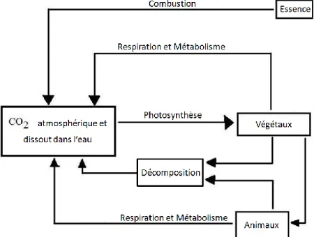
l’augmentation nette de la concentration atmosphérique en CO2. L’énergie fossile est
une source de carbone excentrée du cycle de carbone et sa combustion entraine ponctuellement une augmentation des taux de CO2 dans l’atmosphère (figure 1).
Figure 1 Diagramme élémentaire du cycle du carbone
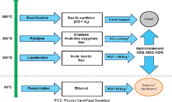
L’utilisation de ressources renouvelables pour la production de biocarburants peut être faite par l’intermédiaire de deux approches technologiques : par conversion biochimique (fermentation) ou par conversion thermochimique (liquéfaction, pyrolyse ou gazéification) (voir la figure 2).
Figure 2 Procédés de production de biocarburants
La gazéification est un procédé à haute température (800°C) visant à transformer la biomasse en un gaz de synthèse dont les composés actifs en synthèse sont le monoxyde de carbone et hydrogène. Ce gaz de synthèse, agissant comme bloc de base aux conversions chimiques plus élaborées, peut ensuite être utilisé pour la formation d’hydrocarbures par le procédé Fisher-Tropsch ou encore pour la production d’éthanol. La pyrolyse est un procédé à température moyenne (450°C) où la biomasse est chauffée a différente vitesse selon le type de pyrolyse (rapide ou lente) en l’absence d’oxygène menant à la production de gaz de synthèse, de bio-huile et de biochar (Brigwater et al., 1999). La production de liquides nécessite de très courts temps de résidence (1s) afin de minimiser les réactions secondaires (Brigwater et al., 1999). Après refroidissement et condensation, un liquide noir est formé. Ce dernier (voir Figure 2) possède une chaleur massique représentant environ la moitié d’un carburant conventionnel. La liquéfaction directe de la biomasse, contrairement au deux derniers procédés, réfère toujours à la conversion du matériel lignocellulosique (finement divisée) mais cette fois sous l’action d’un gaz réducteur (H2) et en présence d’un solvant. Lors du traitement, la structure
des polymères présents dans le matériel d’origine subit une série complexe de réactions chimiques déclenchées par l’augmentation de la température. Le résultat immédiat est la fragmentation du polymère initial en une multitude d’espèces moléculaires de différentes
tailles qui sont, pour la plupart, stabilisées par l’addition d’hydrogène. La liquéfaction (ou solvolyse) comporte deux avantages majeurs :
L’utilisation de solvant dilue la concentration des produits de réaction empêchant les réactions croisées et les réactions inverses
Les températures de réaction nécessaires sont faibles comparativement aux températures de réaction de la pyrolyses et de la gazéification.
1.2.2 Propriétés d’un biocarburant
Le procédé idéal de liquéfaction éliminerait totalement l’oxygène dans la biomasse tout en conservant suffisamment d’hydrogène pour former des liquides (biohuiles). Les caractéristiques requises pour être considéré comme une biohuile sont :
-Teneur en oxygène inférieure à 6 % massique -Chaleur massique supérieure à 40kJ.kg-1
-Ratio molaire H/C supérieur à 1,5 (Wang et al., 2008).
Trois approches peuvent théoriquement être employées afin de réduire le taux d’oxygène de la biomasse impliquant une décarbonylation (perte de CO), une décarboxylation (perte de CO2)
ou encore une déshydratation (perte de H2O). L’élimination de l’oxygène par la formation de
CO n’est pas souhaitable puisqu’une telle réaction mène à une faible production de biohuile ce qui implique également la perte d’un atome de carbone par atome d’oxygène. La formation de CO2 représente une meilleure option, mais la meilleure façon de désoxygéner la biomasse
tout en conservant une haute production en biohuile reste l’élimination de l’oxygène par la formation d’H2O. L’élimination d’eau implique une réduction de la teneur en hydrogène de la
biomasse qui pourrait résulter en la production de « coke » advenant sa désoxygénation totale par l’entremise de cette formation. Afin d’obtenir des produits liquides avec un ratio H/C se rapprochant de la définition d’une biohuile (ratio H/C d’environ 1,6 – 2), il est primordial que la réaction de liquéfaction soit effectuée sous une atmosphère pressurisée d’hydrogène et/ou
avec un solvant donneur d’hydrogène. Un tel environnement de liquéfaction permet de désoxygéner la biomasse tout en hydrogénant les produits de réaction évitant par le fait même la production de « coke ». Malheureusement, les biocarburants issus de la réaction de liquéfaction ne sont pas utilisables dans les moteurs à combustion destinés au transport sans qu’ils subissent des traitements de purifications afin pour atteindre les standards exigés. La composition chimique des biohuiles doit être ajustée via des réactions d’hydroisomérisation et/ou par craquage et/ou par l’addition d’hydrogène.
1.2.3 Interactions entre le solvant et le catalyseur
Les catalyseurs bifonctionnels à base de métaux de transition, spécialement les catalyseurs à base de nickel-molybdène et cobalt-molybdène ont souvent été mentionnés dans la littérature. Ces catalyseurs sont reconnus comme étant effectifs pour l’hydrodesoxygénation de biohuiles provenant du traitement de différent types de biomasse et pour la liquéfaction de différentes sources de biomasse, notamment de bois (Boocock et al., 1979, 1980, 1982; Klopries et al., 1990).
Moins dispendieux que les catalyseurs bifonctionnels, l’utilisation des catalyseurs à base de fer a aussi été rapportée pour l’hydrodesoxygénation de pin gris sous forme de poudre par Xu et Etcheverry (2008). Ces derniers ont observé que l’addition de FeS ou de FeSO4 favorise à la fois la conversion de la biomasse et la production
d’huile. Une conversion maximale en huile de 63% a été obtenu lor s d’une réaction dans l’éthanol utilisant 5% de FeSO4, 5 MPa d’hydrogène, sous une température de
350°C durant 40 minutes. Bestue-Labazuy et al. (2009) ont utilisé différent additifs à base de fer pour la liquéfaction de bois de peuplier dans l’eau à 340°C . La production d’huile a également été favorisée par la présence de Nickel de Ran ey (Boocock et al., 1982) ou de palladium (Meier et al., 1986).
Les plages de température optimales pour la liquéfaction directe de la biomasse varient généralement entre 250°C et 450°C. Les températures sous 250°C inhibent les
cinétiques de réaction alors qu’au dessus de 450°C, des réactions secondaires telles gazéification deviennent plus significative que la solvolyse et l’hydrogénolyse.
Lors de la liquéfaction de la biomasse, des réactions ioniques et radicalaires peuvent se produire (Antal et al., 1991; Kabyemela et al., 1997) qui, pour la plupart, sont reliées à la polarité du système réactionnel. Ainsi le solvant revêt une importance capitale pour ce type de réactions. Par exemple, la littérature mentionne de meilleurs conversions lorsque des solvants polaires comme l’acétone et l’éthanol (Liu & Zhang, 2008), le propanol et le butanol (Ogi & Yokoyoma, 1993), le glycérol (Demirbas, 2008), l’eau (Boocock et al., 1982; Eager et al., 1982; Liu & Zhang, 2008) ou des liquides ioniques (Miyafuji et al., 2009) sont employés. Le solvant contribue à la diminution de la densité de l’huile produite en prévenant les réactions croisées et les réactions inverses par la dilution des produits de réaction. En absence de solvant, les réactions croisées augmenteraient la grosseur des molécules produites et augmenterait également la densité des produits. Les radicaux peuvent être stabilisés par la présence d’un solvant donneur d’hydrogène et la tétraline est un exemple très commun et rapporté fréquemment comme solvant pour ce type de réaction au sein de la littérature (Lemoine et al., 2012) (Figure 2).
Figure 3 Schématisation simplifiée de la réaction entre un solvant donneur d’hydrogène (tétraline) au contact de radicaux libres
En guise d’alternative plus « verte » à l’utilisation de la tetraline, le 2-Me-THF pourrait être employé. Ce dernier peut être produit par la réduction du furfural qui a son tour peut être généré par déshydratation des sucres à 5 carbones composant les hémicelluloses. Le mécanisme de transfert de l’hydrogène moléculaire aux produits de liquéfaction via la tétraline, a été décrit en détail par Curran et al. (1967).
La réaction d’hydroliquéfaction peut donc être divisée en deux étapes (figure 4), une étape catalytique et une étape non-catalytique. La première étape (figure 4, step 1), l’étape non catalytique, consiste en une solvolyse par dégradation thermique menant à la décarboxylation de la biomasse (formation de CO2). La deuxième étape (figure 4, step 2) requiert l’action du
catalyseur qui permet la fixation et la formation d’hydrogène radicalaire. Cet hydrogène servira ensuite à la stabilisation des fragments de la biomasse issus de la première étape. Dans le cas où le solvant utilisé est un solvant donneur d’hydrogène comme la tétraline (Curran et al., 1967), celle-ci peut également contribuer au transfert d’hydrogène en relâchant des hydrogènes sous forme radicalaire, processus stabilisé par l’aromaticité du naphtalène en découlant. Ces radicaux joueront le même rôle que ceux fixés à la surface du catalyseur, c'est-à-dire de stabiliser les fragments de la biomasse issus de la première étape. Le naphtalène alors produit est rapidement réhydrogéné à la surface du catalyseur reformant la tétraline. La tétraline agit donc comme donneur d’hydrogène en assurant le transport de l’hydrogène du catalyseur vers les réactifs. La tétraline, en augmentant la portée du catalyseur, prévient alors plus efficacement les réactions entre les molécules issus de la première étape et par le fait même leur condensation sous forme de « coke ». L’huile produite est désoxygénée par l’entremise de la formation d’H2O. La formation de CH4 est aussi observée par hydrogénolyse
et méthanation du CO2 (Beauchet et al., 2011).
Figure 4 Schéma de l’hydroliquéfaction de la biomasse en utilisant le Ni Raney comme catalyseur et la tétraline comme solvant (Beauchet et al., 2011)
H2 catalyst catalyst catalyst catalyst solvolysis oil Green Wastes CO2 CH4 CH4 solvolysis oil non oxygenated D D D D Step 1 Step 2 H2 catalyst catalyst catalyst catalyst solvolysis oil Biomass/waste CO2 CH4 CH4 solvolysis oil non oxygenated D D D D Step 1 Step 2
1.2.3 Premier objectif et problématique
Des travaux antérieurs rapportent l’hydroliquéfaction catalytique directe d’une biomasse composée d’un mélange de déchets verts (paille, bois et herbe) le tout en utilisant le Nickel de Raney comme catalyseur et de la tétraline comme solvant. Il a été démontré que le catalyseur augmentait la qualité des huiles produites en augmentant le transfert d’hydrogène entre le solvant et l’huile de solvolyse. Dans le même ordre d’esprit, Lemée et al. (2012) ont démontré qu’un prétraitement biologique (maturation), promouvait la conversion de la biomasse en huile de solvolyse de qualité supérieure. Plus la biomasse était préalablement déstructurée par des dégradation biologiques naturelles, meilleur s’en retrouvait la conversion et la qualité des biohuiles produites. C’est pourquoi la transformation de biomasses fortement modifiées comme les déchets ménagers et les boues de station d’épuration en biocarburant par hydroliquéfaction représentent en plus d’un défi de taille, une opportunité.
Ce premier objectif de ce projet vise à appliquer le procédé d’hydroliquéfaction utilisant du Nickel de Raney comme catalyseur sur trois différentes biomasses : deux biomasses fortement modifiées (déchets ménagers et boues de station d’épuration) et une biomasse brute (microalgues). La biomasse est une source de carbone renouvelable, mais elle possède une composition chimique complexe et très variable selon la source. Cette variabilité aura nécessairement un impact sur la nature des produits obtenus suite à l’application du même procédé sur des sources de carbone variables. Une bioraffinerie devra se baser sur une économie d’échelle pour être rentable et en ce sens il s’avère inévitable de devoir varier la source de carbone intrant. C’est la raison pour laquelle une étude de la versatilité d’un procédé sur la revalorisant d’une large gamme de biomasses est d’intérêt majeur pour une éventuelle application industrielle. Les critères de performance du procédé seront basés sur les rendements en huiles, la production de gaz ainsi que la production de résidu solide. Une attention particulière sera portée sur la qualité de l’huile en terme de valeur énergétique et de composition chimique. Il est important que les huiles produites atteignent un certain potentiel énergétique afin de s’assurer de leur éventuel utilisation dans les moteurs à combustion.
Le deuxième point important de ce projet vise le choix du solvant. Un procédé visant la production d’un biocarburant gagnera à utiliser un solvant « vert » tel le 2-MeTHF au lieu d’un solvant provenant d’une source fossile non renouvelable comme la tétraline.
CHAPITRE 2
ALTERNATIVE FUEL
PRODUCTION BY CATALYTIC
HYDROLIQUEFACTION OF SOLID MUNICIPAL
WASTES, PRIMARY SLUDGES AND
MICROALGAE
2.1 Avant-propos
Auteurs et affiliation :
F. Lemoine, Étudiant à la maîtrise, Université de Sherbrooke, Faculté de Génie, Département de génie chimique
I. Maupin, Étudiante au doctorat, Institut de Chimie des Milieux et Matériaux de Poitiers (IC2MP)
L. Lemée, Professeur, Institut de Chimie des Milieux et Matériaux de Poitiers (IC2MP) J.-M. Lavoie (Professeur), Professeur Agrégé, Université de Sherbrooke, Faculté de Génie, Département de génie chimique
J.-L. Lemberton, Professeur, Institut de Chimie des Milieux et Matériaux de Poitiers (IC2MP) Y. Pouilloux,Professeur, Institut de Chimie des Milieux et Matériaux de Poitiers (IC2MP)
L. Pinard, Maître de Conférences, Institut de Chimie des Milieux et Matériaux de Poitiers (IC2MP)
Date d’acceptation : Accepté le 30 avril 2013 Revue : Journal Bioresource Technology
Référence : Lemoine F., Maupin I., Lemée L., Lavoie J.-M., Lemberton J.-L., Pouilloux Y.,
Pinard L. (2013). Alternative fuel production by catalytic hydroliquefaction of solid municipal wastes, primary sludges and microalgae. Bioresource Technology, 142, 1-8
Titre Français : Production alternative de carburant par hydroliquéfaction catalytique de
déchets municipaux, de boues de station d’épuration et de microalgues.
Contribution au document : Cet article contribue au mémoire en présentant les résultats des
différentes conversions et analyses des biohuiles obtenues dans le cadre de ce projet par l’hydroliquéfaction catalytique directe de déchets municipaux, de boues de station d’épuration et de microalgues.
2.2 Résumé
Cette recherche rapporte l’hydroliquéfaction catalytique de trois différentes sources de carbone (déchets municipaux (DM), boues de station d’épuration (B) et microalgues (M)). La réaction d’hydroliquéfaction a été effectuée sous une pression d’hydrogène à différentes températures (330, 380 et 450 °C) avec un catalyseur de Nickel de Raney. De plus, deux solvants donneurs d’hydrogène ont été utilisés comme milieu réactionnel soit un solvant d’origine fossile (la tétraline) et un solvant d’origine renouvelable (le 2-méthyltétrahydrofurane). Les analyses (ATD-ATG, ICP-AES, quantification des lipides) des différents déchets ont relevé des caractéristiques et propriétés physico-chimiques similaires pour les DM et les B, mais différentes pour les M. L’hydroliquéfaction de ces différentes sources de carbone a permis d’obtenir d’importantes conversions en huiles possédant dans l’ensemble des valeurs énergétiques similaires à celles d’un biocarburant. Le 2-méthyltétrahydrofurane s’est révélé plus efficace que la tétraline pour le traitement des biomasses qui ont déjà subit une forte biodégradation (DM et des B) alors que de meilleurs résultats ont été obtenus avec la tétraline pour la biomasse brute comme les M.
2.3 Abstract
An alternative fuel production was investigated through catalytic hydroliquefaction of three different carbonaceous sources: solid municipal wastes (MW), primary sludges (PS), and microalgae (MA). The reaction was carried out under hydrogen pressure, at different temperatures (330, 380 and 450 °C), with a Raney nickel catalyst and two different hydrogen donor solvents: a ‘‘fossil solvent’’ (tetralin) and a ‘‘green solvent’’ (2-methyl-hydro-furan). The feeds analyses (TDA–TGA, ICP-AES, lipids quantification) showed that MW and PS had similar characteristics and physico-chemical properties, but different from those of MA. The hydroliquefaction of these feeds allowed to obtain high oil yields, with a significant energetic value, similar to that of a biopetroleum. 2-methyl-hydro-furan was more efficient than tetralin for the treatment of the strongly bio-degraded biomasses MW and PS, while better results were obtained with tetralin in the case of MA.
Keywords: Hydrogen donor solvent, Liquefaction, Solid municipal wastes, Primary sludges,
2.4
Introduction
Various carbonaceous materials, such as algae, sludge and household, agricultural and forestry wastes, can be used as substitutes to fossil fuels. Furthermore, the wastes valorisation allows to avoid irreversible environmental damages such as the contamination of underground water reservoirs and of fertile lands, the pollution of oceans and the emission of hazardous gases in the air. These carbonaceous materials can be converted into energetic and recoverable oils by biological conversion (Amin, 2009; Sun and Cheng, 2002) or by thermochemical processes, such as gasification (Amin, 2009; Swain et al., 2011), pyrolysis (Amin, 2009; Meier and Faix, 1999; Swain et al., 2011) or liquefaction (Amin, 2009; Swain et al., 2011). However, these oils have to be upgraded before their use as fuels.
Among the thermochemical processes, direct liquefaction is a suitable method allowing to work at low temperature (250-350°C) and to avoid energy-guzzling pretreatments, such as drying. It was already applied to a wide range of materials: algae (Amin, 2009; Yang et al., 2011), coal (Li et al., 2008a), sludge (Inoue et al., 1997, Itoh et al., 1994; Li et al., 2010), mixed wastes (Hwang et al., 2012; Sugano et al., 2009), agricultural residues (Guo et al., 2008; Li et al., 2008b; Wang et al., 2008), floral biomass (Lu et al., 2009), woody biomass (Wu et al., 2008, 2009) or green wastes (Beauchet et al., 2011; Lemée et al., 2012). Whatever the starting material, the hydroliquefaction process allowed to obtain high oil yields, ranging between 35 and 72 wt.%. Moreover, it removes more than 80 wt.% of the oxygen present in the starting materials (Beauchet et al., 2011; Guo et al., 2008; Lemée et al., 2012; Li et al., 2008b; Lu et al., 2009; Wang et al., 2008; Wu et al., 2008, 2009). Consequently, the bio-oil obtained had a Higher Heating Value (HHV) similar to that of a bio-petroleum (~ 40 kJ.g-1). Lastly, this process is economically positive since, as shown by Itoh et al. (1994), the sludge deoxy-liquefaction can be performed without any auxiliary fuel and can produce 1.5 tons of heavy oil as surplus energy, thus confirming the liquefaction process suitability.
However, this process can be improved by using a hydrogen donor solvent and a catalyst. In a previous work (Beauchet et al., 2011), direct catalytic hydroliquefaction of a biomass composed of a mixture of green wastes (straw, wood and grass) using a Raney nickel catalyst
and tetralin (Scheme 1) as a solvent was studied. It was shown that the catalyst enhanced the oil quality by increasing the hydrogen transfer between the solvent and the solvolysis oil. As a consequence, the oxygen content decreased whilst at the same time enough hydrogen was incorporated to form liquid products (alternative petroleum). Although very efficient as a hydrogen donor, tetralin remains a very expensive1 (4000-4200 USD.tonne-1). Consequently, for economic and environmental reasons, it would be of interest to replace it by a biomass-derived solvent such as 2-methyl-hydro-furan (MeTHF, Scheme 2). Indeed, it has the advantages to be produced from renewable resources, to exhibit highly efficient extraction properties and also to have a stable price since it can be produced out of C5 carbohydrates via the furfural route and that its actual market value is around 2000 USD.tonne-1 (estimated from the price of furan2).
Figure 5 Hydrogen transfer for tetralin (Scheme 1) and 2-MeTHF (Scheme 2)
The aim of this work was to check the versatility of the hydroliquefaction process by using three different biomasses: two strongly modified biomasses (primary sludge and municipal solid wastes), and a crude biomass (microalgae). The performances of the liquefaction process were estimated from the oil yields, the gas production and the amount of solid residue. A particular attention was turned to the oil quality in terms of energy value and elemental composition. A second aspect to be considered in this work was the influence of the nature of the solvent, tetralin or MeTHF.
1 OCI Company Ltd., South Korea
2 Qingdao Jinwei Import And Export Co., Ltd., China
O O
2 H
2+
2 H
2+
Scheme 1 Scheme 22.5
Materials and Methods
2.5.1
Carbonaceous materials
The carbonaceous materials used in this work were:
- Solid municipal wastes (MW) provided by Veolia Environnement Recherche &
Innovation, Limay (France);
- Primary sludges (PS), treatment plant residue, provided by the Institut
Agronomique et Vétérinaire (IAV), Rabat (Morocco);
- Microalgae (MA), supplied by “Valagro carbone renouvelable”, Poitiers
(France).
The microalgae were produced using a nutritive solution containing 14.2 wt.% of NO3, 7.3
wt.% of SO3, 26 wt.% of K2O and 7 wt.% of P2O5. All the materials (MW, PS and MA) were
crushed to obtain a particle size smaller than 0.4 mm, then freeze-dried (Bioblock Scientific Christ Alpha 1-4).
2.5.2
Apparatus and characterization techniques
Proximate analysis
Proximate analysis, carried out using thermo gravimetric (TGA) and thermo differential (TDA) analyses, allowed to quantify the moisture, organic matter (OM) and ash contents of the carbonaceous materials. TGA-TDA was carried out using a STD Q600 TA Instrument coupled with a QGA Hidden Analytical mass spectrometer. Samples were heated at 105°C under air (heating rate 5°C.min-1) then left at this temperature for 2 hours before being heated at 800°C (5°C.min-1) for microalgae and 900°C for municipal solid wastes and primary sludges.
Chemical composition
The lipids content was determined using an automatic ASE 100 extractor working with a dichloromethane/methanol mixture (2/1 v/v). Five extractions of three cycles each were done on each carbonaceous material. The recovered solvent was then evaporated and the mass of the residue was measured and considered as lipids (Calderoni and Schnitzer, 1984).
Ultimate analysis
The elemental composition (C/H/N/S) of the feedstocks and of the products were obtained using an elemental analyser (CE Instruments NA 2100 Protein) after total combustion at 1020°C under oxygen. The oxygen content was then estimated by difference.
The chemical composition of the ashes was determined using an Inductively Coupled Plasma (ICP). The solid samples underwent first an acidic digestion, then they were heated up to 6 000°C – 8 000°C in order to vaporize and ionize the metallic compounds to be quantified: Na, K, Mg, Ca, Fe, Zn, Al and Si. The ions were detected and analysed by atomic emission spectrometry.
The organic matter (OM) composition of MW and PS materials were characterized by combustion. The weight loss and the nature of the combustion products (CO2, NO) were
followed by thermo differential analysis (TDA)/thermo gravimetric analysis (TGA) coupled with mass spectrometry analysis. These techniques were useful to investigate OM composition that correlates with the actual tendency in the field (Dell’Abate et al., 2000; Gómez-Rico et al., 2005; Pietro and Paola, 2004; Smidt and Lechner, 2005).
Higher Heating Value calculation and measurement
The Higher Heating Value (HHV, kJ.g-1), which can be defined as the total energy content released when the material is burned under air, was obtained from the elemental analysis using the Dulong’s formula (Zhong and Wei, 2004, Lui et al. 1996):
%(S) 0.00095wt. 8) / (O) wt.% -(H) 1.422(wt.% + (C) wt.% 0.03383 = HHV Eq. 1
In order to correlate these results, HHV was also measured using a calorimetric bomb, which was calibrated with n-decane before testing. A selected mass of sample was placed in the calorimetric bomb under a 25 MPa oxygen pressure. The apparatus was put in 2 L of water (specific heat : 4,186 kJ.g-1.°C-1) before the ignition of the product by an iron string subjected to a small electric current. The water temperature variation was measured in real time with a thermocouple. The experiments were carried out until all the biomass was consumed, which was assumed to be when the temperature was stable during more than 30 seconds. The HHV was then obtained as follows:
Msample 1000
T T C M ) g . kJ ( HHV 1 H2O p,H2O 2 1 Eq. 2
Msample
T T 36 . 8 ) g . kJ ( HHV 1 2 1 Eq. 3where MH2O, CpH2O, T1, T2 and Msample are the mass of water (2000 g), the specific heat of
water, the initial temperature, the final temperature and the mass of the sample, respectively.
Hydroliquefaction reaction
The experiments were carried out in a 300 mL stainless steel autoclave. The reactor was filled either with 70 g of tetralin (Acros Organic, purity = 98%) or with 70 g of 2-methyl-hydro-furan (Sigma Aldrich, purity = 99%), 5 g of material (MW, PS or MA) and 1 g of Raney nickel slurry in water. This catalyst was supplied by Sigma Aldrich in an activated form. The autoclave was first purged several times with hydrogen in order to eliminate traces of air, after what the hydrogen pressure was adjusted to 16 bar. Pressure was recorded versus time-on-stream. The reactor was heated up to the chosen temperature at 10°C.min-1 without stirring. As soon as the working temperature was reached and stabilized, stirring began (1000 rpm) which was considered as zero reaction time. The working pressure ranged between 40 and 70 bar, depending on the reaction temperature. After a 15 minutes reaction time, stirring was stopped and the autoclave was rapidly cooled down to room temperature.
Products analysis
At the end of an experiment, the reactor contained gas, liquid and solid materials which were separated and analysed as described previously (Beauchet et al., 2011; Lemée et al., 2012). In order to check reproducibility, each experiment was carried out twice. Results showed that the yields measured were the same +/- 9 wt.%.
The solid residue, composed of spent catalyst, unconverted material and insoluble organic matter, was separated from the solvent by filtration. It was then washed with dichloromethane (CH2Cl2) which was combined with the solvent. The solid residues were dried at 90°C under
vacuum during 3 hours, the solvent and the bio-oil were separated by distillation.
The total feedstock conversion X was deduced from the mass of insoluble materials, following Equation 4:
×100 material) of matter organic of (mass catalyst) and ash without materials insoluble of (mass -1 = % X Eq. 4For experiments with tetralin as the solvent, the mass of hydrogen transferred from tetralin to the material (THT) was determined by analyzing the solvent by gas chromatography (Varian 3400, equipped with a 30 m DB5 type capillary column and a FID detector). THT was deduced from the concentration in naphthalene, which was directly linked to the conversion of tetralin. Under our experimental conditions, tetralin was only converted into naphthalene which showed that it acted as a reducing agent, and not as an oxidizing agent since only traces of decalin were observed. The mass of hydrogen (in milligrams) transferred from tetralin to the material was calculated as follows (on a 1000 mg basis):
((T.x)/M) 4000/132
=
THT Eq. 5
where T is the amount of tetralin (mg) in the starting mixture, M the amount of material sample (mg) and x the molar fraction of naphthalene produced.
X 516 =
THT Eq. 6
where X is the wt.% of naphthalene formed.
Theoretically, the same calculation would be possible in the case of MeTHF. However, no 2-methyl-furan (2MF) was detected in the recovered solvent. Due to a boiling point lower than the one of MeTHF (63°C against 80°C), 2MF was removed during the distillation step. Consequently, THT could not be estimated.
The oil yield was calculated as the mass of oil divided by the mass of bone-dry organic matter in the sample: 100 × material) of matter organic dry of (mass oil) of (mass = yield Oil Eq. 7
The difference between the conversion and the oil yield corresponded to the yield into gas and “light oil”. Since the amount of light oil was negligible in most cases, we assumed that this difference corresponded to the gas yield.
The elemental composition of oils was also obtained using a C/H/N/S analyzer, as explained for the ultimate analysis (Section 2.2.3).
2.6 Results and Discussion
2.6.1. Characterization of the carbonaceous materials
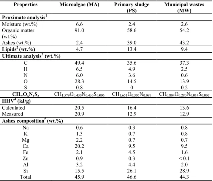
The quantitative characterizations of the three carbonaceous materials (PS, MW and MA) including moisture, organic matter, ashes and lipid contents, ultimate analysis (CHNS/O), HHV and ashes elemental composition are presented in Table 1.
The elemental composition (CHNS/O) of PS and MW was very similar with respect to the carbon and oxygen contents: ~ 35 wt.% and ~ 15 wt.%, respectively. On the other hand, differences were observed for the nitrogen and hydrogen contents, which were respectively 6 and 2 times higher for SL than for HW. Despite this difference, the HHV were the same for
the two samples (~ 13 kJ.g-1) and close to those calculated from the elemental analysis. This low HHV value is, in agreement with the literature (Li et al., 2010), mainly due to the low Organic Matter (OM) content (~ 55 wt.%).
Table 1Quantitative characterizations of the different carbonaceous materials Properties Microalgae (MA) Primary sludge
(PS) Municipal wastes (MW) Proximate analysis1 Moisture (wt.%) 6.6 2.4 2.6 Organic matter (wt.%) 91.0 58.6 54.2 Ashes (wt.%) 2.4 39.0 43.2 Lipids2 (wt.%) 4.7 13.4 9.4 Ultimate analysis3 (wt.%) C 49.4 35.6 37.3 H 6.5 4.9 2.5 N 6.0 3.6 0.6 O 28.3 14.5 13.9 S 0.8 0 0.2 CHwOxNySz CH1.579O0.430N0.430S0.006 CH1.651O0.305N0.087 CH0.804O0.280N0.014S0.002 HHV4 (kJ/g) Calculated 20.5 16.4 13.6 Measured 20.9 12.9 12.9 Ashes composition5 (wt.%) Na 0.6 0.3 0.8 K 1.3 0.7 0.8 Mg 2.2 0.7 0.7 Ca 20.2 9.5 9.5 Fe 2.1 4.5 1.6 Zn 0.9 0.3 < 0.1 Al 3.2 4.4 2.0 Si 15.5 26.1 28.9 Total 45.9 46.6 44.3
1: Determined by thermo gravimetric and thermo differential analysis 2: Obtained by extraction (dichloromethane/methanol 2/1 v/v)
3: Ultimate analysis were done after total combustion at 1020°C under oxygen 4: High Heating Value
5: Measured by ICP-AES
The high ashes amount in both materials was linked to the biomass decomposition, when part of the organic matter was converted into bio-gas. Indeed, ashes content would increase due to the reduction of the carbon content that was digested either to methane or CO2 during the
organic treatment previously undergone. The main metals in the PS and MW ashes were silica, calcium, aluminium and iron. Other metals, such as lead or cadmium could also be present (Jung et al., 2006; Li et al., 2010).
The OM contained 9.4 wt.% and 13.4 wt.% lipids in PS and MW, respectively. These values were similar to those found in literature (Inoue et al., 1996; Pokorna et al., 2009).
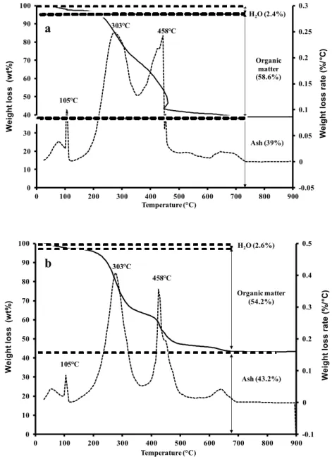
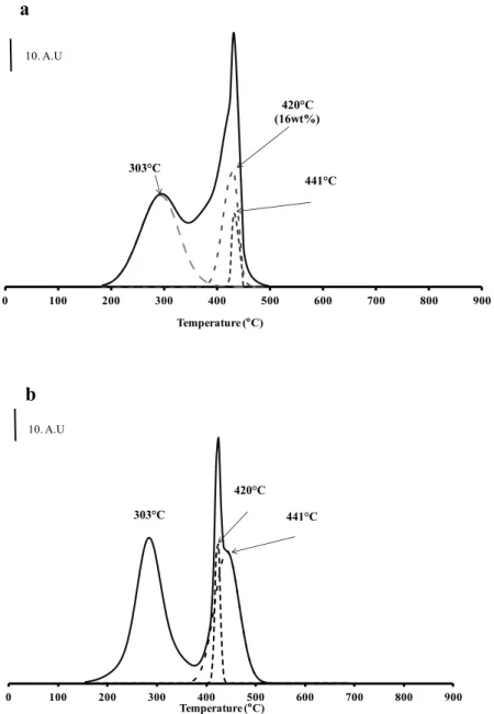
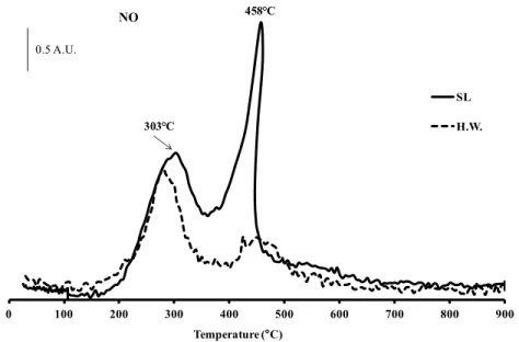
Figures 6, 7 and 8 show the weight losses and the amounts of the combustion products (CO2,
NO) measured during the combustion of OM. In general, the OM combustion is characterized by two exothermic peaks around 250-350°C and 400-550°C respectively. The first one corresponds to the volatilization of light compounds such as aliphatic molecules, probably fatty acids from biomass (Dell’Albate et al., 2000) or carbohydrates (Otero et al., 2002) and the second one is associated with the degradation of more complex aromatic structures (Geyer et al., 2000; Peuravuori et al., 1999). The TGA curves (Figure 6) show that PS and MW were composed of ~ 30 wt.% of aliphatic molecules/carbohydrate compounds (peak at 303°C) and 20-25 wt.% of complex aromatic structures (peak at 458°C). This latest family could also be divided into two lumps characterized by 422 and 441°C combustion temperatures (Figure 7). Further analyses would be needed to characterize these two lumps. Finally, the formation of NO2 shows that nitrogen compounds were present among aliphatic compounds on both
materials, while only PS contained nitrogen in aromatic compounds.
The characteristics of MA were very different from those of PS and MW (Table 1), since the OM content was almost two times higher and the ashes content was very low (2.4 wt.% against 40 wt.% on PS and MW). Despite its high organic matter content, MA had a lower lipids content (4.7 wt.%) than PS and MW, which could indicate that this algae species produced more efficiently proteins, carbohydrates or even lignin. This value is similar to those found for algae in literature: 5-32 % (Biller et al., 2011, 2012; Yuan et al., 2011).
Figure 6 Weight loss (solid line) and weight loss rate (dotted line) obtained by TGA coupled with mass spectrometry for primary sludge (a) and municipal solid wastes (b) materials -0.05 0 0.05 0.1 0.15 0.2 0.25 0.3 0 10 20 30 40 50 60 70 80 90 100 0 100 200 300 400 500 600 700 800 900 W e ig h t lo s s (w t% ) Temperature (°C) W e ig h t lo s s r a te (% / C) H2O (2.4%) Organic matter (58.6%) Ash (39%) 458 C 303 C 105 C -0.1 0 0.1 0.2 0.3 0.4 0.5 0 10 20 30 40 50 60 70 80 90 100 0 100 200 300 400 500 600 700 800 900 W e ig h t lo s s (w t% ) Temperature (°C) W e ig h t lo s s r a te (% / C) H2O (2.6%) Organic matter (54.2%) Ash (43.2%) 458 C 303 C 105 C a b
Figure 7 CO2 formation in function of temperature obtained by TGA coupled with mass
spectrometry for primary sludge (a) and municipal solid wastes (b) materials
0 100 200 300 400 500 600 700 800 900 Temperature (°C) 303 C 420 C (16wt%) 441 C 10. A.U 0 100 200 300 400 500 600 700 800 900 Temperature (°C) 303 C 420 C 441 C 10. A.U a b
Figure 8 NO emissions in function of temperature obtained by TGA coupled with mass spectrometry for primary sludge (PS) and municipal solid wastes (MW) materials
The elemental analysis of MA was also similar to those found in literature (C ~ 50 wt.% and O ~ 30 wt.%) (Ross et al., 2010). Our MA sample had high sulphur and nitrogen contents: 0.8 wt.% and 6.0 wt.% respectively, much higher than those of PS and MW (Table 1). These high concentrations may be due to the composition of the nutritive solution used for the growth of microalgae (SO3 = 7.3 wt.% and NO3 = 14.2 wt.%). Lastly, the HHV value (~ 20.7 kJ.g-1) was
also higher than those of PS and MW, due to the high MA carbon amount (49.4 wt.%).
The combustion of MA followed by TDA/TGA analysis coupled with mass spectrometry (Figure 9) showed that OM was composed of ~ 44 wt.% of aliphatic molecules/carbohydrate compounds (peak at 318°C) and 50 wt.% of complex aromatic structures (peak at 505°C). These peaks were shifted toward the higher temperatures when compared to those observed with MW and PS. This can be explained by the quasi absence of ashes in MA. Indeed, the metal contained in MW and PS could catalyse the oxidation reaction which decreases the combustion temperature (Spivey, 1987). As was the case with SL, some aromatic compounds contained nitrogen. 0 100 200 300 400 500 600 700 800 900 Temperature (°C) SL H.W. NO 0.5 A.U. 303 C 458 C
Figure 9 Weight loss (solid line) and weight loss rate (dotted line) (a), and CO2, NO
formation in function of temperature (b) obtained by TGA coupled with mass spectrometry for microalgae
-0.1 0 0.1 0.2 0.3 0.4 0.5 0.6 0 10 20 30 40 50 60 70 80 90 100 0 100 200 300 400 500 600 700 800 900 W e ig h t lo s s (w t% ) Temperature (°C) W e ig h t lo s s r a te (% / C) H2O (6.6%) Ash (2.4%) Organic matter (91%) 303 C 505 C 105 C 0 100 200 300 400 500 600 700 800 900 Temperature (°C) CO2 NO2 318 C 463 C505 C 10. A.U 505 C a b
2.6.2 Hydroliquefaction reaction
In Tables 2-4 are presented the results of the MW, PS and MA hydroliquefaction tests, respectively, obtained in the presence of two different solvents: tetralin or 2-methyl-hydro-furan (MeTHF), and at different reaction temperatures in the case of tetralin. These tables include the global conversions, oil yields, ultimate analysis, HHV of the oils and THT. The experiments were performed twice in order to confirm repeatability.
Table 2 Effects of temperature and solvent on the municipal solid wastes (MW) hydroliquefaction
Temperature (°C) 330 330 380
Solvent MeTHF Tetralin Tetralin
Global conversion (wt.%) 86 (±2) 65 (±2) 90 Oil yield (wt.%) 47 (±2) 38 (±3) 42 “Non-condensible” yield (wt.%) 39 (±2) 27 (±3) 48 Ultimate analysis1 (wt.%) C 66.0 (±1) 84.6 (±3.2) 75.0 H 8.1 (±0.1) 9.0 (±0.3) 7.3 N 2.2 (±0.2) 1.4 (±0.1) 1.9 O 23 (±2) 5.0 (±3) 15.7 S 0.0 (±0.0) 0.0 (±0.0) 0.0 Molar ratio H/C 1.47 1.25 1.17
Molar ratio O/C 0.26 0.045 0.16
Molar ratio N/C 0.03 0.01 0.02
HHV2 (kJ.g-1)
Calculated 30.0 40.0 33.0
Measured 31.6 (±1.5) 39.0 (±1) 35.4
THT3 / 22 ±2 53
1: Ultimate analysis was done after total combustion at 1020°C under oxygen 2: Higher Heating Value
Table 3 Effects of temperature and solvent on the primary sludge (PS) hydroliquefaction
Temperature (°C) 330 330 380
Solvent MeTHF Tetralin Tetralin
Global conversion (wt.%) 73 (±2) 60 79 (±1) Oil yield (wt.%) 73 (±3) 53 54 (±9) “Non-condensible” yield (wt.%) 0 (±3) 7 25(±9) Ultimate analysis1 (wt.%) C 71.3 (±0.3) 80.7 79.7 H 9.8 (±0.1) 8.4 8.8 N 4.1 (±0.2) 3.6 3.0 O 15.3 (±0.5) 7.3 8.5 S 0.0 (±0.0) 0.0 0.0 Molar ratio H/C 1.67 1.25 1.32
Molar ratio O/C 0.17 0.07 0.08
Molar ratio N/C 0.05 0.04 0.03
HHV2 (kJ.g-1)
Calculated 35.2 37.9 37.9
Measured 35.3 (±1.5) 37.2 39.8
THT3 / 20 ±1 45.9
1: Ultimate analysis was done after total combustion at 1020°C under oxygen, 2: Higher Heating Value,
Table 4 Effects of temperature and solvent on the microalgae (MA) hydroliquefaction
Temperature (°C) 330 330 380 450
Solvent MeTHF Tetralin Tetralin Tetralin
Global conversion (wt.%) 49 (±1) 58 (±2) 76 94 Oil yield (wt.%) 39 (±2) 52 (±4) 75 88 “Non-condensible” yield (wt.%) 10 (±2) 6(±4) 1 8 Ultimate analysis1 (wt.%) C 67.1 76.6 80 (±1) - H 8.0 6.8 7.6 (±0.1) - N 5.5 3.2 4.07 (±0.05) - O 19.4 13.3 7.5 (±1) - S 0.0 0.0 0.0 - Molar ratio H/C 1.30 1.10 1.14 -
Molar ratio O/C 0.18 0.13 0.07 -
Molar ratio N/C 0.07 0.04 0.04 -
HHV2 (kJ.g-1)
Calculated 31.5 34.5 36.7 -
Measured 33.5 (±0.6) 37.8 (±0.3) 38.0 (±0.8) 39.0
1: Ultimate analysis was done after total combustion at 1020°C under oxygen, 2: Higher Heating Value
Hydroliquefaction in the presence of tetralin
The global conversion depended both on the material (PS, MW, MA) and on the reaction temperature. However, whatever the reaction temperature, the global conversion was in the order:
MW > PS > MA
The MW and PS, which are strongly modified biomasses, seem to be good candidates for the liquefaction reaction, in agreement with the results obtained by Lemée et al. (2012) who showed that a biological pre-treatment (maturation), leading to structural changes, promoted the conversion of biomass into a high quality solvolysis oil. The MA conversion depended on the reaction temperature in the 330 to 450°C range and increased proportionally to temperature. At 450°C, the conversion into liquids and gases was almost complete, indicating that tetralin acted as a stable medium where the reaction products were isolated, avoiding repolymerization reactions and the formation of a solid residue, as mentioned by Liu and Zhang (2008).
At 380°C, the conversion of MW, PS and MA in tetralin were 90 wt.%, 79 wt.%, and 76 wt.% respectively, but the reverse order was observed for the oil yields:
MA > PS > MW
It should be noted that the oil yields of PS and MW were the same at 330°C and 380°C, although the global conversion increased with the increase in temperature. These results suggest that the oil formed during the hydroliquefaction reaction cracked into a light fraction oil (not quantified) and into gases. The metals present in the ashes, such as iron, could catalyze the cracking reaction and this reaction, favored at high temperature, led to an increase in the oil oxygen content. Consequently, the oil energetic value decreased, thus the HHV value. MA conversion increased when temperature increased. At 450 °C, the conversion into liquids and gasses was almost complete, indicating that tetralin acted as a stable medium where the reaction products were isolated, avoiding repolymerization reactions and formation of a solid residue, as mentioned by Liu and Zhang (2008). Table 4 shows that the oil production increased when temperature increased. Whatever the temperature, the selectivity towards oil was quasi-total and only a small amount of gasses (≤8 wt.%) was formed, which indicates that no thermal cracking of the oil formed occurred during the hydroliquefaction reaction. It can also be seen that the increase in the reaction temperature modified the elemental composition of the solvolysis oil: the O/C molar ratio decreased slightly from 0.13 to 0.07 while the HHV value increased slightly from 37.8 kJ.g-1 to 39.0 kJ.g-1. As a consequence, the increase of the reaction temperature improved the oil quality. Lastly, GC/MS analyses showed that the oil contained mainly linear alkanes in the diesel cut range (C10-C20). This composition is in
agreement with that found by Biller et al. (2011). Thus, the following HHV order was observed:
at 330°C: MW > PS > MA
It should be noted that both HHV and the elemental composition of SL were close to those of a biofuel, in term of HHV (~ 40 kJ.g-1). Lastly, the increase in the oil hydrogen content for MW and PS is clearly due to the hydrogen transfer from tetralin (THT) as reported by Beauchet et al. (2011). The THT deduced from naphthalene/tetralin molar ratio strongly increased when the temperature increased. This indicates that the Raney nickel catalyst promotes the dehydrogenation of the solvent and consequently the hydrogenation of the oil (heavy and light oils).
In the case of MA, the H/C molar ratio was constant, indicating that no hydrogen transfer from tetralin to oil occurred. Indeed, the transformation of tetralin into naphthalene at 380°C was negligible with or without a catalyst (10.7 mgH.gOM-1 and 9.7 mgH.gOM-1 respectively) which
can lead to the hypothesis that the Raney nickel catalyst was probably poisoned by the sulphur present in the microalgae (0.8 wt.%). No sulphur was found in all the solvolysis oils, which avoids applying a later HDS treatment. On the other hand, the nitrogen content was high, needing a later HDN treatment for fuel application.
Hydroliquefaction in the presence of 2-methyl-hydro-furan
The liquefaction of MW and PS in the presence of MeTHF was studied under the same experimental conditions as with tetralin, but only at 330°C. Indeed, the results obtained showed that MeTHF cannot be used at temperatures higher than 350°C because it decomposed into non-condensable gas. The results obtained (Tables 2 and 3) indicate that the nature of the solvent has a marked influence both on the global conversion and on the oil yield.
In the case of MW and PS, the use of MeTHF instead of tetralin improved both the global conversion and the oil yield. MeTHF limited cracking reactions since the gas yields were negligible with both materials, especially with PS which was totally converted into oil. With MW, a significant amount of light fraction, mainly composed of phenolic compounds, was obtained. Lastly, the use of MeTHF led to a decrease in the oil quality, due to higher oxygen content.
On the opposite, in the case of MA, the use of MeTHF instead of tetralin reduced both the total conversion and the oil yield (Table 4). Moreover, the bio oil obtained was less energetic. Therefore, MeTHF was not an appropriate solvent to the liquefaction of microalgae.
Whatever the feed, GC/MS analyses showed that the oils contained mainly linear alkanes in the diesel cut range (C10-C20).
2.7 Conclusion
The catalytic hydroliquefaction process can be applied to a wide range of biomass (microalgae, green wastes) and human wastes such as sludges and municipal wastes. This process can be carried out either with a “non-renewable solvent” (tetralin) or with a “green solvent” (MeTHF). The oil yield depends on the reaction temperature and on the solvent nature. Nevertheless, all the oils obtained were very energetic (35-40 kJ.g-1) and, in some cases, had a chemical composition close to the one of a biofuel. Thus, the hydroliquefaction process is versatile, low energy consumer and allows to obtain significant yields in high quality oils.
2.8 Acknowledgements
F. Lemoine gratefully thanks the Région Poitou-Charentes for its financial support. The authors thanks Valagro, carbone renouvelable and Veolia for the supply of microalgae and municipal solid wastes respectively.
CHAPITRE 3
LA LIGNINE
3.1 LA CRIEC et la lignine
La deuxième partie de ce mémoire, enrichi par l’apprentissage fait dans le domaine des catalyseurs chez le partenaire français, a été réalisée au Québec dans les infrastructures de la Chaire de Recherche Industrielle en Éthanol Cellulosique (CRIEC).
La (CRIEC) effectue de la recherche et du développement dans le domaine des biocarburants et des biocommodités impliquant de façon non-restrictive la conception et l’optimisation de procédés. Une des plateformes de développement de l’équipe repose sur le fractionnement de la biomasse et la valorisation des fractions qui en sont issues. L’approche employée dans ce cas repose sur des traitements à la vapeur combinés au besoin à la catalyse homogène. Cette démarche a pour but d’isoler ses composantes structurales soit la cellulose, les hémicelluloses et la lignine. Les différentes fractions sont par la suite converties en biocarburants ou en produits chimiques verts, dans les deux cas considérés comme des commodités. Les résultats produits par l’équipe visent généralement une application industrielle rapide, le tout en relation synergique avec les partenaires industriels de la Chaire.
En ce qui a trait aux fractions issues de la biomasse, la cellulose est hydrolysée (grâce à une approche non-enzymatique brevetée) en glucose puis fermentée générant un maximum de 400L d’éthanol sur une base de cellulose sèche. À des fins économiques, les hémicelluloses et la lignine doivent eux aussi être valorisée en produits à valeur ajoutée. La lignine est une fraction représentant 15% à 30% de la masse de la biomasse et joue le rôle de « ciment » entre les fibres cellulosiques. Cette dernière est le seul polymère naturel à base d’aromatique dénotant un potentiel économique par sa source riche en carbones fonctionnalisées. La lignine représente également un enjeu pour les procédés classiques de mise en pâte chimique ou cette dernière est un produit dérivé de la conversion de la biomasse lignocellulosique. Toutefois dans le cas de l’industrie papetière, cette fraction, portant le nom de liqueur noire, est bien souvent utilisée à des fins de production d’énergie et de chaleur (CHP).
3.2 Potentiel énergétique de la lignine
Au Québec, l'agence de l'efficacité énergétique rapportait, dans un rapport émis en 2008, une consommation de 421,4 X 10⁶ GJ d'énergie sous forme d'essence et de diésel pour l'année 2005 (ÉcoRessources Consultants, 2008). En parallèle, le Ministère des Ressources Naturelles et de la Faune (MRNF) estimait en 2009 une production annuelle de 6,45 M tonnes métriques anhydres de biomasse forestière sur le territoire Québécois (Mercier, 2009). Comme une tonne de biomasse anhydre correspond à 19 GJ (Biomass Energy Center), les résidus forestiers du Québec auraient alors une valeur énergétique équivalente à environ 120 X 106 GJ annuellement, représentant environ 29% de la consommation énergétique annuelle du Québec (pour les transports). La lignine, constituant environ 40% de la valeur énergétique de la biomasse (Zakzeski et al., 2009), représente donc un potentiel énergétique de source naturelle et renouvelable qui se devra inévitablement d’être valorisé à plus ou moins long terme.
3.3 Objectifs de la liquéfaction de la lignine
Un procédé de dépolymérisation partiel de la lignine a déjà été mis au point et optimisé par l’équipe de la CRIEC en lien étroit avec ses partenaires industriels. La technique consiste à utiliser la liqueur noire provenant directement du procédé de vapocraquage (milieu alcalin) et de la faire réagir à environ 315°C sous une pression d'azote d’approximativement 2000 psig (Beauchet et al., 2012). Le tout mène à l’hydrolyse des fonctions éther fragmentant la lignine en oligomères, en charbon, en gaz et en monomères desquels les plus abondant sont la vanilline, le crésols, le gayacol, le catéchol et le phénol. En acidifiant le mélange basique post-réaction, les alcoolates aromatiques initialement solubles (voir figure 5) récupèrent un proton, réduisant ainsi leur polarité et donc leur solubilité. Un phénomène similaire se produit pour les molécules de hautes masses moléculaires contenues dans le mélange qui, en précipitant, s’agglomèrent sous la forme d’un solide brun-noir appelé oligomères. Ce solide peut être récupéré par filtration et les monomères contenus dans ce résidu peuvent être séparés par extraction liquide-liquide.